Advertisement
Specifications Information and Repair Parts Manual
Please read and save this Repair Parts Manual. Read this manual and the General Operating Instructions carefully before attempting to assemble, install, operate
or maintain the product described. Protect yourself and others by observing all safety information. The Safety Instructions are contained in the General Operating
Instructions. Failure to comply with the safety instructions accompanying this product could result in personal injury and/or property damage! Retain instructions
for future reference. AMT reserves the right to discontinue any model or change specifications at any time without incurring any obligation.
©2016 AMT Pump Company, A Subsidiary of The Gorman-Rupp Company, All Rights Reserved.
Periodic maintenance and inspection is required on all pumps to ensure proper operation. Unit must be clear of debris and sediment. Inspect for leaks and loose bolts. Failure to do so
voids warranty.
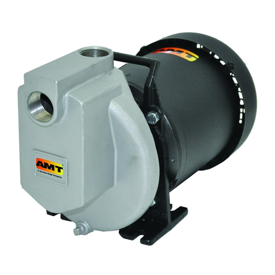
1-Inch Self-Priming Centrifugal Pumps
Refer to pump manual 1808-634-00 for General Operating and Safety Instructions.
DESCRIPTION
These stainless steel with Viton seal pumps are self-priming (to 6 ft. lift) units designed for transferring perchlorethylene and other non-flammable liquid chemicals.
Handle liquids from 40º F to 180º F (4º C to 82º C). Units should be used only with non-abrasive, non-flammable liquids that are compatible with pump component
materials.
MAINTENANCE
Make certain that power source is disconnected before attempting to
service or disassemble any components! If power disconnect is out-of-
sight, lock it in open position and tag it to prevent application of power.
INSTALLATION
When installing this pump in a "Permanent" fixed-bolted down location install
one each of the four rubbers washers under each slot in the motor adapter (Ref
#) foot. (Note: The washer come with the pump attached to the pump handle
with a cable). This will minimize vibration and provide a positive flat surface for
the pump foot.
MECHANICAL SEAL REPLACEMENT
Refer to Figures 1 and 2.
IMPORTANT: Always replace both seal seat and seal head to ensure proper
mating of mechanical seal components!
NOTE: It is not necessary to remove piping from pump casing. The motor and
impeller assembly are removed from back of casing.
1.
Drain pump before disassembling. Unscrew pipe plug (Ref. No. 13) to
drain most of liquid; some will be left in bottom.
2.
Unthread hex nuts (Ref. No. 4) and remove pump casing (Ref. No. 12)
and o-ring (Ref. No. 7) from casing cover (Ref. No. 6).
3.
To unscrew impeller (Ref. No. 11), turn counterclockwise (CCW) facing
impeller. Unscrew acorn nut (Ref. No. 16) and o-ring gasket (Ref. No. 15)
before unscrewing impeller.
Figure 1 - Mechanical Seal Replacement
4294-251-00
NOTE: A screwdriver slot or two flats for use with an open end 7/16" wrench are
provided at rear of motor shaft (remove bearing cap for access). To hold motor
shaft from turning, either insert a large screwdriver blade into the slot, or use a
7/16" wrench across the flats.
4.
Unthread cap screws (Ref. No. 5) and remove motor adapter (Ref. No. 3).
Seal head (Ref. No. 9) and impeller shims (Ref. No. 10) will come loose
at this time. NOTE: Casing cover will still be attached to motor adapter.
IMPORTANT: Retain impeller shims for use when reassembling unit.
5.
Push seal seat (Ref. No. 8) from casing cover with screwdriver.
6.
Clean adapter recess before inserting a new seal seat.
7.
Carefully wipe polished surface of new seal seat with a clean cloth.
8.
Wet outside of rubber portion of seal seat with a light coating of soapy
water.
9.
Press new seal seat squarely into cavity in casing cover. If seal seat does
not press squarely into cavity, it can be adjusted into place by pushing on
it carefully with a piece of pipe or dowel. Always use a piece of cardboard
between pipe and seal seat to avoid scratching seal seat. (This is a lapped
surface and must be handled very carefully).
10. After seal seat is in place, be sure that it is clean and has not been marred.
11. Using a clean cloth, wipe shaft and make certain that it is perfectly clean.
12. Carefully guide motor shaft through seal seat. Secure motor adapter on
motor mounting face.
13. Apply a light coating of soapy water to inside rubber portion of seal head
and slide onto shaft (with sealing face first) so that rubber portion is just
up over shaft shoulder.
Do not touch or wipe face of polished part of the seal head.
14. Replace any impeller shims which may have been removed in dis-
assembly (see "Shim Adjustment").
15. Screw impeller back in place, tightening until it is against shaft shoulder.
Replace o-ring gasket and acorn nut.
16. Remount o-ring and pump casing on casing cover.
IMPORTANT: Always inspect o-ring gasket for cracks or cuts when unit is
disassembled. Replace if damaged.
1
4294-98 thru 429N-98
9/2016
Advertisement
Table of Contents

Subscribe to Our Youtube Channel
Related Manuals for AMT 4294-98


Summary of Contents for AMT 4294-98
-
Page 1: Mechanical Seal Replacement
Instructions. Failure to comply with the safety instructions accompanying this product could result in personal injury and/or property damage! Retain instructions for future reference. AMT reserves the right to discontinue any model or change specifications at any time without incurring any obligation. - Page 2 4294-98 thru 429N-98 Specifications Information and Repair Parts Manual 1-Inch Self-Priming Centrifugal Pumps SHIM ADJUSTMENT When installing a replacement impeller (Ref. No. 11) or motor (Ref. No. 1), it may be necessary to adjust number of shims (Ref. No. 10) to ensure proper running clearance between impeller and casing.
- Page 3 4294-98 thru 429N-98 Specifications Information and Repair Parts Manual 1-Inch Self-Priming Centrifugal Pumps For Repair Parts contact dealer where pump was purchased. Please provide following information: -Model Number -Serial Number (if any) Part description and number as shown in parts list...
-
Page 4: Repair Parts List
4294-98 thru 429N-98 Specifications Information and Repair Parts Manual Repair Parts List Part Number for Models 4294-98 (1/3 HP) 4295-98 (1/2 HP) 4296-98 (3/4 HP) 4297-98 (1 HP) 4298-98 (1.5 HP) 429F-98 (1/2 HP) 429G-98 (3/4 HP) 429H-98 (1 HP) 429J-98 (1.5 HP) - Page 5 4294-98 thru 429N-98 Specifications Information and Repair Parts Manual NOTES: 4294-251-00 9/2016...
- Page 6 4294-98 thru 429N-98 Specifications Information and Repair Parts Manual NOTES: 4294-251-00 9/2016...
- Page 8 www.amtpump.com...
Need help?
Do you have a question about the 4294-98 and is the answer not in the manual?
Questions and answers