Baldor Series 10 Installation And Operating Manual

Baldor Series 10 Installation And Operating Manual

Inverter control
Table of Contents

Advertisement

AC INVERTER
Series 10
Inverter Control
Installation and Operating Manual
2/00
MN710

Advertisement

Table of Contents

Troubleshooting

loading

Summary of Contents for Baldor Series 10

  • Page 1 AC INVERTER Series 10 Inverter Control Installation and Operating Manual 2/00 MN710...
  • Page 2: Table Of Contents

    Table of Contents Section 1 General Information ......Limited Warranty ....... Safety Notice .
  • Page 3 Selection Of Operation Mode And Connection Diagrams 2-13 2 Wire Run/Stop Connections ....2-14 3 Wire Run/Stop Connections ....2-16 2 Wire Run/Stop, Electronic Potentiometer Connections .
  • Page 4 16-Load Torque ......17-Heatsink Temp ......21-Operating Mode .
  • Page 5 45-Decel Time #2 ......3-17 46-Decel Time Torque Limit ....3-17 47-DC Brake Time .
  • Page 6: General Information

    Claims for purchase price refunds, repairs, or replacements must be referred to BALDOR with all pertinent data as to the defect, the date purchased, the task performed by the control, and the problem encountered.
  • Page 7: Safety Notice

    Safety Notice This equipment contains voltages that may be as great as 800 volts! Electrical shock can cause serious or fatal injury. Only qualified personnel should attempt the start-up procedure or troubleshoot this equipment. This equipment may be connected to other machines that have rotating parts or parts that are driven by this equipment.
  • Page 8 WARNING: Be sure the system is properly grounded before applying power. Do not apply AC power before you ensure that all grounding instructions have been followed. Electrical shock can cause serious or fatal injury. WARNING: Do not remove cover for at least five (5) minutes after AC power is disconnected to allow capacitors to discharge.
  • Page 9: Specifications

    Specifications Horse Power 0.5 - 1 HP @ 115VAC, 1PH 0.5 - 5 HP @ 230VAC, 3PH 1 - 5 HP @ 460VAC, 3PH Input Voltage 95 - 127 VAC, 50/60Hz, Single Phase 187 - 253VAC, 50/60Hz, Three Phase 342 - 506VAC, 50/60Hz, Three Phase ±2% Phase Imbalance (3Phase Only)
  • Page 10: 31-Min Output Frequency

    Auto Restart Manual or Automatic Min. Output Frequency 0.1 to 400Hz Max. Output Frequency 20 to 400Hz Slip Compensation 0 to 12% Opto Input Impedance 4.5 k Ohms Ambient Temperature 0°C to 40°C (Maximum without derating) Humidity 90% Maximum RH non-condensing Altitude 3300 Ft.
  • Page 11: Watts Loss Data

    Operator Keypad Display Custom Backlit LCD Keypad 8 Key with Tactile Feel Functions Output Status Monitoring, Digital Speed Control, Parameter Setting and Display and Fault Log Display LED Indicators Red/Green for Status Analog Outputs Analog Outputs 1 Assignable Full Scale Range 0 to 10VDC Maximum Output Conditions 3 conditions plus calibration...
  • Page 12: Ratings

    Ratings Input Output Catalog No. (kW) Amps Volts Amps Amps Cont * Peak ID101F50-E (0.37) ID10101-E (0.75) ID102F50-E (0.37) ID10201-E (0.75) ID10202-E 11.3 (1.5) ID10203-E 10.4 10.6 15.9 (2.2) ID10205-E 17.6 16.7 25.1 (3.7) ID10401-E (0.75) ID10402-E (1.5) ID10403-E (2.2) ID10405-E 10.8 14.9...
  • Page 13 1-8 General Information...
  • Page 14: Installation

    Section 2 Installation This section describes the proper mounting and wiring of the BALDOR Series 10 Inverter. If problems arise, please refer to the troubleshooting information located in Section 4. Location and Mounting Select a mounting surface for the inverter that will allow the control to be mounted in a vertical position using the four mounting holes provided.
  • Page 15: Terminal Access Cover Removal

    Terminal Access Cover Removal To remove the Terminal Access Cover insert a small blade screwdriver into the slots located on the lower left and right hand corners of the access cover. Use a slight twisting motion while lifting upward to loosen one side. Use the same motion to loosen the other side then lift the cover off of the control.
  • Page 16: Terminal And Jumper Locations

    Terminal and Jumper Locations Figure 2-2 shows the location of the power terminal strip , control terminal strip , ground lug, and user adjustable jumper locations. Only motor and input power should be connected to the power terminal strip. Motor ground and input power earth ground should be connected to the ground lug.
  • Page 17 Caution: Separate over-current protection may be required by the National Electrical Code. The installer of this equipment is responsible for complying with the National Electrical Code and any applicable local codes which govern such practices as wiring protection, grounding, disconnects, and other current protection.
  • Page 18: Wire Size And Protection Devices

    Caution: Do not use power factor correction capacitors on the input power lines to the inverter or damage to the control may result. All external control wiring to the inverter should be run in a separate conduit from all other wiring. The use of shielded twisted pair wire is recommended for all control wiring.
  • Page 19: Recommended Terminal Tightening Torques

    Recommended Terminal Tightening Torques Tightening Torques Catalog No. Power Terminal TB1 Control Terminal Strip All Series 10 10 In-Lb (1.13 Nm) 2 In-Lb (0.23 Nm) Caution: Do not use this control with any input voltage other than stated on the control nameplate.
  • Page 20: Ac Power Connections

    AC Power Connections Connect the fused three phase AC power lines to the input power terminals L1, L2, and L3. The phase rotation of the input power is not important since the control is not sensitive to phase rotation of the input power. For single phase AC power connect to input power terminals L1 and L2.
  • Page 21: Motor Connections

    Motor Connections Connect the three phase power leads of the AC motor to terminals M1, M2, and M3 of the inverter power terminal strip. The motor ground lead or case ground should be connected to the inverter chassis ground screw. The motor should be connected to the inverter at all times during inverter operation.
  • Page 22 M-Contactor If required by local codes or for safety reasons, an M-Contactor (motor circuit contactor) may be installed. However, incorrect installation or failure of the M-Contactor or wiring may damage the control. Caution: If an M-Contactor is installed, the control must be disabled at least 20msec before the M-Contactor is opened.
  • Page 23: Logic Wiring

    Logic Wiring All logic and control connections are made at the control terminal strip located on the motor control board. Screw type terminals are provided for easy connection to your external control station and meters. The control terminal strip can be divided into four major categories as follows: 1) Analog command inputs.
  • Page 24: Analog Output

    Analog Output One programmable analog output is available for external monitoring of the drive condition. This output is available at terminals CM and MET. The output will be 0-10VDC. The positive lead of the external meter should be connected to terminal MET and the negative lead should be connected at terminal CM.
  • Page 25: Jumper J19 Input Selection

    motor to coast to a stop. The fault or coast to stop operation of the MOL input terminal is selected by parameter 77-External Trip Select. The selection of pull- up or pull-down logic is set by jumper J19. Jumper J19 Input Selection Jumper J19 is a pin-jumper selector located to the left and below the control terminal strip (See Figure 2-2).
  • Page 26: Relay Outputs

    115 VAC and 1 Amp maximum. Selection Of Operation Mode And Connection Diagrams Several operating modes are available within the Series 10 inverter. These operating modes define the basic operation of the input terminal configurations and motor control setup. The...
  • Page 27: Wire Run/Stop Connections

    2 Wire Run/Stop Connections Parameter 21 - Operating Mode = 2 or 3 Parameter 41 - Accel/Decel/Coast select = 0, 1, 2, 4, 5 or 6 Shield Forward Forward Shield Reverse Reverse Speed Select Speed Select Speed Select Speed Select Speed Select Speed Select Pull–Up Logic...
  • Page 28 2 Wire Run/Stop Connections Parameter 21 - Operating Mode = 2 or 3 Parameter 41 - Accel/Decel/Coast select = 3 or 7 Shield Forward Forward Shield Reverse Reverse Ramp Select Ramp Select Speed Select Speed Select Speed Select Speed Select Pull–Up Logic Pull–Down Logic See recommended tightening torques for terminal connectors.
  • Page 29: Wire Run/Stop Connections

    3 Wire Run/Stop Connections Parameter 21 - Operating Mode = 4 or 5 Shield Forward Forward Shield Reverse Reverse Stop Stop Speed Select Speed Select Speed Select Speed Select Pull–Up Logic Pull–Down Logic See recommended tightening torques for terminal connectors. Speed Select Function Open...
  • Page 30 2 Wire Run/Stop, Electronic Potentiometer Connections Parameter 21 - Operating Mode = 6 Shield Forward Shield Forward Reverse Reverse Preset Speed #4 Preset Speed #4 Increase Increase Decrease Decrease Pull–Up Logic Pull–Down Logic 3 Wire Run/Stop, Electronic Potentiometer Connections Parameter 21 - Operating Mode = 7 Shield Forward Forward...
  • Page 31: Mol Terminal Connections

    MOL Terminal Connections (77-External Trip Select) Shield Shield Shield Shield Normally Open Normally Closed Normally Open Normally Closed Device Device Device Device Pull–Up Logic Pull–Down Logic Relay Output Analog Meter Shield See recommended tightening torques for terminal connectors. 2-18 Installation...
  • Page 32 Jumper J19 - Used to select the active state of the opto isolated inputs (Pull-Up or Pull-down Logic) and to select the type of analog speed command signal to be applied. The available analog speed command signals are 0-5 VDC, 0-10 VDC, 0-20 mA, and 4-20 mA.
  • Page 33: Pre-Operation Checks

    Pre-Operation Checks Check of Electrical Items After completing all the installation steps and before applying line power to the system, carefully check the following items: Verify AC line voltage at source matches control rating. Inspect all power terminations for workmanship and tightness.
  • Page 34: Temporary Application Of Power

    Temporary Application of Power Double check electrical and mechanical connections before applying power to the control. Temporarily apply power and observe that the display is on. If this indication doesn’t occur, double check all connections and verify input voltage. If the display still is not on, refer to the troubleshooting table in Section 4.
  • Page 35 2-22 Installation...
  • Page 36: Operation

    Section 3 Operation 
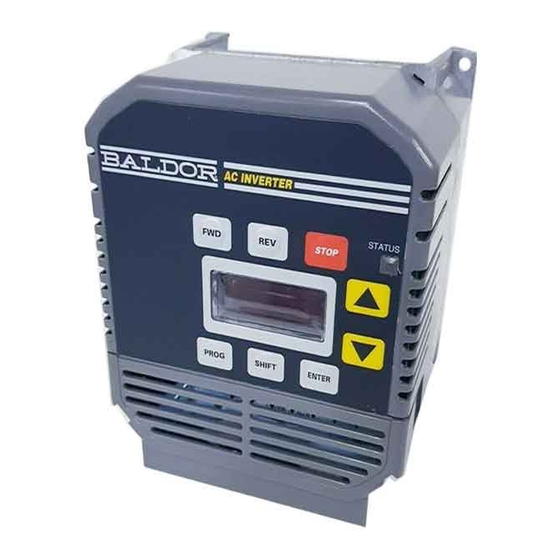
Keypad Key Functions The programming and basic operation of the Series 10 Inverter is accomplished by simple keystrokes on the operator control panel. The function of the keys are as follows: Operation 3-1...
  • Page 37 STOP Push to initiate a stop command. Depending on the setup of the control the motor will either ramp (Regen) or Coast to Stop. See 41-Accel/Decel/Coast Select in Section 3 for more information. FWD Used to initiate a forward direction run of the motor. REV Used to initiate a reverse direction run of the motor.
  • Page 38: Keypad Status Indicator

    Arrow is also used to decrement the set speed in the Stop Mode and decrement the actual speed in the Run Mode. The value will decrease at a faster rate after holding the DOWN Arrow key for 5 seconds. Pressing SHIFT while holding the DOWN Arrow will bypass the 5 second delay.
  • Page 39: Description Of Keypad Displays

    Description of Keypad Displays The custom, back-lit, LCD display provides information on drive operation and programming. The four large 7-segment displays show inverter output and programming data. Two smaller 7-segment displays are used to indicate parameter numbers. Special symbols and displays provide further clarification of drive operation.
  • Page 40: Stop Mode

    Symbol Description Forward direction commanded Reverse direction commanded Program Mode Selected (Steady) Parameter Value may be changed (Blinking) Drive is Stopped or running frequency being set Overvoltage condition Undervoltage condition Running in Torque Limit Running in Overcurrent condition (Blinking) Overcurrent Fault (Steady) TEMP Running in Overtemperature condition (Blinking) Overtemperature Fault (Steady)
  • Page 41: Program Mode

    Program Mode Use the Program Mode to customize the control to suit a variety of applications by programming the operating parameters. From the Stop Mode press the PROG key to access the Level 1 Program Mode. Hold the SHIFT key and press the PROG key to access the Level 2 Program Mode.
  • Page 42: Level One Parameter Adjustments

    Level One Parameter Adjustments 07-Last Fault - A view only parameter that displays the most recent fault condition along with the elapsed time from the last restart of the control and the fault occurrence. The elapsed time is indicated in 0.1 hour increments with 0.9 hour maximum displayed.
  • Page 43: Operating Mode

    21-Operating Mode - Sets the basic operation of the inverter input terminals and keypad FWD and REV keys. The Series 10 inverter has several modes of operation to fit various application requirements. Please refer to the following table to determine which operating mode is right for your application.
  • Page 44 Electronic Pot Control Terminal Logic Parameter 21-Operating Mode = 6 or 7 COMMAND CONTROL TERMINALS DESCRIPTION STOP OPEN OPEN Speed = 0 CLOSED CLOSED FWD Decrease CLOSED OPEN CLOSED FWD Hold CLOSED OPEN OPEN OPEN FWD Increase CLOSED OPEN OPEN CLOSED REV Decrease OPEN...
  • Page 45: Torque Boost

    Note: Since the motor uses rotor slip to produce motor torque, the motor speed will not necessarily increase/decrease linearly with a linear increase/decrease in applied motor frequency. Some trial and error may be necessary to find the optimum Accel and Decel settings for your application. If the control trips (faults) during rapid accel or decel, selecting longer ramp times will help eliminate the trips.
  • Page 46: 03-Rated Current

    67-Timed Overload Trip - Sets the amount of overload that will cause a Timed Overload fault (F20) to occur. A Timed Overload fault will occur when the output current reaches 150% of the set value for 1 minute. The Timed Overload Trip is active between 30-100% of the Inverter Rated Current (03-Rated Current) parameter value.
  • Page 47 71-Analog Output Select - Allows setting of the analog output available at the control terminal MET to represent various drive operating conditions. The analog output is 0 to 10 VDC nominal. The analog output is useful in applications where a higher level control is monitoring the operation of the control to make process decisions based on the current status of the inverter.
  • Page 48: 08-Second Fault

    Parameter 75-RELAY OUTPUT SELECT Value Description Ready. Inactive at Fault, Low Voltage, Idle, and in Program Mode Fault Forward and Reverse Output, Output Frequency above 0.5 Hz Reverse Output, Output Frequency above 0.5 Hz Forward Output, Output Frequency above 0.5 Hz Output Frequency less than 0.5 Hz Output at Set Frequency Output Frequency greater than Parameter 36-Preset Speed #4...
  • Page 49: 24-Analog Command Select

    occurrence. The elapsed time is indicated in 0.1 hour increments with 0.9 hour maximum displayed. The two left most digits displayed is the fault code and the right most digits is the elapsed time. 24-Analog Command Select - Selects the type of external speed reference command the control should be expecting to see in your application.
  • Page 50: 35-Preset Speed #3

    35-Preset Speed #3 - Sets the output frequency when Preset Speed #3 is commanded at the Control Terminal Strip. The adjustable range is 0.1-400 Hz. The factory setting is 40 Hz. 36-Preset Speed #4 - Sets the output frequency when Preset Speed #4 is commanded at the Control Terminal Strip.
  • Page 51: Accel/Decel/Coast Select

    41-Accel/Decel/Coast Select - Sets when Accel Times 1 or 2 and Decel Times 1 or 2 are called upon to affect the output frequency of the inverter. Also can select a Coast to Stop deceleration after a Stop command. The factory setting is “0” indicating that parameters 42-Accel Time #1 and 43-Decel Time #1 are active.
  • Page 52: 44-Accel Time #2

    44-Accel Time #2 - Sets the time in seconds for the output frequency of the inverter to linearly increase from 0 Hz to the frequency specified by parameter 32-Max Output Frequency. The adjustable range is from 0.1 Sec to 600 Sec. 45-Decel Time #2 - Sets the time in seconds for the output frequency of the inverter to linearly decrease from the frequency specified by parameter 32-Max Output Frequency to 0 Hz.
  • Page 53: 48-Dc Brake Voltage

    Parameter 41-Parameter 47-DC BRAKE TIME Value Braking Action / Function DC Braking Disabled Timed DC Braking (Parameter Value Sets Braking Time) When both FWD and REV Terminals are closed (active) and Parameter 21-OPERATING MODE = 2, 3, 4, 5, 6, or (Terminal Strip Start/Stop Control) 0.05 0.05...
  • Page 54: 51-V/Hz Profile

    51-V/HZ Profile - Sets the output V/Hz ratio for all values of output voltage verses output frequency up to the Control Base Frequency point. This adjustment will define how much voltage is applied to the motor in various segments of the output frequency range.
  • Page 55: 53-Control Base Frequency

    53-Control Base Frequency - Sets the point on the V/Hz profile where the output voltage becomes a constant value with increasing output frequency. The base frequency point defines the output frequency where the motor goes from constant torque (or variable torque) to constant horsepower operation. The range of adjustment is from 26 to 960 HZ.
  • Page 56: 62-Load Torque Limit Rev

    62-Load Torque Limit REV - Sets the maximum amount of current that is supplied to the motor under a motoring reverse condition before Torque Limiting takes affect. The range of adjustment is 30- 150% of parameter 03-Rated Current. The factory setting is 150%. 63-Regen Torque Limit FWD - Sets the maximum amount of current that is absorbed by the control from the motor under a regenerative forward condition before Torque Limiting takes...
  • Page 57: 77-External Trip Select

    77-External Trip Select - Sets if the control will trip (Fault F07) or Coast to Stop if the condition at control terminal MOL is changed. If set to 0 or 1, then the control will automatically shut down indicating an External Trip (F07). If set to 2 or 3 the output to the motor is turned off and the motor is allowed to coast (free wheel) to a stop.
  • Page 58: 81-Factory Settings

    Auto Restart - In the event of a power failure or inverter fault, the Series 10 inverter can be adjusted to restart automatically. The number of restart attempts after a fault condition can be set by specifying the allowable number of trips within a ten minute time period.
  • Page 59 If the inverter is set in an Auto Restart Mode and normal operation is using input power to start and stop the motor, the inverter may be started once every two minutes. The inverter will prevent operation if more frequent starts are commanded using line power connection.
  • Page 60: 84-Display Options

    Parameter 82-Start Options - Continued Value Description Manual Restart. If parameter 21-OPERATING MODE = 2, 3, or 6 (2-Wire Control) Then Run FWD or REV commands must be removed and then re-applied to start after application of line power. Auto Restart is active after application of line power and Run Command is given at the Control Terminal Strip.
  • Page 61: 87-Security Access Code

    Access Code will not be displayed. The factory setting is Note: Please write down your chosen Security Access Code in a secure location. If you cannot gain entry into the security area to change a parameter, please contact BALDOR. 3-26 Operation...
  • Page 62: Troubleshooting

    Section 4 Troubleshooting Diagnostic Displays Several diagnostic displays are available from the keypad display to aid in trouble shooting the inverter. These displays may occur from normal operation or from a fault trip condition. Manual Restart (Line Start Lockout). See parameter 82–START OPTIONS for more information.
  • Page 63 In the event of a fault trip, the display will show the fault code and the STATUS indicator will begin to blink red. Pressing the UP Arrow before the fault is reset will display the status of the drive at the time of the fault. More than one display symbol may be shown to better define the cause of the fault.
  • Page 64: Maintenance

    Maintenance The BALDOR Series 10 inverters require very little maintenance, if any, and should provide years of trouble free operation when installed and applied correctly. Occasional visual inspection should be considered to insure tight wiring connections and to avoid the build up of any dust, dirt, or foreign debris. The control...
  • Page 65 Indication Possible Cause Corrective Action MIN. Output Frequency Adjust setting of Min. Output Limit set too high Frequency Limit Improper speed command Verify control is receiving proper command signals at the control Motor will terminal strip not stop not stop rotation Verify control is set to receive your type of speed command...
  • Page 66 Indication Possible Cause Corrective Action Correct the input power problem Use step down transformer Input voltage too high Input voltage too high overvoltage overvoltage Use line reactor to minimize spikes fault Decel rate set too quickly Adjust Decel rate setting Overhauling motor load Correct the motor load problem Correct the input power problem...
  • Page 67 4-6 Troubleshooting...
  • Page 68: Illustrations

    Section 5 Illustrations Illustrations 5-1...
  • Page 69 5-2 Illustrations...
  • Page 70 3 & 5 HP NEMA 1 230 & 460VAC Illustrations 5-3...
  • Page 71 5-4 Illustrations...
  • Page 72: Appendix A Parameters

    Appendix A Parameters Parameter List Param Parameter Description Adj. Factory User Range Setting Setting Software revision View only View only Rated current View only View only Last fault View only View only Second fault View only View only First fault View only View only Output frequency...
  • Page 73 Parameter List – Continued Param Parameter Description Adj. Factory User Range Setting Setting DC brake time 0-5sec 0.2sec DC brake voltage 0-15% Factory V/Hz profile Torque boost 0-25% Factory Control base frequency 26-960Hz 60Hz Maximum output volts 185- Factory 480Volts Load torque limit FWD 30-150% 150%...
  • Page 74 BALDOR ELECTRIC COMPANY P.O. Box 2400 Fort Smith, AR 72901- -2400 (501) 646- -4711 Fax (501) 648- -5792 Form 1099A © Baldor Electric Company Printed in USA MN710 2/00...

Table of Contents