Table of Contents
Advertisement
Quick Links
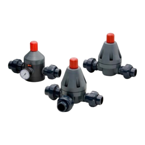
Self Control Valves
Pressure Reducing Type (V182,V82)
Pressure Relief Type
Pressure Retaining Type (V186)
User's Manual
【H-V063-E-9】 Self Control Valves (Pressure Reducing Type / Pressure Relief Type / Pressure Retaining Type)
(V185)
Installation, Operation and Maintenance Manual
Serial No.
Contents
H-V063-E-9
1
2
2
3
5
6
7
7
8
9
10
11
12
13
14
15
16
16
Advertisement
Table of Contents

Related Manuals for AsahiAV V82


Summary of Contents for AsahiAV V82
-
Page 1: Table Of Contents
Installation, Operation and Maintenance Manual Serial No. H-V063-E-9 Self Control Valves Pressure Reducing Type (V182,V82) Contents (V185) Pressure Relief Type Pressure Retaining Type (V186) 1. Be sure to read the following warranty clauses of our product 2. General operating instructions 3. -
Page 2: Be Sure To Read The Following Warranty Clauses Of Our Product
Installation, Operation and Maintenance Manual This user’s guide contains very important information for the proper installation, maintenance and safe use of an ASAHI AV Product. Please store this manual in an easily accessible location. <Warning & Caution Signs> This symbol reminds the user to take caution due to the potential for serious injury or death. Warning This symbol reminds the user to take caution due to the potential for damage to the valve if used in such a manner. -
Page 3: General Operating Instructions
Installation, Operation and Maintenance Manual 2. General operating instructions - Using a positive-pressure gas with our plastic piping may pose a dangerous condition due to the Warning repellent force particular to compressible fluids even when the gas is under similar pressures used for liquids. -
Page 4: Name Of Parts
Installation, Operation and Maintenance Manual 4. Name of parts ○ Pressure Reducing Type V182 (15mm~40mm { ½”- 1½” }) V82 (50mm {2”};PTFE spec only) Description Description Description Description [a1] Body (Bottom) [g] Compressor [n1] O-Ring (A) [4] Union nut [a2]... - Page 5 Installation, Operation and Maintenance Manual ○Pressure Relief Type V185 (15mm~50mm { ½”-2” }) Description Description Description Description [a] Body [g] Compressor [l] [4] Union nut [b] Housing [h] Compression spring [o] Bolt, Nut, Washer [5] O-Ring (C) [c] Diaphragm [i] Lock nut [2]...
-
Page 6: Product Functions And Specifications
5. Product functions and specifications Functions - The pressure reducing type (V182/V82) maintains a constant working pressure regardless of changes or fluctuations in inlet pressure. Upon changes in pressure, the diaphragm either lifts against the internal spring or is pressed down by the spring force until a state of equilibrium is re-established. -
Page 7: Working Pressure Vs. Temperature
Installation, Operation and Maintenance Manual 6. Working pressure vs. temperature - Pressure Reducing Type (V182, V82), Pressure Relief Type (V185), Pressure Retaining Type (V186) 【H-V063-E-9】 Self Control Valves (Pressure Reducing Type / Pressure Relief Type / Pressure Retaining Type) -
Page 8: Valve Flow Characteristic
Installation, Operation and Maintenance Manual 7. Valve flow characteristic - Pressure Reducing Type (V182) - Pressure Reducing Type (V82) - The friction coefficient increases with the flow rate and the outlet pressure decreases. : Set pressure (at a flow rate of 0 L/h) :... -
Page 9: Pressure Relief & Retaining Type
Installation, Operation and Maintenance Manual - Pressure Relief Type (V185), Pressure Retaining Type (V186) - The friction coefficient and inlet pressure increase with the flow rate. : Set pressure (at a flow rate of 0 L/h) E : Working pressure A... -
Page 10: Installation Procedure
Installation, Operation and Maintenance Manual 8. Installation procedure - When suspending and supporting a valve, take care and do not stand under a suspended valve. Warning - Be sure to conduct a safety check on all hand and power tools to be used before beginning work. -
Page 11: Flanged End
Installation, Operation and Maintenance Manual Flanged End - Use flat faced flanges for connection to AV Valves. Caution - Ensure that the mating flanges are of the same standards. - Be sure to use sealing gaskets (AV Gasket), bolts, nuts, and washers and tighten them to specified torques. -
Page 12: Threaded End
Installation, Operation and Maintenance Manual Threaded end - Avoid excessive tightening. (The valve can be damaged.) Caution - The union nut of this product is fastened lightly so that it can be loosened easily. Be sure to remove the end connector before carrying out the work. (Failure to so may cause external leakage.) - Make sure that the threaded connections are plastic x plastic. -
Page 13: Socket End
Installation, Operation and Maintenance Manual Socket end - When using an adhesive, ventilate the space sufficiently, prohibit the use of a fire in the vicinity, Warning and do not inhale adhesive vapors directly. - If an adhesive gets into contact with your skin, wash it off immediately. If you feel sick or find anomaly, receive a physician's diagnosis and take appropriate measures promptly. -
Page 14: Adjustment Procedure For Working Pressure
Installation, Operation and Maintenance Manual 9. Adjustment procedure for working pressure - Tighten the lock nut securely. (Too weak a tightening torque on a lock nut may cause it to Caution loosen.) - When the adjusting screw keeps being turned counterclockwise, it comes off. Therefore, handle it within a range that it will not come off. -
Page 15: Disassembling Method For Replacing Parts
Installation, Operation and Maintenance Manual 10. Disassembling method for replacing parts - When replacing valves and parts, completely eliminate pressure in the pipe. Warning - When conducting piping work, wear personal protective equipment Caution appropriate to the contents of work. (Failure to do so may cause an injury.) - When disassembling the valve, unlock the adjustment screw until the compression spring is discharged. -
Page 16: Inspection Items
Installation, Operation and Maintenance Manual Pressure Reducing Type (V82) Disassembly Procedure 1) Remove the cap [l] from the top of the housing [b]. 2) Loosen the lock nut [i] counterclockwise with a spanner wrench and the adjusting screw [j] counterclockwise with an Allen wrench. -
Page 17: Troubleshooting
Installation, Operation and Maintenance Manual 12. Troubleshooting Problem Cause Treatment The bolt [o] has loosened. Tighten up the bolt. Fluid leaks from the body and the The diaphragm and/or O-ring (A, B) have Replace the diaphragm housing. failed. and/or O-ring. The union nut is loosened. - Page 18 Installation, Operation and Maintenance Manual Self Control Valves Pressure Reducing Type / Pressure Relief Type / Pressure Retaining Type 15-50mm (½”-2”) Distributor http://www.asahi-yukizai.co.jp/en/ Information in this manual is subject to change without notice. April 2018 【H-V063-E-9】 Self Control Valves (Pressure Reducing Type / Pressure Relief Type / Pressure Retaining Type)
Need help?
Do you have a question about the V82 and is the answer not in the manual?
Questions and answers