Table of Contents
Advertisement
Quick Links
Serial No.: H-A079-E-00
Butterfly valve type 58
Pneumatic Actuated
Type FL
700mm (28") ~900mm (36")
User's
Manual
Thank you very much for choosing our product.
This instruction manual is for your safety to use our product.
This manual contains important information. Be sure to read this manual before handling the product.
After reading this manual, the user can refer to it at any time.
Please be sure to keep it.
[User's Manual] Butterfly valve Type 58 Pneumatic Actuated Type FL 700mm (28") ~900mm (36")
- 1 -
Advertisement
Table of Contents

Related Manuals for AsahiAV 58 FL


Summary of Contents for AsahiAV 58 FL
- Page 1 Serial No.: H-A079-E-00 Butterfly valve type 58 Pneumatic Actuated Type FL 700mm (28”) ~900mm (36”) User’s Manual Thank you very much for choosing our product. This instruction manual is for your safety to use our product. This manual contains important information. Be sure to read this manual before handling the product. After reading this manual, the user can refer to it at any time.
- Page 2 Serial No.: H-A079-E-00 -SAFETY PRECAUTIONS- This instruction manual is written on the assumption that the person who handles our products has a basic knowledge of our products, electrical equipment, machinery, control, etc., and it contains technical terms depending on the handling contents. Please read this manual carefully and fully understand the contents and observe the safety precautions for proper use.
-
Page 3: Table Of Contents
Serial No.: H-A079-E-00 Table of contents 1. Our product warranty coverage ··························································································· 4 Applicable to ..................................4 Warranty Period ..................................4 Guaranteed range ................................. 4 Disclaimer ....................................4 2. Safety Instructions ················································································································ 5 Unpacking, Transportation and Storage .......................... 5 Product Handling .................................. 6 3. -
Page 4: Our Product Warranty Coverage
Serial No.: H-A079-E-00 1. Our product warranty coverage Unless otherwise stated in the Contract or Specifications, etc., the warranty for the piping material products (hereinafter referred to as "applicable products") such as valves manufactured or sold by us is as follows. Applicable to This warranty applies only when the product is used in Japan. -
Page 5: Safety Instructions
Serial No.: H-A079-E-00 2. Safety Instructions Unpacking, Transportation and Storage WARNING Serious injury can result. Prohibition ▶ When hanging or slinging a valve, pay sufficient attention to safety, and do not enter under the load. CAUTION The valve can be damaged, damaged, or leak. Prohibition ▶... -
Page 6: Product Handling
Serial No.: H-A079-E-00 Product Handling WARNING Serious injury can result. Prohibition ▶ Do not disassemble the actuator. ▶ Do not touch moving parts during operation with hands, feet or tools. There is a danger of injury. Forcing ▶ If positive pressure gas is used for our resin piping material, a dangerous condition may occur due to the repulsive force peculiar to compressible fluids even if the pressure is the same as the water pressure. - Page 7 Serial No.: H-A079-E-00 Handling of products (continued) WARNING Doing so may cause the actuator to stop moving. Forcing ▶ Prevent foreign matter, water droplets, oil, etc. from entering the actuator through the air piping or air intake or exhaust holes. Be especially careful in areas where there is a possibility of snow accumulation, as snow melting water may enter.
-
Page 8: Name Of Each Part
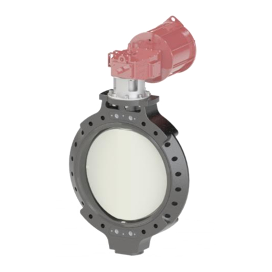
Serial No.: H-A079-E-00 3. Name of each part Body [35] Actuator [30] Stand Disc Seat [38] Joint 4. Product Specifications Product model code list Butterfly valve type 58 Pneumatic Actuated type FL CODE * *** | | | | | |... -
Page 9: Relationship Between Maximum Allowable Pressure And Temperature
Serial No.: H-A079-E-00 Relationship between maximum allowable pressure and temperature : 700 mm (28") : 800 mm (32"), 900 mm (36") {150} {150} {70} {70} {-40} {-5} {30} {70} {105} {140} {175} {210} {250} {-40} {-5} {30} {70} {105} {140} {175} {210} {250} TEMP. -
Page 10: Solenoid Valve Specification
Serial No.: H-A079-E-00 Solenoid Valve Specification Applicable Operation nominal diameter Model code Air pipe bores Power consumption mm(inch) 700~900 AC:1.55VA Double action VF5120-□D1-03N NPT3/8 (28”~36”) DC:1.5W VF5120-□D1-03N Text entry Degree of protection AC100V AC200V AC110V AC220V DC24V DC12V DC240V ※The photo is an image AC24V JIS symbol Terminal Diagram... -
Page 11: Filter Regulator Specifications
Serial No.: H-A079-E-00 Filter regulator specifications Applicable nominal Operation diameter Model code Air pipe bores Element filtration rate mm(inch) Double action 700~900(28”~36”) AW30-N03G-R-A NPT3/8 5 μm JIS symbol ※The photo is an image Speed controller specifications Applicable nominal diameter Operation Air pipe bores Model code mm(inch)... -
Page 12: Limit Switch Box Specifications
Serial No.: H-A079-E-00 Limit switch box specifications Applicable nominal Switch Protection Rated voltage Resistance Operation Model code diameter contact grade load (A) mm(inch) AC250 AC125 Double 700~900 YT-850M3 Silver contact IP67(IEC529) DC250 action (28”~36”) DC125 DC30 ※The photo is an image Internal circuit [User’s Manual] Butterfly valve Type 58 Pneumatic Actuated Type FL 700mm (28”) ~900mm (36”) - 12 -... -
Page 13: Piping Method
Serial No.: H-A079-E-00 5. Piping method Wafer shape WARNING Serious injury can result. Prohibition ▶ When hanging or slinging the valve, pay careful attention to safety and do not enter the area under the load. ▶ Do not use the eye plate of the actuator when lifting the valve. Forcing The valve may fall and cause injury. - Page 14 Serial No.: H-A079-E-00 CAUTION The valve may be damaged. Prohibition ▶ Do not over-tighten when piping support is removed with a U-band, etc. ▶ When installing piping, do not install it in the fully closed state. (The disc may get caught in the seat and the operating torque may become heavy, making it impossible to open and close it.) ▶...
- Page 15 Serial No.: H-A079-E-00 CAUTION ▶ The product is in the "Good" state as shown in Fig. 5-1. Before opening or closing the valve for piping installation, be sure to return the disc to the original condition (Refer to Forcing "Good" in Fig. 5-1) after operation. ▶...
- Page 16 Serial No.: H-A079-E-00 ▶ Torque wrench ▶ Spanner wrench ▶ Through-bolt ▶ Screw-in bolt ▶ Nut, Washer Necessary items ▶ Short pipe ▶ waste cloth Dimensions of Through Bolt and Screw-in Bolt ・The length of the bolt to be used varies depending on the connection standard and flange material. Obtain the bolt length using the following formula.
- Page 17 Serial No.: H-A079-E-00 [Procedure] Between valve faces 1) Set the short tube in advance. Center and short + 150mm(6”) or more tube of the valve when the valve was raised Valve bottom dimensions Short pipe Place the short tube on the pedestal so that the About + 50mm(2”)...
-
Page 18: Product Support
Serial No.: H-A079-E-00 Product support WARNING The valve may be damaged or broken. Prohibition ▶ Do not cause large vibrations to the valve by the piping around the pump. Damage to the valve body and piping may occur. Forcing ▶ Install a valve support. Necessary ▶... -
Page 19: Air Piping Method
Serial No.: H-A079-E-00 6. Air piping method WARNING Otherwise, the actuator may be damaged or malfunction may result. Prohibition ▶ Do not remove the protective plug until just before connecting the air piping. ▶ Do not overtighten the fitting for air piping. Otherwise, the actuator may be damaged or malfunction may result. - Page 20 Serial No.: H-A079-E-00 Necessary ▶ Metal or tube for air piping ▶ Fittings for metal pipes or tubes ▶ Spanner wrench ▶ Sealing tape items [Procedure] 1) Wrap sealing tape around the male thread of the fitting, leaving approximately 3mm away from the end. 2) Tighten a fitting to the air piping port of the actuator or pneumatic equipment (speed controller, filter regulator, solenoid valve).
-
Page 21: How To Connect Options
Serial No.: H-A079-E-00 7. How to Connect Options Limit switch WARNING Electric shock or sudden start of the machine. Prohibition ▶ Do not connect or disconnect wires to the limit switch while the power is on. ▶ Do not connect wires in an environment where rainwater or moisture may be splashed on the wires (e.g. -
Page 22: Solenoid Valve
Serial No.: H-A079-E-00 Solenoid valve WARNING There is a risk of electric shock. Prohibition ▶ Do not connect wires or disconnect wires to the solenoid valve in an energized state. ▶ Do not connect wires in an environment where rainwater or moisture may be splashed on the wires (e.g. -
Page 23: Manual Operation
Serial No.: H-A079-E-00 8. Manual operation WARNING There is a danger of injury. Prohibition ▶ Do not supply air during manual operation. There is a danger of injury. Forcing ▶ Do not supply air to the actuator. ▶ Exhaust the inside of the actuator to remove residual pressure. ▶... - Page 24 Serial No.: H-A079-E-00 Intermediate Open Closed Bypass valve (open) Pipe Directional control valve Pipes, etc. Top surface: 250mm Upper oil level height: 170mm Minimum oil level height: 70mm [User’s Manual] Butterfly valve Type 58 Pneumatic Actuated Type FL 700mm (28”) ~900mm (36”) - 24 -...
-
Page 25: Air Operation
Serial No.: H-A079-E-00 9. Air Operation CAUTION Doing so may damage the actuator. Forcing ▶ Always use the product within the range of the indicated product specifications. [Procedure] 1) Supplies air to the air piping port. 2) Check that the air supply side and the display position match. ※The position of the pointer when fully closed may not reach the position shown in the figure slightly due to the tightening allowance of the disc. -
Page 26: How To Adjust The Stopper
Serial No.: H-A079-E-00 10. How to adjust the stopper WARNING There is a danger of injury. Prohibition ▶ Do not supply air during adjustment. Doing so may cause the actuator to malfunction. Forcing ▶ Be sure to fix the stopper with the lock nut after adjustment. (Do not use excessive force to tighten.) Necessary ▶... -
Page 27: How To Adjust Open/Close Speed
Serial No.: H-A079-E-00 11. How to adjust open/close speed Necessary ▶ Spanner wrench items [Procedure] 1) While holding the speed controller adjustment knob with your finger, rotate the lock nut counterclockwise to release the adjustment knob. 2) Turn the adjustment knob clockwise until it does not turn. * Do not turn it too hard. -
Page 28: Inspection Item
Serial No.: H-A079-E-00 12. Inspection item CAUTION Leakage may occur due to changes in temperature or aging during long-term storage, Forcing resting, or use. ▶ Please enforce daily inspection and periodic inspection. Daily inspection Inspection items Guideline of Check point Treatment method and method judgment... -
Page 29: Periodic Inspection
Serial No.: H-A079-E-00 Periodic inspection * Guideline for the inspection cycle: 3 months Inspection items Guideline of judgment Check point Remedy for malfunctions and method Vibration To differences from Valves and actuators Recheck the operating conditions (palpation) other parts No and remove the source of vibration Remove the valve from the pipe and replace the valve or actuator... - Page 30 Serial No.: H-A079-E-00 Periodic inspection * Guideline of the inspection cycle: 6 months Inspection items and Guideline of Check point Remedy for malfunctions method judgment On the manual handle Smoothly Manual Remove the valve from the pipe and Operability (touch) Turning replace the valve or actuator operation unit...
-
Page 31: Troubleshooting
Serial No.: H-A079-E-00 13. Troubleshooting Problem Cause Treatment The hand pump does not move The valve is already fully open (or Rotate the handle in the opposite during manual operation. fully closed) direction Air is supplied to the actuator. Or Stop air supply and release internal residual pressure remains pressure... - Page 32 Serial No.: H-A079-E-00 Troubleshooting (continued) Problem Cause Treatment Do not open or close by air Piping stress is applied to the Remove the piping stress operation. valve The torque of the valve has Reconfirm the conditions of use increased due to the effects of the fluid (temperature, components, pressure, etc.) Interference between the disc and...
- Page 33 Serial No.: H-A079-E-00 Troubleshooting (continued) Problem Cause Treatment Fluid leaks from valve O-ring is scratched, worn, melted, Stop using the product immediately, (external leak) or altered remove the valve from the piping, and replace the valve Scratches or wear are found on Stop using the product immediately, the sliding or fixing surfaces of the remove the valve from the piping, and...
-
Page 34: How To Inquire About Defects Or Replacement
Serial No.: H-A079-E-00 14. How to inquire about defects or replacement WARNING When burnt, toxic gas is generated. Forcing ▶ When disposing of the product or parts, please dispose of them according to the guidelines of each local authority by a professional disposal company. [User’s Manual] Butterfly valve Type 58 Pneumatic Actuated Type FL 700mm (28”) ~900mm (36”) - 34 -... - Page 35 Serial No.: H-A079-E-00 [User’s Manual] Butterfly Valve 58 Pneumatic Actuated Type FL 700mm (28”)~900mm (36”) https://www.asahi-yukizai.co.jp/en Information in this manual is subject to change without notice. April 2023 [User’s Manual] Butterfly valve Type 58 Pneumatic Actuated Type FL 700mm (28”) ~900mm (36”) - 35 -...
Need help?
Do you have a question about the 58 FL and is the answer not in the manual?
Questions and answers