Table of Contents
Advertisement
Advertisement
Table of Contents

Related Manuals for Teledyne Cetac Technologies ASX-560


Summary of Contents for Teledyne Cetac Technologies ASX-560
- Page 1 ASX-560 / ASX-280 Autosampler Operator’s Manual Manual Part Number 480215 Rev2...
- Page 2 Microsoft Corporation in the United States and other countries. 480215 Rev2, September, 2015 PharMed and Tygon are registered Teledyne CETAC Technologies authorizes its trademarks of Saint-Gobain Performance customers to reproduce, transmit, or store Plastics. this document in its entirety, including this page, for the express purpose of installing, DuPont™, Kapton®, Teflon®, Tefzel®...
-
Page 3: Table Of Contents
Contents Overview............................ 7 Introduction ......................7 About This Manual ........................ 7 Autosampler Standard Components ................8 Who Should Read This Book..................7 Additional Equipment Required ...................10 Optional Accessories ......................11 Chemical Compatibility .....................12 Where to Go for More Information................13 Choosing a Location......................15 Preparing for Installation ................. - Page 4 ASX-560 / ASX-280 Autosampler Operator’s Manual Contents Connecting the Autosampler to the Host Computer..........43 Connecting a Serial Cable....................43 Connecting a USB Cable....................44 Basic Verification.........................47 Verifying Installation (IQ and OQ)..............47 Installation Qualification (IQ)..................48 Inventory of Supplied Equipment................48 Operating Environment Checklist................. 48 Visual Inspection......................
- Page 5 ASX-560 / ASX-280 Autosampler Operator’s Manual Contents Replacing the Rinse Station.....................80 Installing the New Z-Drive ..................76 Replacing the Sample Tray ....................81 Replacing the Home Flag/Guide Plate................81 Power System Problems....................83 Troubleshooting the Autosampler ..............83 Communications Interface Problems .................84 RS-232 Serial Cable Problems.................84 USB Cable Problems....................84...
- Page 6 ASX-560 / ASX-280 Autosampler Operator’s Manual Contents This page is intentionally blank.
-
Page 7: Overview
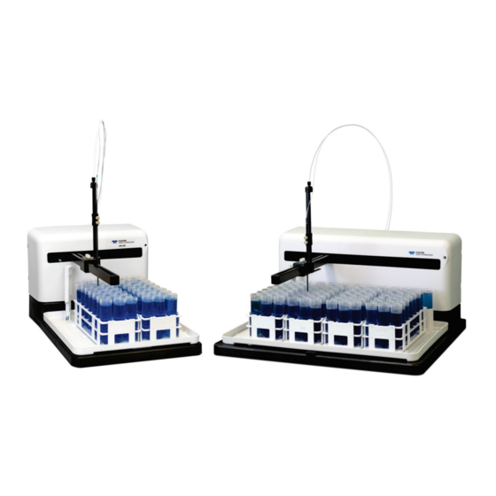
The CETAC ASX-560 and ASX-280 autosamplers are designed to be sturdy, reliable, and easy to use. It provides automated sample introduction that enables you to perform other tasks while the autosampler runs. The ASX-560 autosampler automatically introduces up to 360 samples when fully loaded;... -
Page 8: Autosampler Standard Components
Sample Tray. The sample tray holds the rinse station, sample racks, and standards vials in place. The tray also contains small spills. Sample Vial Racks. The ASX-560 includes four sample vial racks; the ASX- 280 includes two racks. You can choose from different rack sizes (common sizes fit 21, 24, 40, 60 or 90 vials per rack). - Page 9 ASX-560 / ASX-280 Autosampler Operator’s Manual Chapter 1: Introduction used to connect the rinse station to the rinse source and the waste container. Arm. The arm moves the sample probe horizontally. Z-Drive. The Z-drive moves the sample probe vertically. The Z-drive assembly includes a Y-axis slider block and guide plate as well as the sample probe.
-
Page 10: Additional Equipment Required
ASX-560 / ASX-280 Autosampler Operator’s Manual Chapter 1: Introduction CD. The CD contains, if applicable: Utility software USB device drivers Manuals Other application-specific information Supplied components depend on the application and the exact version of the ... -
Page 11: Optional Accessories
Optional Accessories You may need optional accessories in addition to the standard components included with the autosampler. See the ASX-560 / ASX-280 Autosampler Spare Parts and Accessories Catalog for details. Available accessories include: Sample Probes. Extra probes are available in a variety of diameters. See ... -
Page 12: Chemical Compatibility
ASX-560 / ASX-280 Autosampler Operator’s Manual Chapter 1: Introduction Chemical Compatibility The autosampler operates reliably under a wide variety of conditions. No metallic components are exposed above the sample vials. The top cover and base are made from polypropylene. The arm and Z-drive are made from carbon fiber. -
Page 13: Where To Go For More Information
Web site: www.cetac.com available on the CETAC Web site. ASX-560 / ASX-280 Autosampler Spare Parts and Accessories Catalog, CETAC Autosampler Safety Guide provides basic safety-related information in a variety of languages. Online help within the ASX Dashboard software. - Page 14 ASX-560 / ASX-280 Autosampler Operator’s Manual Chapter 1: Introduction This page is intentionally blank.
-
Page 15: Choosing A Location
28 cm (14") 62 cm (24.4") without Z-Drive with Z-drive and tubing Width 58 cm (232.5) Depth 55 cm (21.6") 59 cm (23.5") with cables and tubing Table 2: Physical Characteristics – ASX-560 Weight 11.7 kg (26 lbs) without racks or vials... -
Page 16: Work Surface Requirements
ASX-560 / ASX-280 Autosampler Operator’s Manual Chapter 2: Preparing for Installation Height 28 cm (14") 66 cm (26") without Z-Drive with Z-drive and tubing Width 36 cm (14.0”) Depth 54 cm (21.0") 58 cm (22.8") with cables and tubing Table 3: Physical Characteristics – ASX-280 Weight 8.1 kg (17.8 lbs) without racks or vials... -
Page 17: Unpacking The Autosampler
ASX-560 / ASX-280 Autosampler Operator’s Manual Chapter 2: Preparing for Installation power source that will not apply more than 240 VAC between the supply conductors and ground. A protective ground connection by way of the grounding connector in the power cord is required for safe operation. - Page 18 ASX-560 / ASX-280 Autosampler Operator’s Manual Chapter 2: Preparing for Installation This page is intentionally blank.
-
Page 19: Installing The Autosampler
3 Installing the Autosampler The autosampler can be installed with minimal effort; no tools are required. You can remove thumbscrews with tools if necessary, but do not tighten them with anything other than your fingers. To install the autosampler, you must complete the following tasks. Each of these tasks will be discussed in detail later in this chapter. -
Page 20: Mounting The Tray And Rinse Station
ASX-560 / ASX-280 Autosampler Operator’s Manual Chapter 3: Installing the Autosampler Mounting the Tray and Rinse Station Place the tray on the base of the autosampler. Place the rinse station on the post on the back left corner of the tray. Press straight down until it is fully seated. -
Page 21: Mounting The Z-Drive
ASX-560 / ASX-280 Autosampler Operator’s Manual Chapter 3: Installing the Autosampler Mounting the Z-Drive The Z-drive moves the probe up and down. The Z-drive is shipped detached from the autosampler. Attaching the Z-Drive to the Autosampler Arm Carefully remove any packaging materials from the Z-drive. - Page 22 ASX-560 / ASX-280 Autosampler Operator’s Manual Chapter 3: Installing the Autosampler Slide the Z-drive onto the y-arm until the two holes in the Y-axis slider block align with the matching holes in the Y-axis carriage. Figure 3-4 Sliding the Z-Drive Onto the Arm Secure the Z-drive to the carriage using the two thumbscrews.
- Page 23 ASX-560 / ASX-280 Autosampler Operator’s Manual Chapter 3: Installing the Autosampler Feed the cable through the rear guide block and around the rotor, then tighten the nut to secure the cable sleeve to the guide block. Figure 3-6 Guide Block with Nut Turn the rotor clockwise as far as it will go.
- Page 24 ASX-560 / ASX-280 Autosampler Operator’s Manual Chapter 3: Installing the Autosampler Verify that there is a small gap between the Z-axis slider and cap at the top of the Z-drive (approximately 1-3 mm). Adjust the cable a bit if necessary.
- Page 25 ASX-560 / ASX-280 Autosampler Operator’s Manual Chapter 3: Installing the Autosampler Rotate the Z-drive rotor back and forth to ensure that the Z-drive moves up and down freely. Never push the Z-axis slider to move it up or down. Pushing on the Z-axis slider can CAUTION kink the drive cable.
-
Page 26: Connecting The Rinse Station
ASX-560 / ASX-280 Autosampler Operator’s Manual Chapter 3: Installing the Autosampler Connecting the Rinse Station The rinse station is mounted to the tray of the autosampler, at the left end of the standards rack. Typically, deionized water, an acid rinse such as a 2% HNO , or a solution from the kerosene family, is used as the rinse solution. -
Page 27: Pumped Drain Arrangement
ASX-560 / ASX-280 Autosampler Operator’s Manual Chapter 3: Installing the Autosampler Pumped Drain Arrangement In a pumped drain arrangement, one channel of the peristaltic pump to supply rinse solution to the rinse station, while the other channel of the pump drains the used rinse solution. - Page 28 ASX-560 / ASX-280 Autosampler Operator’s Manual Chapter 3: Installing the Autosampler Figure 3-13 Connecting the Pump Output Connect the larger end of the tubing to the bottom fitting of the rinse station. Figure 3-14 Connecting the Rinse Station Input Find the pump channel which is connected to the rinse station. Use an appropriate length of the smaller ⅛...
- Page 29 ASX-560 / ASX-280 Autosampler Operator’s Manual Chapter 3: Installing the Autosampler Figure 3-15 Connecting the Rinse Solution Input Locate the other piece of adapter tubing. Connect the larger end of the adapter tubing to the outlet fitting of the rinse station.
- Page 30 ASX-560 / ASX-280 Autosampler Operator’s Manual Chapter 3: Installing the Autosampler Figure 3-17 Connecting the Rinse Station Drain to the Pump Input Connect up to 1.8 meters of the larger inch (4.8 mm) ID tubing between the outlet fitting of the pump and the waste container.
-
Page 31: Gravity Drain Arrangement
ASX-560 / ASX-280 Autosampler Operator’s Manual Chapter 3: Installing the Autosampler Gravity Drain Arrangement The simplest arrangement is for one channel of the peristaltic pump to supply rinse solution to the rinse station, while the used rinse solution drains by gravity. - Page 32 ASX-560 / ASX-280 Autosampler Operator’s Manual Chapter 3: Installing the Autosampler Figure 3-19 Adapter Tubing Connect the smaller end of the adapter tubing to the fitting at the bottom of the pump, closest to the back of the autosampler. Figure 3-20 Connecting the Pump Output Connect the larger end of the tubing to the bottom fitting of the rinse station.
- Page 33 ASX-560 / ASX-280 Autosampler Operator’s Manual Chapter 3: Installing the Autosampler Figure 3-22 Connecting the Rinse Solution Input Connect up to 1.8 meters of the larger inch (4.8 mm) ID tubing between the outlet fitting of the rinse station and the waste container.
-
Page 34: Dual-Rinse Gravity Drain Arrangement
ASX-560 / ASX-280 Autosampler Operator’s Manual Chapter 3: Installing the Autosampler A dual rinse station can be used to reduce sample contamination and Dual-Rinse Gravity Drain Arrangement carryover. With a gravity drain arrangement, the peristaltic pump supplies rinse solution to both tubes the rinse station, while the used rinse solution drains from both tubes by gravity. - Page 35 ASX-560 / ASX-280 Autosampler Operator’s Manual Chapter 3: Installing the Autosampler Locate the two pieces of adapter tubing. Figure 3-26 Adapter Tubing Route the adapter tubing through the “tunnel” under the autosampler head, with the smaller end facing the peristaltic pump and the larger end facing the rinse station.
-
Page 36: Dual-Rinse Pumped Drain Arrangement
ASX-560 / ASX-280 Autosampler Operator’s Manual Chapter 3: Installing the Autosampler If the rinse solution backs up and overflows with the dual-rinse gravity drain Dual-Rinse Pumped Drain Arrangement arrangement, even when the tubing is free of obstructions, you can use a pumped drain arrangement. - Page 37 ASX-560 / ASX-280 Autosampler Operator’s Manual Chapter 3: Installing the Autosampler Locate the two pieces of Y-adapter tubing. Figure 3-28 Adapter Tubing Route the adapter tubing through the “tunnel” under the autosampler head, with the smaller end facing the peristaltic pump and the Y end facing the rinse station.
-
Page 38: Assembling And Placing The Sample Vial Racks
ASX-560 / ASX-280 Autosampler Operator’s Manual Chapter 3: Installing the Autosampler Assembling and Placing the Sample Vial Racks The sample vial racks are shipped unassembled. You can easily assemble them without using tools. PUNCTURE HAZARD WARNING Never attempt to load, unload or reposition the sample vial rack or sample vial while the autosampler is operating. -
Page 39: Installing The Sample Probe
ASX-560 / ASX-280 Autosampler Operator’s Manual Chapter 3: Installing the Autosampler Figure 3-30 Typical Arrangement of Racks Rack 1 Rack 2 Rack 3 Rack 4 Repeat until you place all the sample vial racks. When viewed from the front of the autosampler, the sample vial racks should... - Page 40 ASX-560 / ASX-280 Autosampler Operator’s Manual Chapter 3: Installing the Autosampler Loosen the nuts of the two probe clamps. Insert the clamps onto the Z-axis slider. Figure 3-32 Installing the Probe Clamps Guide the probe straight down until the tip of the probe is level with the bottom of the Z-Drive.
-
Page 41: Connecting To The Analytical Instrument's Sample Port
ASX-560 / ASX-280 Autosampler Operator’s Manual Chapter 3: Installing the Autosampler Spiral wrap Loop Figure 3-33 Positioning the Sample Tubing Optional: Moisten a Kimwipes wiper with 10% HNO and wipe the probe to remove any aqueous or inorganic contamination from the surface. Then ... -
Page 42: Connecting The Autosampler To The Power Supply
ASX-560 / ASX-280 Autosampler Operator’s Manual Chapter 3: Installing the Autosampler Then attach tubing from the outside bulkhead to the input of the analytical instrument. Connecting the Autosampler to the Power Supply The autosampler is powered by the supplied external desktop "brick" power supply. -
Page 43: Connecting The Autosampler To The Host Computer
ASX-560 / ASX-280 Autosampler Operator’s Manual Chapter 3: Installing the Autosampler Connecting the Autosampler to the Host Computer Software on the host computer controls both the analytical instrument and the autosampler. You cannot operate the autosampler until you establish a communication interface between the autosampler and the host computer. -
Page 44: Connecting A Usb Cable
ASX-560 / ASX-280 Autosampler Operator’s Manual Chapter 3: Installing the Autosampler these conditions cannot be satisfied, use low-impedance, fully shielded cables to provide satisfactory operation. The cables are available from many sources, but you will need to specify the correct mating connectors and “straight- through”... - Page 45 ASX-560 / ASX-280 Autosampler Operator’s Manual Chapter 3: Installing the Autosampler Figure 3-36 Windows Found New Hardware Wizard (Windows 7) When driver installation is complete, make a note of which COM port number was assigned. The COM port number may be displayed in a “bubble” in the lower right corner of the screen.
- Page 46 ASX-560 / ASX-280 Autosampler Operator’s Manual Chapter 3: Installing the Autosampler This page is intentionally blank.
-
Page 47: Basic Verification
4 Verifying Installation (IQ and OQ) Once installation of the autosampler is complete, it is important to verify that you have installed it correctly. Attempting to use it before ensuring that it is installed correctly may result in damage to the autosampler. Installation qualification (IQ), operational qualification (OQ), and performance qualification (PQ) for this autosampler is typically performed by the user. -
Page 48: Installation Qualification (Iq)
ASX-560 / ASX-280 Autosampler Operator’s Manual Chapter 4: Verifying Installation (IQ and OQ) Installation Qualification (IQ) IQ verifies that the autosampler was shipped, unpacked, and installed correctly. Qualification consists of the following: Inventory of supplied equipment Operating environment checklist ... -
Page 49: Installation Checklist
ASX-560 / ASX-280 Autosampler Operator’s Manual Chapter 4: Verifying Installation (IQ and OQ) Installation Checklist Mount the Z-drive and connect tubing and cables, following the instructions in Chapter 3, “Installing the Autosampler,” beginning on page 19. If the communications interface between the autosampler and the host Communication Test computer is not established correctly, the autosampler will not function. -
Page 50: Peristaltic Pump Test
ASX-560 / ASX-280 Autosampler Operator’s Manual Chapter 4: Verifying Installation (IQ and OQ) Remove everything from the autosampler tray. The "4 Corners" test will lower the CAUTION sample probe at the edges of the autosampler range of motion. If vials or racks are present, the probe may be damaged. -
Page 51: Operational Qualification (Oq)
The autosampler is always an element of a larger measurement system. Furthermore, the autosampler has no operational parameters which can or should be calibrated. Therefore, Teledyne CETAC Technologies does not specify tests or acceptance criteria for PQ. Where PQ is needed, a laboratory should develop requirements which are relevant to the complete measurement system and the experimental method which is chosen. -
Page 52: Autosampler Iq Checklist
ASX-560 / ASX-280 Autosampler Operator’s Manual Chapter 4: Verifying Installation (IQ and OQ) Autosampler IQ Checklist Checklist from manufacturer’s Operator’s Manual, Teledyne CETAC Technologies part number 480215 Rev2. Instrument Identification Autosampler model Autosampler serial number Location of installation IQ performed by... - Page 53 ASX-560 / ASX-280 Autosampler Operator’s Manual Chapter 4: Verifying Installation (IQ and OQ) Visual Inspection Description Page Pass Fail Comment No visible leaks in sample tubing No visible leaks in peristaltic pump tubing No visible damage to sample probe or rinse ...
- Page 54 ASX-560 / ASX-280 Autosampler Operator’s Manual Chapter 4: Verifying Installation (IQ and OQ) Clearance Inspection Description Page Pass Fail Comment Height of all standards vials below bottom of sample probe Height of all sample vials is below bottom of ...
-
Page 55: Autosampler Oq Checklist
ASX-560 / ASX-280 Autosampler Operator’s Manual Chapter 4: Verifying Installation (IQ and OQ) Autosampler OQ Checklist Checklist from manufacturer’s Operator’s Manual, Teledyne CETAC Technologies part number 480215 Rev2. OQ should be performed for the measurement system as a whole; this checklist shows autosampler-related items which could be incorporated into OQ. - Page 56 ASX-560 / ASX-280 Autosampler Operator’s Manual Chapter 4: Verifying Installation (IQ and OQ) Excessive flammable or corrosive vapors are not present Sources of strong electromagnetic interference are not present Visual Inspection Description Page Pass...
- Page 57 ASX-560 / ASX-280 Autosampler Operator’s Manual Chapter 4: Verifying Installation (IQ and OQ) X/Y/Z Movement and Alignment Test Description Page Pass Fail Comment “4 Corners” moves to all four corners Peristaltic Pump Test Description Page Pass Fail Comment Peristaltic pump runs upon “Pump On”...
- Page 58 ASX-560 / ASX-280 Autosampler Operator’s Manual Chapter 4: Verifying Installation (IQ and OQ) This page is intentionally blank.
-
Page 59: Establishing Optimal Operating Conditions
5 Using the Autosampler Before using the autosampler, ensure that your lab environment provides operating conditions that will prolong the life of the autosampler. Once the proper operating conditions are met, you can arrange the sample vial racks and start the autosampler sequence run. When you finish using the autosampler, you may need to flush the rinse station and flow path before shutting the autosampler down. -
Page 60: Replacing Autosampler Components
ASX-560 / ASX-280 Autosampler Operator’s Manual Chapter 5: Using the Autosampler spills into the autosampler cabinet or arm. Exposures of this type can damage the drive mechanisms as well as the electronics. Observe the same general electrostatic discharge precautions as with any integrated circuit electronic device. -
Page 61: Arranging The Sample Vial Racks
ASX-560 / ASX-280 Autosampler Operator’s Manual Chapter 5: Using the Autosampler Use of mismatched sample vials and sample vial racks may result in malfunctions CAUTION To order additional supplies, refer to the CETAC Accessories and Supplies or sample spills. Be sure your vials meet the given requirements. -
Page 62: Shutting Down The Autosampler
ASX-560 / ASX-280 Autosampler Operator’s Manual Chapter 5: Using the Autosampler NOTE FOR AQUEOUS APPLICATIONS If you are flushing the rinse system during initial startup, first use a 2% nitric acid solution as the rinse agent. Flush the rinse system a second time using deionized water as the rinse agent. - Page 63 ASX-560 / ASX-280 Autosampler Operator’s Manual Chapter 5: Using the Autosampler NOTE If you are flushing the rinse system during initial startup, first use a 2% nitric acid solution as the rinse agent, followed by deionized water. Run the rinse solution through the rinse station and flow path for 5 to 10 minutes.
- Page 64 ASX-560 / ASX-280 Autosampler Operator’s Manual Chapter 5: Using the Autosampler This page is intentionally blank.
-
Page 65: Installing The Asx Dashboard Software
6 Using the Autosampler Utility The ASX Dashboard software is supplied on the included CD. Other software on the CD includes the C-Term program for communicating directly with the autosampler and a USB driver. The ASX Dashboard software includes the following utilities: ... -
Page 66: Starting The Asx Dashboard
ASX-560 / ASX-280 Autosampler Operator’s Manual Chapter 6: Using the Autosampler Utility Starting the ASX Dashboard Check that the autosampler is connected to the PC and that it is turned on. Open the tool. Figure 6-1 ASX Dashboard Icon Click on the utility you wish to run. -
Page 67: Changing The Movement Speed And Rinse Pump Speed
ASX-560 / ASX-280 Autosampler Operator’s Manual Chapter 6: Using the Autosampler Utility Changing the Movement Speed and Rinse Pump Speed On the ASX Dashboard, click Autosampler Config. Select an autosampler (if more than one autosampler is connected). Configure the motion speed and pump speed as needed. -
Page 68: Dual Rinse
ASX-560 / ASX-280 Autosampler Operator’s Manual Chapter 6: Using the Autosampler Utility Dual Rinse For autosamplers with a dual rinse station, check the box to enable dual rinse. When dual rinse is enabled, the probe will go to the first rinse station and remain there for the number of seconds specified for Rinse 1. -
Page 69: Cleaning The Autosampler
7 Maintaining the Autosampler Routine maintenance of the autosampler consists of daily and weekly cleaning of specific autosampler components. Routine maintenance also includes checking for leaks or other damage. Additional periodic maintenance tasks may be required, including replacement of the following autosampler components: peristaltic pump tubing, sample probe, rinse station, rinse station tubing, and sample tray. -
Page 70: Weekly Cleaning
ASX-560 / ASX-280 Autosampler Operator’s Manual Chapter 7: Maintaining the Autosampler Do not allow the cleaning agent to come into contact with the lead screws. Also, CAUTION never lubricate either of the two lead screws. Do not clean with carbon tetrachloride. -
Page 71: Cleaning The Sample Probe
ASX-560 / ASX-280 Autosampler Operator’s Manual Chapter 7: Maintaining the Autosampler Wash the sample tray in a warm detergent solution. Make sure you remove all spills and stains. Rinse the sample tray with water and then dry it. Ensure that the sample tray is thoroughly dry. - Page 72 ASX-560 / ASX-280 Autosampler Operator’s Manual Chapter 7: Maintaining the Autosampler Figure 7-2 Peristaltic Pump Tubing Cartridge ID (mm) Endplate Color 2, 2 Black 2, 3 Table 4: Sample Probe Sizes and Color Coding 3, 3 White To replace the peristaltic pump tubing, complete the following steps:...
-
Page 73: Aligning The Autosampler
ASX-560 / ASX-280 Autosampler Operator’s Manual Chapter 7: Maintaining the Autosampler Figure 7-4 Removing the Peristaltic Pump Tubing Cartridge Replace the tubing by sliding the plates on the end of the tubing cartridge into the slots in the pump. Reinstall the pressure shoe. -
Page 74: Setting The Z-Axis Travel
ASX-560 / ASX-280 Autosampler Operator’s Manual Chapter 7: Maintaining the Autosampler Setting the Z-Axis Travel To set the vertical travel of the Z-drive, complete the following steps: Loosen the clamp on the Z-axis rotor. Adjust the Z-axis slider (with attached sample probe) so that the slider is approximately 1-3 millimeters below the top of Z-axis drive. -
Page 75: Replacing The Z-Drive
ASX-560 / ASX-280 Autosampler Operator’s Manual Chapter 7: Maintaining the Autosampler Loosen the thumbscrews on the sample probe. With the Z-axis in the top position, hold the Z-axis slider and move the sample probe up and down until the tip of the probe is level with the bottom of the Z- Drive. -
Page 76: How Should I Care For The Z-Drive
ASX-560 / ASX-280 Autosampler Operator’s Manual Chapter 7: Maintaining the Autosampler Spiral Wrap Sleeve (Protects Z-Drive Cable) Z-Axis Slider Y-Axis Slider Block Home Flag Z-Drive Cable How Should I Care for the Z-Drive? Do not allow the cable to bend sharply. Avoid pushing up on the slider or pushing CAUTION Do not tighten the thumbscrews or nuts with anything other than your fingers. - Page 77 ASX-560 / ASX-280 Autosampler Operator’s Manual Chapter 7: Maintaining the Autosampler Slide the Z-drive onto the y-arm until the two holes in the Y-axis slider block align with the matching holes in the Y-axis carriage. Figure 7-8 Sliding the Z-Drive Onto the Arm Secure the Z-drive to the carriage using the two thumbscrews.
- Page 78 ASX-560 / ASX-280 Autosampler Operator’s Manual Chapter 7: Maintaining the Autosampler Figure 7-10 Guide Block with Nut Turn the rotor clockwise as far as it will go. Finish sliding the cable around the rotor on the back of the autosampler.
- Page 79 ASX-560 / ASX-280 Autosampler Operator’s Manual Chapter 7: Maintaining the Autosampler Figure 7-12 Sample Probe at Top Position With Gap Hold the cable flat against the rotor and secure the cable by tightening thumbscrew on the rotor. The thumbscrew should be as tight as possible using just your fingers.
-
Page 80: Replacing The Rinse Station
ASX-560 / ASX-280 Autosampler Operator’s Manual Chapter 7: Maintaining the Autosampler Z-Drive Rotate to Move the Z-Drive Figure 7-14 Z-Drive Rotor Install a sample probe (page 39). Use the utility software to align the probe over the rinse station. Use the utility or your instrument control software to move the probe to several rack positions to make sure the probe is hitting positions correctly. -
Page 81: Replacing The Sample Tray
ASX-560 / ASX-280 Autosampler Operator’s Manual Chapter 7: Maintaining the Autosampler Replacing the Sample Tray Cleaning the sample tray each week extends its life and makes frequent replacement unnecessary. However, if the sample tray needs to be replaced, complete the following steps: Shut down and unplug the autosampler. - Page 82 ASX-560 / ASX-280 Autosampler Operator’s Manual Chapter 7: Maintaining the Autosampler Screw Home Flag Figure 7-15 Home Flag...
-
Page 83: Power System Problems
This chapter explains how to troubleshoot autosampler problems. If you cannot solve a problem using the steps given in this chapter, you should contact Teledyne CETAC Technologies Customer Service and Support. Power System Problems A possible cause of system malfunction is a problem in the power system. If the system is not functional, it is possible that it is not receiving power. -
Page 84: Communications Interface Problems
ASX-560 / ASX-280 Autosampler Operator’s Manual Chapter 8: Troubleshooting the Autosampler If the LED is lit when unplugged from the autosampler but turns off when plugged into the autosampler, the autosampler may have an internal short and requires repair. -
Page 85: Z-Drive Problems
ASX-560 / ASX-280 Autosampler Operator’s Manual Chapter 8: Troubleshooting the Autosampler Check that the USB cable is not damaged in any way. Check the host computer to ensure that the USB drivers are installed for USB operation of the autosampler. -
Page 86: Contamination And Carryover Problems
ASX-560 / ASX-280 Autosampler Operator’s Manual Chapter 8: Troubleshooting the Autosampler Gently rotate the rotor on the back of the autosampler to move the sample probe up and down. If the sample probe is binding, free the sample probe assembly. -
Page 87: Using The C-Term™ Terminal Program
Check that the autosampler is connected to the PC. Close any programs which might be communicating with the autosampler. On the Start Menu, click All Programs | Teledyne CETAC Technologies | Support Tools | C-Term. Overview of the C-Term Window... -
Page 88: Configuring C-Term
ASX-560 / ASX-280 Autosampler Operator’s Manual Chapter 8: Troubleshooting the Autosampler characters such as carriage returns will appear as ASCII hexadecimal numbers surrounded by square brackets; for example, [0D] is the carriage return character. Configuring C-Term By default, C-Term attempts to open COM1 the first time it is executed. If the autosampler is connected to another COM port, configure C-Term to use the desired port. -
Page 89: Returning The Product To Cetac For Service
Product Warranty Statement NOTE Contact Teledyne CETAC Technologies or refer to the warranty card which came with your product for the exact terms of your warranty. The following copy is provided for your convenience, but warranty terms may be different for your purchase or may have changed after this manual was published. -
Page 90: Returned Product Procedures
ASX-560 / ASX-280 Autosampler Operator’s Manual Chapter 8: Troubleshooting the Autosampler Products may not be returned which are contaminated by radioactive materials, infectious agents or other materials constituting health hazards to CETAC employees. This warranty does not cover any unit that has been subject to misuse, neglect, negligence or accident. -
Page 91: Returned Product Warranty Determination
ASX-560 / ASX-280 Autosampler Operator’s Manual Chapter 8: Troubleshooting the Autosampler Returned Product Warranty Determination After CETAC’s examination, warranty or out of warranty status will be determined. If a warranted defect exists, the product will be repaired at no charge and shipped prepaid back to the buyer. If the buyer desires an air freight return, the product will be shipped collect. -
Page 92: Environmental Characteristics
ASX-560 / ASX-280 Autosampler Operator’s Manual Chapter 8: Troubleshooting the Autosampler This page is intentionally blank. -
Page 93: Characteristics
ASX-560 / ASX-280 Autosampler Operator’s Manual Chapter 9: Safety and Regulatory Information 9 Safety and Regulatory Information Review this product and related documentation to familiarize with safety markings and instructions before you operate the instrument. Characteristics Environmental Characteristics operation. See “Establishing Optimal Operating Conditions” on page 59 for the These environmental characteristics indicate the conditions for safe recommended environment for the best performance. -
Page 94: Power Cord Set Requirements
ASX-560 / ASX-280 Autosampler Operator’s Manual Chapter 9: Safety and Regulatory Information See page 12 for information on chemical compatibility. Electrical Characteristics Power requirements Power Supply Input: AC Voltage, Frequency, and Current 100-240 V ~ 47-63 Hz 1.07 A Installation Category: CAT II (Line voltage in appliance and... -
Page 95: Safety Notices
ASX-560 / ASX-280 Autosampler Operator’s Manual Chapter 9: Safety and Regulatory Information Safety Notices INJURY HAZARD WARNING If the equipment is used in a manner not specified by Teledyne CETAC Technologies, the protection provided the equipment may be impaired. Repair or service that this not covered in this manual should only be performed by qualified personnel. -
Page 96: Cleaning Instructions
ASX-560 / ASX-280 Autosampler Operator’s Manual Chapter 9: Safety and Regulatory Information Cleaning Instructions For additional cleaning information, see “cleaning” in the index. To clean the exterior surfaces of the instrument, complete the following steps: Shut down and unplug the instrument. -
Page 97: Electromagnetic Interference
ASX-560 / ASX-280 Autosampler Operator’s Manual Chapter 9: Safety and Regulatory Information Operating Environment SHOCK HAZARD WARNING To reduce the risk of fire hazard and electrical shock, do not expose the unit to rain or humidity. To reduce the risk of electrical shock, do not open the cabinet. -
Page 98: Explanation Of Regulatory Marks
The FCC requires the user to be notified that any changes or modifications made to this device that MODIFICATIONS are not expressly approved by Teledyne CETAC Technologies may void the user's authority to operate the equipment. Connections to this device must be made with shielded cables with metallic RFI/EMI connector CABLES hoods to maintain compliance with FCC Rules and Regulations. - Page 99 In the event a supplier cannot be reached, contact Teledyne CETAC Technologies customer service department at 1 (800) 369 2822. The CE mark is a registered trademark of the European Community. This CE mark shows that the product complies with all the relevant European Legal Directives.
-
Page 101: 10 Glossary
10 Glossary Analytical Instrument: The instrument, typically an ICP or ICP-MS, to which the autosampler is connected. Arm: The autosampler arm that extends from the front of the autosampler cabinet. The arm moves left/right and the Z-drive moves forward/back on the arm. - Page 102 ASX-560 / ASX-280 Autosampler Operator’s Manual Chapter 10: Glossary Rinse Solution: The solution used to clean the sample probe. Rinse Station: The autosampler component used to clean the sample probe with a rinse solution. Sample Probe: The rigid tube that moves the analyte from the sample vial to the sample transfer tubing.
- Page 103 Index accessories, 11, 13 movement speed, 67 alignment, 49, 73 operator qualifications, 8 ASX Dashboard, 66 performance verification, 51 Autosampler Config utility, 67 personality (firmware), 65 avis Canadien, 99 physical characteristics, 15 calibration not required, 51 pollution degree, 93 carryover, 41, 86 power CD, 10 connections, 42...
- Page 104 Index waste rinse solution, 26 work surface requirements, 16 waste routing, 16 Z-drive, 21, 39 WEEE notice, 99 replacing, 75 weight, 15, 16 troubleshooting, 85...
- Page 106 480215 Manual Part Number Rev2 Printed in USA...
Need help?
Do you have a question about the ASX-560 and is the answer not in the manual?
Questions and answers