Advertisement
Table of Contents
- 1 Preparing for Installation
- 2 Installing the ASX-7X00 Dashboard Software
- 3 Mounting the Tray
- 4 Installing the Stirrer
- 5 Installing and Adjusting the Sample Probe
- 6 Connecting the Rinse Station
- 7 Assembling and Placing the Sample Vial Racks
- 8 Connecting to the Analytical Instrument's Sample Port
- 9 Connecting the Autosampler to the Power Supply
- 10 Connecting the Autosampler to the Host Computer
- 11 Switching between Coolant and Oil Samples
- Download this manual
Advertisement
Table of Contents

Related Manuals for Teledyne Cetac Technologies Oils 7400 Series


Summary of Contents for Teledyne Cetac Technologies Oils 7400 Series
- Page 1 Oils 7400 Series Homogenizing Autosampler Quick Installation Guide Manual Part Number 32-0356-048 Rev0, July 18, 2018 © 2018 Teledyne Technologies Incorporated. All rights reserved. Printed in USA.
-
Page 2: Preparing For Installation
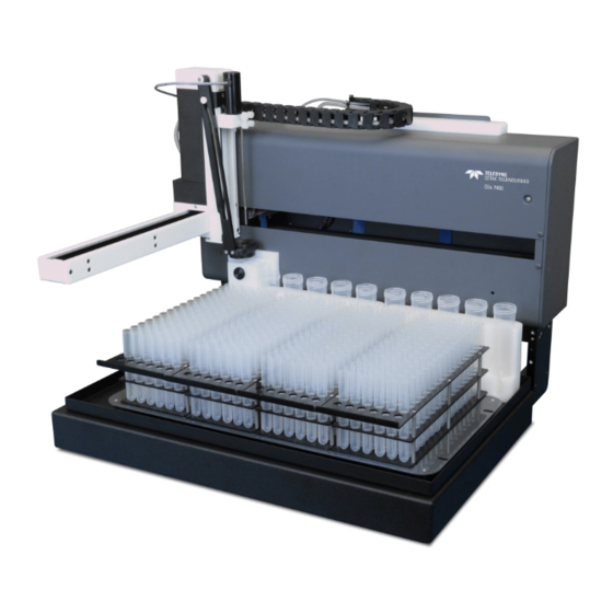
This document shows you how to install the hardware components of the Teledyne CETAC Oils 7400 homogenizing autosampler. See the Oils 7400 Series Operators Manual (on the CD) for instructions on installing the software and information on using and caring for the system. -
Page 3: Installing The Asx-7X00 Dashboard Software
USB Port Serial Ports Ethernet Port Auxiliary Port Power Switch Stirrer Connector Power Connector Peristaltic Pump (Oils) Peristaltic Pump (Coolants) Z-Drive Connector Rinse Station Fittings (Coolants) Rinse Station Fittings (Oils) Oils 7400 Autosampler—Back View IGURE Equipment Required You will need to choose a sample probe and sample racks appropriate for your application. The probe/stirrer block determines the spacing between the probe and stirrer;... -
Page 4: Mounting The Tray
Mounting the Tray Place the tray on the base of the autosampler. Make sure the locating pins on the tray fully seat into the locating holes in the base. Installing the Stirrer When the autosampler is used for oils, install the stirrer paddle. When the autosampler is used for coolants, the stirrer paddle should be removed (or replaced with the optional coated coolants stirrer paddle). -
Page 5: Installing And Adjusting The Sample Probe
Tighten the two thumbscrews. 7 Securing the Stirrer IGURE Installing and Adjusting the Sample Probe Choose the appropriate probe for your application. Locate the two thumbscrews which are supplied with the probe. Guide the probe straight down through the smaller hole in the Z-drive. Adjust the height of the probe so that the tip of the probe is level with the tip of the stirrer paddle. -
Page 6: Connecting The Rinse Station
Tighten the thumbscrews. 9 Installing the Probe IGURE Check the position of the sample tubing. Always position the sample transfer tubing so that it does not pull on the probe. The tubing should naturally curve away from the probe so that it won't rub or get caught. Be sure to check that the tubing will not be stretched and will not snag on an obstacle when the probe is moved to the far corner sample positions. - Page 7 the tubing firmly so that it completely covers the barb of the fitting. It helps to use your other hand to apply counter-pressure. Pumped Drain Arrangement Normally, the peristaltic pump channel which is closest to the autosampler chassis is used to pull liquid out of the rinse station and the channel which is farther from the autosampler is used to feed in the fresh rinse solution.
- Page 8 Connect one of the pieces of tubing from step 2 to the input (top) of the pump channel. Connect the other end of the tubing to the outlet (upper) fitting of the rinse station. The “Coolants” peristaltic pump should be connected to the blue side of the rinse station and the “Oils”...
-
Page 9: Assembling And Placing The Sample Vial Racks
Use an appropriate length of the tubing to connect the rinse solution source to the fitting at the top of this channel. From Rinse Solution Source To Waste Container 14 Completed Rinse Station Tubing for the Oils Side IGURE Assembling and Placing the Sample Vial Racks Some styles of sample vial racks are shipped unassembled. -
Page 10: Connecting The Autosampler To The Power Supply
One end of the sample transfer tubing is preconnected to the sample probe. The transfer tubing should be long enough so that it there will be no strain on the tubing connectors even when the sample probe is at the position farthest from the analytical instrument. -
Page 11: Connecting The Autosampler To The Host Computer
Connecting the Autosampler to the Host Computer Software on the host computer controls both the analytical instrument and the autosampler. The USB interface is the standard configuration. A virtual COM port is created so that the connection looks like a standard RS-232 serial port to the host PC software. If necessary, you may also use a serial (RS-232) cable. -
Page 12: Switching Between Coolant And Oil Samples
Switching Between Coolant and Oil Samples Move the rinse station to the appropriate position. The status LED on the front of the autosampler will show green for the oils position or blue for the coolants position. 16 Rinse station in coolants (left) and oils (right) position. IGURE Moving the rinse station will automatically switch to the appropriate peristaltic pump on the back of the autosampler.
Need help?
Do you have a question about the Oils 7400 Series and is the answer not in the manual?
Questions and answers