Table of Contents
Advertisement
Quick Links
Download this manual
See also:
Installation Manual
EN
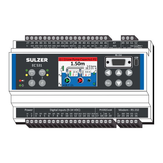
Equipment controller EC 531
27 28 29 30 31 32 33 34 35 36 37 38 39 40 41 42 43 44 45
V-
DO1 DO2 DO3 DO4 DO5 DO6 DO7 DO8 AO1 AO2 V+
Digital outputs (V+)
out (4-20 mA) in
EC 531
AUTO
AUTO
0
0
1
2
o P
w
r e
D
g i
a t i
i l
p n
t u
( s
- 9
V+
V-
DI1 DI2 DI3 DI4 DI5 DI6 DI7 DI8 DI9 DI10 DI11 DI12 DI13 DI14 AI7 V-
1
2
3
4
5
6
7
8
9
10 11 12 13 14 15 16 17 18 19 20
User guide
www.sulzer.com
47
AI1 AI2 AI3 AI4 V-
AI5 AI6
RJ45
Ethernet RS 485
Pt100/PTC
Esc.
4 3
V
D
) C
Pt100/Leak
AI8 V-
49 50 51 52
Bias +
+
-
Shld
Term.
Bias -
RS 232
USB
M
o
e d
m
-
S R
2
2 3
V-
RXD TXD RTS CTS
22 23 24 25 26
Advertisement
Table of Contents

Subscribe to Our Youtube Channel
Related Manuals for Sulzer EC 531


Summary of Contents for Sulzer EC 531
- Page 1 Equipment controller EC 531 27 28 29 30 31 32 33 34 35 36 37 38 39 40 41 42 43 44 45 49 50 51 52 Bias + DO1 DO2 DO3 DO4 DO5 DO6 DO7 DO8 AO1 AO2 V+...
- Page 2 The content of this manual is furnished for informational use only, is subject to change without notice, and should not be construed as a commitment by Sulzer. Sulzer assumes no responsibility or liability for any errors or inaccuracies that may appear in this book.
-
Page 3: Table Of Contents
Contents About this guide, audience and concepts Overview of the display symbols EC 531 panel ........................7 Symbols on the graphic display ..................8 1.2.1 Time and date ........................8 1.2.2 Level and the dynamic field ....................8 1.2.3 Outlet value on the display ....................8 1.2.4... - Page 4 APpendix: tables of guide line to the menus in EC 531 Quick status: system menu ....................50 Quick status: pump pit .....................50 Quick status: pump 1 and pump 2 ................... 51 Quick status: digital in and digital out ................53 Quick status: analog in and analog out ................53 Detailed status: system ....................54...
-
Page 5: About This Guide, Audience And Concepts
ABOUT THIS GUIDE, AUDIENCE AND CONCEPTS This guide describes the equipment controller EC 531. The equipment controller can either be used stand-alone or communicate values and conditions to a central SCADA system or a web based alarm and monitoring solution like AquaWeb from Sulzer. - Page 6 Text in italic is a description of text on the display or a description how you find your way through the menus by key strokes. Text in bold, is how you have to do a change of the settings in the EC 531 menu.
-
Page 7: Overview Of The Display Symbols
OVERVIEW OF THE DISPLAY SYMBOLS EC 531 is designed to control 1-2 pumps. It can operate a pump station stand alone and / or within a surveillance system together with some communication equipment. For configuration and opera- tor interaction, use the menus which can be selected using the arrow, Enter and Esc keys. With the AquaProg software, configuration and back up of settings can be stored on a PC. -
Page 8: Symbols On The Graphic Display
1.2 Symbols on the graphic display There are several symbols in the EC 531 display which are described below. Graphic display with level sensor Graphic display with start / stop floats First line Clock / Alarm Pit water level Outlet info Overflow sensor Pump info. -
Page 9: Pump Information Window
1.2.4 Pump information window The pump information window contains several symbols and not all of them are visible if there isn’t an alarm. Without any alarms or fault conditions, only Current and grey shaded Temperature and Leakage symbols are shown. Motor current Temperature Leakage... -
Page 10: Pump, Mixer, Pipe And Start / Stop Symbols
1.4 Pump, mixer, pipe and start / stop symbols The symbols are as follows: Pipe with pump reference • Animated flow when pump running in forward direction Pump symbol, will rotate when pump running Triangle can be: • Green – Non blocked •... -
Page 11: Status View
Escape to cancel and Symbolize the choices return to top screen which can be made with the arrow keys Use the left / right buttons to choose the insertion point. Use the up / down buttons to increase / de- crease a value or letter. -
Page 12: Entering The Main Menu And Set The Language
Entering the main menu and set the language Press up- or down arrow and following screen appears: Step down to Select language and press Enter. Press Enter again and use the down arrow to step between the languages, press Enter when your language of choice is highlighted. -
Page 13: Quick Status
Submenu Parameter Value Type/Passcode Manual start NO; YES Setting, Operator password Pump reversing NO, YES Setting, Operator password Fallen motor protect NO, YES Status value Reset motor prot. NO, YES Setting, Operator password Pump 1 Reset temp. prot. -OK-/[YES], -Tripped- Setting, Operator password State of M-0-A switch MANUAL, Pump not in auto, AUTO... - Page 14 This page is intentionally left blank.
-
Page 15: Setup The Ec 531
Every station will have its own unique configuration but the procedure to setup the station is similar. This chapter will guide you through the basic settings in the EC 531. Make note that this does not cover everything, you must take into account your prerequisites. - Page 16 In AquaProg: System settings Figure 2-1 Figure 2-2 Communication...
-
Page 17: Setup The Digital Inputs, Digital Outputs, Analog Inputs And Analog Outputs
2.2 Setup the digital inputs, digital outputs, analog inputs and analog outputs Set designated IO-functions according to the electrical wiring drawing. See your drawings of the station. Under Settings, Digital inputs; choose appropriate input according to list Table 2-1: Table 2-2: Digital inputs Digital outputs Run indication... -
Page 18: Setup The Pump Pit Parameters
Table 2-5: Table 2-6: Analog input 5-6 Analog input 7-8 Motor temperature Motor temperature Free choice Leakage Free choice In AquaProg: 2.3 Setup the pump pit parameters Table 2-7: Pit settings Station flow* Overflow Pit alarms Cleaning control Mixer control Drain pump control Motor protector auto-reset Level sensor check... - Page 19 Pump 1 and pump 2: Type of pump control: • Pump disable If using only one pump in the system; recommended to have pump 2 as disable • ON / OFF control A digital output starts the pump without any RS-485 communication to VFD or soft starter •...
-
Page 20: Common P1-P2
2.6 Set log settings and events There are 16 configurable analog log channels on the EC 531. It is recommended to the use the log channels in sequential order from channel 1, as having log channels disabled between active chan- nels will cause unnecessary data traffic to the surveillance system. -
Page 21: Set Up Communications To Surrounding Units Vfd, Soft Starters And Energy Meter
Modbus IDs and same communication parameters. EC 531 has BIAS-jumpers for high and low signals which by default are active on EC 531. If any of the other units also have this BIAS feature, it can be necessary to take out the BIAS-jumpers from EC 531. - Page 22 Drain pump A drain pump requires a start float to be connected to a digital input which is configured with the start float drain pump option. The settings for drain pump is to be found: Settings – Common P1-P2 – Drain pump control The drain pump runs only on time settings, there is no stop float for the drain pump.
-
Page 23: Detailed Description Of The Functions
How to setup cross reference table is explained here. Pump capacity calculation In EC 531 controller there are some crucial parameters which have to be set for accurate calculation of in / outflow and pump capacity. We will describe each parameter in general terms later in this doc- ument. - Page 24 Shape In the settings in EC 531 where it is possible to set the shape of the pit. To get an accurate calcula- tion at all levels, the pit shape must be defined as the calculation is different for different geometrical shapes.
- Page 25 When the controller has the level sensor installed and it’s correctly scaled, and the shape and size of the pit is known; the EC 531 can easily calculate the volume. Any changes in the level are directly proportional to the amount of in / outflow and to the volume in the pit.
- Page 26 Type in pump curve parameters in EC 531: In the menu of EC 531: Settings – Pump X (X = Pump 1–2) – Pump curve (QH) • Point 1 head (max) = X.XX m (ft.) There XX is manually replaced with new value •...
- Page 27 From pump curve, we can find the corresponding flow rate for each of; Hmax, Hmid and Hmin. (L) Point 1 Hmax tot. head 18.0 m (ft.) Point 1 Flow 8.2 l/s (GPM) (M) Point 2 Hmid tot. head 15.5 m (ft.) Point 2 Flow 14.4 l/s (GPM) (H) Point 3 Hmin tot.
- Page 28 A pump capacity calculation is performed every time the pump starts alone with no other pump running. If two pumps are running, the EC 531 will not perform any new calculation and will use the existing nominal pump capacity for the outflow calculation.
- Page 29 For a more accurate outflow calculation, the use of an outlet pressure sensor is recommended in the system. In this case the EC 531 will recalculate and adjust the outflow calculation based on the momentary level.
- Page 30 Above would give an estimated pump flow as at new conditions of approximately 26 l/s In practice A fictional station with two Sulzer pumps, XFP 150G CB1 50 Hz and a EC 531 controller. The data sheet for the pump:...
- Page 31 Data from graph Settings / Pump 1 / QH curve (pump curve) If not using an outlet pressure sensor – a value for Total head must be given; in this case: 20.1 m Data from specifications Other parameters needed for the flow calculation set-up: Settings / Station flow / Pit area Settings / Station flow / Meas.
- Page 32 Station flow settings. Settings of criteria for calculation of pump capacity The level settings will set boundaries for the possible levels in the basin where calculations can be con- ducted. The start delay time is a crucial setting, verify that the flow rate in the pipe has reached full velocity before the calculation is executed!
- Page 33 Example from a run sequence based on described set data in EC 531 shown in AquaWeb If the start delay time is set too short the calculated capacity is often too low. If the inflow value “jumps” at every pump sequence this is normally because of: wrongly set calculation parameters •...
-
Page 34: Overflow Flow Calculation
The analog input needs to have very good resolution to be able to measure the signal. The EC 531 does not have this problem, for example a sensor with the range of 10 meters the EC 531 has the resolution of < 0.7 mm. -
Page 35: Pump Alternation
- In Settings – Pump pit – Overflow you can type in the constant and exponents manually. There are two different exponents and two constants which can be set in EC 531 which are depen- dent on manufactures and nature of the weirs. - Page 36 Example 3-1: Continuous high inflow. A single pump can’t empty the pit. Start level pump 1 = 2.0 m Start level pump 2 = 3.0 m Stop level pump 1 = 1.0 m Stop level pump 2 = 1.5 m Method used Alt.
-
Page 37: Pump Reversing
Runtime alternation The pumps can also be alternated based on continuous runtime. At exceeded maximum run time the pump will stop and an alternative pump will be started. The pump will only stop if there is at least one alternative pump that is ready to run. Max number of pumps running If the piping system cannot take the pressure when two pumps are running there is a possibility to set the max number of pumps that are allowed to run at the same time. -
Page 38: Speed Controlled Pumps (Vfd)
The VFD is responsible for speeding up and down the pump. EC 531 doesn’t handle ramp times. The min and max frequency for the pump normally is set on the VFD. The PID controller also has adjustable min and max value for the output signal that can be used. - Page 39 Setup EC 531 for VFD pump(s) • In Settings – Pump x menu: Set Type of pump to [VFD manual speed or VFD PID con- trol or VFD best efficiently point] (see section 2.4 for explanations of different types). If a second VFD pump is used.
-
Page 40: Best Efficiency Point Pump Control
BEP in pump curve, the normal for most wastewater pump installations. EC 531 connects to most variable frequency drives with the RS 485 Fieldbus for monitoring and con- trol. With just a level sensor and a supported VFD attached, the pump will always run at the BEP. -
Page 41: Crash Log
8192 seconds (131072 data samples). The eight crash blocks are stored with a time stamp, ID no and alarm no for the trigger alarm. EC 531 is continuously saving raw analog input data every second. Following signals are saved:... - Page 42 EC 531 which connects via 3G to AquaWeb or a SCADA system. The communica- tions can be triggered by an event or set to log data values. EC 531 has support for CA 521 modem only for AquaWeb and sending text messages (SMS). Hayes settings normally works with default.
-
Page 43: Cross Reference Table
Negative values will give zero readout. Cross reference tables are only available to configure in AquaProg. In the menus of EC 531 you have NOTE! the possibility to activate or deactivate the table on each port separately. - Page 44 This page is intentionally left blank.
-
Page 45: Further Explanations Of Some Functions Of Analog- And Digital In- And Output Signals
FURTHER EXPLANATIONS OF SOME FUNCTIONS OF ANALOG- AND DIGITAL IN- AND OUTPUT SIGNALS In this chapter we shall explain some digital in- and outputs. Digital in: local mode Digital in: block operation Digital out: data register set point Digital out: logic IO Digital out: external reset alert Analog in: outlet pressure Analog out: data register and data register 2-compl. -
Page 46: Digital Out: Logic Io
AIN4 is register number 4; see figure 4-1 below. We configure the scale factor to 0.1 (i.e. the value in reg.4 is multiplied by 0.1 to get accurate value in engineering units). Above chart is an extract from the Modbus register manual for EC 531 – Figure 4-1 Analog inputs / output in engineering units. -
Page 47: Digital Out: External Reset Alert
In this example there are only three IO-bits involved. But there is an option to use up to four IO-bits. Table 4-1: Logic IO See the Modbus register manual regarding the IO-list 4.5 Digital out: external reset alert External reset alert is active when a digital input is defined as Alarm reset. In the settings for Alarm reset input, there is a time delay value which can be set. - Page 48 0.1 to get accurate value in engineering units). Figure 4-3 Above chart is an extract from the Modbus manual for EC 531 – Analog inputs / outputs in engi- neering units The function is setup in the menu of EC 531 under;...
-
Page 49: Appendix: Tables Of Guide Line To The Menus In Ec 531
APPENDIX: TABLES OF GUIDE LINE TO THE MENUS IN EC 531 Quick status: system Quick status: pump pit Quick status: pump 1 and pump 2 Quick status: digital in and digital out Quick status: analog in and analog out Detailed status: system... -
Page 50: Quick Status: System Menu
Quick status: system menu Table 5-1 shows the complete view for quick status under the submenu System Table 5-1: Quick status System Submenu Setting Value Comment EC 531 version 0.01 [Unitless] Status value EC 531 version Option 1 [Unitless] Status value Supply voltage 0.1 V DC... -
Page 51: Quick Status: Pump 1 And Pump 2
Submenu Submenu Value Comment Low pressure NO, YES Status value Overflow NO, YES Status value Sensor error NO, YES Status value Incor. lvl. low float NO, YES Status value Sensor error Incor. lvl. high float NO, YES Status value Level is not changing NO, YES Status value Pit level... - Page 52 Submenu Submenu Submenu Submenu Setting Value Comment Externally Unbalance NO, YES Status value blocked voltage Error NO, YES Status value blocked Fallen temp. NO, YES Status value prot. Pump NO, YES Status value blocking No run NO, YES Status value indication Fallen mo- NO, YES...
-
Page 53: Quick Status: Digital In And Digital Out
5.4 Quick status: digital in and digital out Table 5-4 shows the complete view for quick status under the submenu Digital in and Digital out Table 5-4: Quick status Digital in and Digital out Submenu Setting Comment Special Menu [Graphical representation] Status value Special Menu [Graphical representation]... -
Page 54: Detailed Status: System
5.6 Detailed status: system Table 5-6 shows the complete view for detailed status under the submenus System Table 5-6: Detailed status System Submenu Setting Value Comment EC 531 version 0.01 [Unitless] Status value EC 531 version Option 1 [Unitless] Status value Supply voltage 0.1 V DC... -
Page 55: Detailed Status: Pump Pit
5.7 Detailed status: pump pit Table 5-7 shows the complete view for detailed status under the submenus Pump pit Table 5-7: Detailed status Pump pit Submenu Submenu Setting Value Comment Pit level 0.01 m, 0.01 ft Status value Pit volume 1 l, 1 gal Status value Total... - Page 56 Submenu Submenu Setting Value Comment Total 1 [Unitless] Setting, System Password Today 1 [Unitless] Setting, System Password Drain pump Number of starts Repeats for 1-7 1 [Unitless] Setting, System Password days ago Terminal I/O status OFF, ON Status value Run indication NO, YES Status value Fallen motor protect...
-
Page 57: Detailed Status: Pump 1 And Pump 2
5.8 Detailed status: pump 1 and pump 2 Table 5-8 shows the complete view for detailed status under the submenus Pump 1 and Pump 2 Table 5-8: Detailed status Pump 1 and Pump 2 Submenu Submenu Setting Value Comment Tag name [Text String] Status value Pump control... -
Page 58: Detailed Status: Pid Regulator
Submenu Submenu Setting Value Comment Today 0.1 kWh Setting, System Password Energy consumption Repeats for 1-7 0.1 kWh Setting, System Password days ago Average 0.001 kWh/m , 1 kWh/Mgal Setting, System Password Today 0.001 kWh/m , 1 kWh/Mgal Setting, System Password Pump efficiency Repeats for 1-7 0.001 kWh/m... -
Page 59: Detailed Status: Analog Inputs
5.10 Detailed status: analog inputs Table 5-10 shows the complete view for detailed status under the submenus Analog inputs Table 5-10: Detailed status Analog inputs Submenu Setting Value Comment OFF, Pit level, Motor current, Outlet pressure, Vibrations, Xy- Signal function Status value lem MiniCas Sim, Outflow meter, Motor temperature, Free choice... -
Page 60: Detailed Status: Analog Outputs
Submenu Setting Value Comment OFF, Motor temperature, Signal function Status value Free choice, Leakage One or none of lines below, Depending on Port function Generic, Stator L1, Stator L2, Stator Measure point Status value L3, Upper bearing, Lower bearing Generic, Oil chamber, Motor Measure point Status value housing, Electr. -
Page 61: Detailed Status: Digital Outputs
Submenu Setting Value Comment Pulse channel 1, Pulse channel 2, Status value Object Pulse channel 3, Pulse channel 4 Object Pump 1, Pump 2, Mixer, Drain pump Status value Object Mixer, Drain pump Status value One or none of lines below, Depending on Port function Generic, Stator L1, Stator L2, Stator Status value Measure point... - Page 62 Submenu Submenu Setting Value Comment No. Error messages 1 [Unitless] Status value No. Checksum errors 1 [Unitless] Status value No. Overflows 1 [Unitless] Status value Service port (D-Sub) No. Parity errors 1 [Unitless] Status value No. Framing errors 1 [Unitless] Status value No.
-
Page 63: Detailed Status: Field Bus Modules (Rs 485)
Submenu Submenu Setting Value Comment Ethernet port (TCP/IP) No. OK messages 1 [Unitless] Status value No. Error messages 1 [Unitless] Status value Ethernet port (TCP/IP) No. Checksum errors 1 [Unitless] Status value Port status [Graphical representation] Status value Signal 0-31 (99=NA) 1 [Unitless] Status value Local IP address... -
Page 64: Settings: Alarm Legend
Submenu Submenu Setting Value Comment PM Connected -Disconnected-, -Connected- Status value PM Com. error -OK-, -Error- Status value Current 0.1 A Status value Line current L1 0.1 A Status value Line current L2 0.1 A Status value Line current L3 0.1 A Status value Pwr.mon.1 Pwr.mon.2... -
Page 65: Settings: System
Ackn. all alarms w. reg 333 NO, YES Setting, System Password Power fail Digital Alarm, see legend System Alarms High PCB temp. EC 531 Analog Alarm, see legend Low supply voltage Analog Alarm, see legend System Alarms Personnel alarm Analog Alarm, see legend... - Page 66 Submenu Submenu Setting Value Comment Exponent 1 0.0001 [Unitless] Setting, System Password Constant 1 0.0001 [Unitless] Setting, System Password Overflow Exponent 2 0.0001 [Unitless] Setting, System Password Constant 2 0.0001 [Unitless] Setting, System Password High level Analog Alarm, see legend Low level Analog Alarm, see legend Digital Alarm, see legend...
-
Page 67: Settings: Pump 1 And Pump 2
Submenu Submenu Setting Value Comment At high-level float OFF, ON Setting, System Password Level at high float 0.01 m, 0.01 ft Setting, System Password Max deviation +/- 0.01 m, 0.01 ft Setting, System Password At low-level float OFF, ON Setting, System Password Level-sensor check Level at low float 0.01 m, 0.01 ft... - Page 68 Submenu Submenu Setting Value Comment Random start 0.01 m, 0.01 ft Setting, Operator Password range+- Start level h. tariff 0.01 m, 0.01 ft Setting, Operator Password Start/stop levels Stop level h. tariff 0.01 m, 0.01 ft Setting, Operator Password Random start 0.01 m, 0.01 ft Setting, Operator Password range+-...
- Page 69 Submenu Submenu Setting Value Comment Generic NO, YES Setting, System Password Oil chamber NO, YES Setting, System Password Leakage Motor housing NO, YES Setting, System Password Electr. con. box NO, YES Setting, System Password Block pump on alarm High motor current NO, YES Setting, System Password Fallen motor protect...
-
Page 70: Settings: Common P1 - P2
5.20 Settings: common P1 – P2 Table 5-20 shows the complete list of Common P1-P2 settings Table 5-20: complete list of common P1-P2 settings, under the menu item Setting – Common P1-P2 Submenu Submenu Setting Value Comment Log pump events NO, YES Setting, System Password Exercise P1... - Page 71 Submenu Submenu Setting Value Comment Under voltage NO, YES Setting, System Password Power Unbalance voltage NO, YES Setting, System Password Manual rst on Pump blocking NO, YES Setting, System Password hi p temp Pwr mon. block Setting, System Password off delay Function OFF, ON Setting, System Password...
-
Page 72: Settings: Pid Regulator
5.21 Settings: PID regulator Table 5-21 shows the complete list of settings of the PID regulator Table 5-21: complete list of settings of the PID regulator, under the menu item Setting – PID regulator Setting Value Comment Setpoint 0.01 m, 0.01 ft Setting, System Password Setpoint high tariff 0.01 m, 0.01 ft... -
Page 73: Settings: Analog Logging
Set frequency, Actual frequency, Motor power, Motor voltage, Torque, Out- Log channel 1-16 flow meter, Total head, PCB temperature EC 531, BEP frequency, BEP efficiency Closed, Actual value, Average Log function Setting, System Password value, Min value, Max value... -
Page 74: Settings: Analog Inputs
5.24 Settings: analog inputs Table 5-24 shows the complete list of settings of the Analog inputs Table 5-24: complete list of settings of the analog inputs, under the menu item Setting – Analog inputs Submenu Submenu Setting Value Comment OFF, Pit level, Motor current, Outlet pressure, Vibrations, Signal function... - Page 75 Submenu Submenu Setting Value Comment Set sensor/ Settings Digital Alarm, see legend cable alarm Scaling 0% 0.001 mA Setting, System Password Scaling 100% 0.001 mA Setting, System Password Filter constant Setting, System Password Settings Zero offset 0.001 mA Setting, System Password Dead band 0.1% Setting, System Password...
- Page 76 Submenu Submenu Setting Value Comment Generic, Stator L1, Stator L2, Stator Measure point Setting, System Password L3, Upper bearing, Lower bearing Pt100 (temp. sensor), Sensor type Setting, System Password PTC/Bimetal switch One or none of lines below, Depending on Port function Object Pump 1, Pump 2 Setting, System Password...
-
Page 77: Settings: Analog Outputs
Submenu Submenu Setting Value Comment Filter constant Setting, System Password Zero offset 0.1 ºC, 0.1 ºF Setting, System Password Settings Set sensor/ Digital Alarm, see legend cable alarm One or none of lines below, Depending on Port function Designation [Text String] Setting, System Password Select units [Text String]... -
Page 78: Settings: Digital Inputs
Submenu Submenu Setting Value Comment Scaling 0% 0.1 l/s/ha, 0.1 in/h Setting, System Password Settings Scaling 100% 0.1 l/s/ha, 0.1 in/h Setting, System Password Scaling 0% 0.1 kW Setting, System Password Settings Scaling 100% 0.1 kW Setting, System Password Scaling 0% 0.1 m /h, 1 GPM Setting, System Password... -
Page 79: Settings: Digital Outputs
Submenu Submenu Setting Value Comment Alarm settings Digital Alarm, see legend Alarm text [Text String] Setting, System Password Pump 1, Pump 2, Object Setting, System Password Mixer, Drain pump Object Mixer, Drain pump Setting, No Password DI14 NO Normally open, Normally open/closed Setting, System Password NC Normally closed... -
Page 80: Settings: Communication
Submenu Submenu Setting Value Comment Data register 1 [Unitless] Setting, System Password Setpoint on 1 [Unitless] Setting, System Password Settings Setpoint off 1 [Unitless] Setting, System Password Setpoint delay Setting, System Password NO Normally open, Normally open/closed Setting, System Password NC Normally closed Event Trigger OFF, ON... - Page 81 Submenu Submenu Setting Value Comment Modbus RTU, Protocol type Setting, System Password Modbus TCP Protocol ID 1 [Unitless] Setting, System Password Settings GPRS Message timeout Setting, System Password Cross reference OFF, ON Setting, System Password Modbus RTU, Protocol type Setting, System Password Modbus TCP Protocol ID 1 [Unitless]...
-
Page 82: Settings: Field Bus Modules (Rs 485)
5.29 Settings: field bus modules (RS 485) Table 5-29 shows the complete list of settings of the Field bus modules (RS 485) Table 5-29: complete list of settings of the field bus modules (RS 485), under the menu item Setting – Field bus modules (RS 485) Submenu Submenu Setting... -
Page 83: Settings: Select Language
Submenu Submenu Setting Value Comment None, P1000 <= Model* (*YASKAWA) Setting, System Password 11KW, P1000 > 11KW Monitor, & Con- trol on/off, and Modbus control Setting, System Password Manual speed, and Auto speed Ackn. alarm NO, YES Setting, System Password reset drive Max set fre- 0.1 Hz... - Page 84 Sulzer Pump Solutions Ireland Ltd., Clonard Road, Wexford, Ireland Tel. +353 53 91 63 200, Fax +353 53 91 42 335, www.sulzer.com Copyright © Sulzer Ltd 2018...
Need help?
Do you have a question about the EC 531 and is the answer not in the manual?
Questions and answers