
Subscribe to Our Youtube Channel
Related Manuals for Jay electronique RS Series

Summary of Contents for Jay electronique RS Series
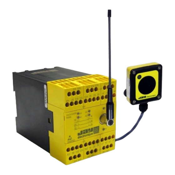
- Page 1 Series Wireless enabling handle RSRB RSEP RSCP Installation and User Manual - TRANSLATED IN ENGLISH FROM ORIGINAL FRENCH VERSION - 332190D – Doc ref. : 28.04.2014 Page 1 / 49...
-
Page 2: Table Of Contents
TABLE OF CONTENTS 1 Safety rules and general safety guidelines ........5 2 Product identification data ..............5 3 Theory of operation ................6 4 Check of functions, initial start-up ........... 7 « Ex-FACTORY » parameters ...................... 7 Setting the wireless enabling handle into service ..............7 Setting the charger into service .................... - Page 3 5.10 Handle locking function ......................31 5.10.1 Locking the handle ..............................31 5.10.2 Activating/deactivating the locking function ......................31 5.11 Receiver wiring examples ...................... 32 5.11.1 Wiring diagram for configuration without access control ..................32 5.11.2 Wiring diagram for configuration with access control by gate .................. 32 5.11.3 Wiring diagram for configuration with access control by safety light barrier.............
- Page 4 Reference serial model submitted to approval: April 2014 332190D – Doc ref. : 28.04.2014 Page 4 / 49...
-
Page 5: Safety Rules And General Safety Guidelines
1 Safety rules and general safety guidelines Under the terms of the European Machinery Directives, the wireless enabling handle is understood as a control unit and as a safety component used to stop a system. All applicable safety rules must be observed when installing and using the wireless enabling handle. -
Page 6: Theory Of Operation
3 Theory of operation The receiver (R) is integrated in the machine control unit. The wireless enabling handle (P) transmits, by radiowave, the trigger operating request (G) and possible commands generated using the buttons (B). The receiver (R) enables (or not) operation (F) of the machine (M) and transfers the commands (O) assigned to the buttons. -
Page 7: Check Of Functions, Initial Start-Up
4 Check of functions, initial start-up This section is aimed at familiarising you with the product. Detailed procedures are given to allow you to simulate operation of the equipment in its « ex-factory » configuration. 4.1 « Ex-FACTORY » parameters Operating mode ........ -
Page 8: Setting The Charger Into Service
4.3 Setting the charger into service • Step 1 Connect a 24VDC (+/- 5 %) stabilised power supply to the – (ground) and + (+24Vdc) terminals. Pairing button: 24 VDC power supply This button ensures pairing of the handle with «... -
Page 9: Warning Regarding The Battery Of The Enabling Handle
There is a risk of explosion if battery is replaced by a battery of an incorrect type. Only the battery intended for the enabling handle and supplied by JAY Electronique is suitable Only the charger ref. :RSCP from JAY Electronique is suitable for recharging the battery of the enabling handle. -
Page 10: Setting Up The Product
4.5 Setting up the product Test wiring: does not take account of your application : • Step 1 Prepare a 24VDC (+/- 5 %) stabilised power supply, 500 mA min. Prepare a pushbutton, for the reset function. • Step 2 Wire the receiver as follows : Shunt the terminal pairs [S11-S12], [S13-S14], [S21-S22], [S24-S23] and [Y1-Y2] Connect the terminals S31, S32, S33 and S34 to the charger... -
Page 11: Testing The Unit
4.6 Testing the unit Button B4 Button B3 Display Button B1 Button B2 3-position trigger (1) released (2) activated (3) clenched 2-position trigger (1) released (2) activated • Step 1 Place the handle on the charger. The green indicator light on the charger comes on. If not, check that the handle is paired with the charger. -
Page 12: Setting The Product Into Service
5 Setting the product into service Experience has shown that functional reliability basically depends on : the quality of the electrical power supply and the associated protection circuits ; the characteristics of the components connected to the receiver. the position of the reception antenna. the configuration and wiring of the various components 5.1 Electrical power supply, installation and wiring Final wiring in the receiver cabinet and of the charger must only be performed with the power shut down. -
Page 13: Intervention Mode And Operation Of Enabling Handle
5.3 Intervention mode and operation of enabling handle The intervention mode and operation of the product depend on the needs of the application. Intervention mode The wireless enabling handle can be used on machines in the following modes : « Monitoring - Diagnostic» «... -
Page 14: Conditions For Intervention In « Manual Control » Mode
5.3.2 Conditions for intervention in « manual control » mode Safety condition in this intervention mode This mode satisfies the requirements of standard NF EN12100-2 §4.11.8 « Guidelines relative to manual control ». This mode is possible insofar as control of the movement using the control buttons associated to action on the handle trigger is sufficient to stop the equipment if necessary. -
Page 15: Configuration Of Enabling Handle Operating Mode
5.3.4 Configuration of enabling handle operating mode The wireless enabling handle operating mode can be configured using the Dialog RSP PC software supplied with the handle. This software is used to : Configure the handle in « 4 control buttons » or « function selection » operating mode. Modify the content of the screen display on the handle by loading or creating new pictograms. -
Page 16: Adjusting The Machine Area Access Time
5.3.6 Adjusting the machine area access time. The machine area access time and the time during which the gate or safety light barrier is inhibited to allow intervention in a machine area are configurable using the 2 « A » selectors on the receiver. Important : The 2 «... -
Page 17: Receiver : Operation And Wiring
5.4 Receiver : operation and wiring 5.4.1 Operation and wiring of function outputs The receiver is equipped with 6 solid state outputs (100 mA max). Assignment of the enabling handle buttons (B1 to B4) with respect to the outputs depends on the operating mode selected using the RSP configuration software. Assignment of receiver outputs in «... -
Page 18: Operation And Wiring Of Safety Relays K1-K2
5.4.2 Operation and wiring of safety relays K1-K2. The safety stop chain is cut out by safety relays K1 and K2 (internal to receiver) which control the contacts accessible by terminals 22-23 and 32-33. The state of relays K1 and K2 depends : on the position of the trigger (table 1), possible faults detected, and possible radio link losses. -
Page 19: Monitoring Of Main Contactor : Operation And Wiring
5.4.3 Monitoring of main contactor : operation and wiring Input « Y1-Y2 » is used to monitor the state of the contactor(s) connected to the K1-K2 safety outputs. The state of the contactor contact(s) wired to input Y1-Y2 must be closed in order to reset the receiver. Note : If this input is not used, wire a jumper across inputs Y1 and Y2. -
Page 20: Wiring Of A Wired Safety Shutdown Device
5.4.5 Wiring of a wired safety shutdown device. The external safety shutdown devices (wired safety shutdown palmswitches ...) must be wired to the « Emergency stop » inputs. To do so, you must use external safety shutdown devices comprising two redundant contacts. One of the contacts must be connected across terminals S11-S12, and the other across S13-S14 (fig 2). -
Page 21: Wiring Of An Equipment With Area Access Protection
5.4.7 Wiring of an equipment with area access protection The enabling handle can be used with machinery located in an area with protected accesses, or with machinery for which access is not protected. On equipment with protected access, the wireless enabling handle can be used to generate access requests and can control the access to a protected area : - The accesses must be equipped with a system used to detect passage of a person. -
Page 22: Wiring Of An Equipment Without Area Access Protection
5.4.8 Wiring of an equipment without area access protection If the equipment does not have a peripheral protection system with a machine area access feature, you must connect jumpers across the machine area access monitoring inputs, S21-S22 and S23-S24. 5.4.9 Wiring of “handle on charger” detection function This function must be wired to inhibit the enabling handle when it is not used. -
Page 23: Wiring Of Indicator Light Column On Receiver
Diagram 2 : Wiring for configuration with machine area access (example with gate) 5.4.10 Wiring of indicator light column on receiver We strongly recommend that you wire an indicator light column on the receiver. The column will indicate the status of the equipment and of the wireless enabling handle. -
Page 24: Wiring Of Receiver Power Supplies
5.4.11 Wiring of receiver power supplies This operation should be performed at the end of the wiring procedure. 332190D – Doc ref. : 28.04.2014 Page 24 / 49... -
Page 25: Charger : Wiring And Management
5.5 Charger : wiring and management. 5.5.1 Association of charger and wireless enabling handle If the charger has not been associated to its handle, refer to the section entitled « Setting the charger into service ». 5.5.2 Wiring of charger power supply To supply the charger, refer to the section entitled «... -
Page 26: Language Selection
5.6 Language selection Several dialog languages are available with the enabling handle display. The language is chosen by simultaneously pressing buttons B3 and B4. • Pick up the handle, leaving the trigger in the released position (1). • *Simultaneously press buttons B3 and B4 ... -
Page 27: Radio Working Frequency
5.7 Radio working frequency 5.7.1 Selection of radio working frequency. To limit unintentional cut-outs linked to radio interference, it is important to choose a radio channel (frequency) which is available. Use the following guidelines in making your choice : - Consider the point of installation of the receiver as the centre of the radio link ; - Estimate the maximum distance «... -
Page 28: Reading The Working Frequency
5.7.3 Reading the working frequency. • Pick up the handle, leaving the trigger in the released position. • Simultaneously press buttons B1 and B2 The radio channel programmed is displayed • Press EXIT (B2) to exit. Note : The receiver working frequency is not accessible. 5.7.4 Changing the working frequency 2-position trigger 3-position trigger... -
Page 29: Radio Transmit Power
5.8 Radio transmit power 5.8.1 Transmit power selection We recommend that you increase the power when the desired radio ranges are great or when radio interferences produce accidental cut-outs. It is preferable to decrease the power when working at limited ranges and where several systems are working together within a radius of less than 10m. -
Page 30: Identity Code
5.9 Identity code 5.9.1 Identity code selection The identity code is used to pair the handle and its receiver. To communicate with a receiver RSRB, the handle must be programmed with the same identity code. 5.9.2 Reading the identity code, software version and SIM card serial number 3-position trigger 2-position trigger (1) released... -
Page 31: Handle Locking Function
5.10 Handle locking function 5.10.1 Locking the handle You can protect your installation parameters (frequency, transmit power) against handling mistakes by locking the handle. We recommend that you activate this protection function on completion of your installation procedure. Locking the handle will protect you against accidental changes, but will not prevent you from reading the identity code and the frequency channel, or from running a scan to realign a receiver on the same frequency channel used in the enabling handle. -
Page 32: Receiver Wiring Examples
5.11 Receiver wiring examples 5.11.1 Wiring diagram for configuration without access control The receiver does not manage machine area access. In addition to the radio input associated to the enabling handle, an emergency stop can be wired to the receiver. Otherwise, you must wire 2 jumpers across S11-S12 and S13-S14. -
Page 33: Wiring Diagram For Configuration With Access Control By Safety Light Barrier
5.11.3 Wiring diagram for configuration with access control by safety light barrier Reminder : The handle can only be configured in « 4 control buttons » mode. To monitor access to the machine area, it is necessary to wire the outputs of the safety light barrier on inputs S21-S22 and S23-S24. -
Page 34: Diagnostic
6 Diagnostic In the event of a problem, the handle and the receiver will indicate a fault detected by an error message. On the wireless enabling handle, the error messages are shown on the display screen. On the receiver, the error messages are indicated by indicator lights V1 to V4. 6.1 Faults communicated by wireless enabling handle Message shown on display, in French and... -
Page 35: Faults Communicated By Receiver
6.2 Faults communicated by receiver To indicate faults, the receiver uses 4 indicator lights, V1 to V4. The 2 white indicator lights, « V1 and V2 », indicate the status of the receiver safety functions. The red and green indicator lights, « V3 and V4 », indicate the status and processing of radio signal reception. V1 status V2 status Error detected... -
Page 36: V3 And V4 Led Status
One of the emergency stop inputs is Check wiring of emergency stop or 7 flashes Error on input(s) incorrectly wired gate inputs One of safety relays K1 or K2, or 8 flashes 8 flashes Safety relay error Return to factory associated control circuit, is faulty Return loop to terminals Y1-Y2 not Check loop Y1 and Y2 and contacts... -
Page 37: Servicing
Level 2 : Level 2 spare parts are only accessible to customers who have completed a level 2 training course, and to the JAY Electronique service stations. 8.1 Setting a backup handle into service Step 1 : Open the broken or faulty handle. -
Page 38: Warranty
The JAY Electronique responsibility during the warranty period is limited to material and construction defects. This warranty comprises repair in the JAY Electronique workshops or replacement, free of charge, of parts recognized to be defective following expert inspection by the JAY Electronique Technical Department. -
Page 39: Appendices
10 Appendices 10.1 Dimensions of components (mm) Wireless enabling handle RSEP Charger RSCP Receiver RSRB Infrared module UDF (for "IR start-up" option) Plug-in BNC antennas Voltage adapter RSCU 230VAC/24VDC 332190D – Doc ref. : 28.04.2014 Page 39 / 49... -
Page 40: Technical Characteristics
10.2 Technical characteristics 10.2.1 Wireless enabling handle RSEP Mechanical and environment withstand characteristics Housing material : Two-material plastic Protection index : IP 54 Weight (with battery) : 340 g Operating temperature range : -20 °C to + 50 °C Storage temperature range : -20 °C to + 45 °C Charging temperature range : 0 °C to + 35 °C Electrical and radio characteristics Power supply : Li-Ion battery... -
Page 41: Receiver Rsrb
10.2.3 Receiver RSRB Mechanical and environment withstand characteristics Housing material : Plastic Protection index : IP 40 Weight : 500 g Operating temperature range : 0 °C to + 50 °C Storage temperature range : - 30 °C to + 70 °C Connection : Screw terminals for wires 0.08²... -
Page 42: Indicator Lights And Assignment Of Receiver Outputs
10.3 Indicator lights and assignment of receiver outputs Removable connection block, screw terminals Red ind. light V3 "Wrong identity code or diagnostic" White ind. lights V1 and V2 "Safety module status" BNC connector For antenna extensions and BNC antennas Green ind. lights K1 and K2 "Safety relay status"... -
Page 43: Ir Start-Up» Option
10.4 «IR start-up» option The start-up zone for an equipment, and the equipment’s identification, can be secured by an IR validation on start-up. To start the equipment, the operator must be inside the IR transmit zone of the UDF module (referred to as the «Start- up zone») and actuate the trigger on the handle. -
Page 44: Procedures
11 Procedures 11.1 Accessing a machine area in « monitoring - diagnostic » mode The enabling handle is on its charger and the machine is in service. The green indicator light on the indicator light column is on steady. Remove the handle from its charger. The orange indicator light on the indicator light column flashes (duration programmed by «... -
Page 45: Accessing A Machine Area In « Manual » Mode
11.2 Accessing a machine area in « manual » mode Preamble In "manual" mode, the safety relay of the receiver will be wired so as not to cause an emergency stop, but a "cycle stop" of the machine. In this mode, the enabling handle is used to make an adjustment or a test of the machine after a maintenance operation. -
Page 46: Environmental Data
12 Environmental data According to EN 60947-1:2007 +A1:2011 clause 5.3, page 61: NOTICE : This product has been designed for environment A. Use of this product may cause unwanted electromagnetic disturbances in which case the user may be required to take adequate mitigation measures. The altitude does not significantly affect the characteristics of RSRC receiver up to 2000 m. -
Page 47: Ce Declarations Of Conformity
18 CE Declarations of conformity 18.1 RSEP40-x / RSCP-x / RSRBx4xx-x and RSEP41-x / RSCP-x / RSRBx4xx-x 332190D – Doc ref. : 28.04.2014 Page 47 / 49... -
Page 48: Rsep4A-X / Rscp-X / Rsrbx4Xx-X And Rsep4B-X / Rscp-X / Rsrbx4Xx-X
18.2 RSEP4A-x / RSCP-x / RSRBx4xx-x and RSEP4B-x / RSCP-x / RSRBx4xx-x 332190D – Doc ref. : 28.04.2014 Page 48 / 49... - Page 49 IMPORTANT When the wireless enabling handle is placed on its charger, radio transmission is stopped and its trigger is INACTIVE ! Stop Equipment stopped and secured In area Intervention in area with handle Equipment operating Appendix to installation manual 332190D 332190D –...
Need help?
Do you have a question about the RS Series and is the answer not in the manual?
Questions and answers