Sign In
Upload
Manuals
Brands
Jay Electronique Manuals
Microphone system
RS Series
Jay Electronique RS Series Manuals
Manuals and User Guides for Jay Electronique RS Series. We have
2
Jay Electronique RS Series manuals available for free PDF download: Installation And User Manual
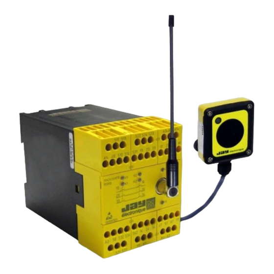
Jay Electronique RS Series Installation And User Manual (49 pages)
Wireless enabling handle
Brand:
Jay Electronique
| Category:
Microphone system
| Size: 4 MB
Table of Contents
Table of Contents
2
1 Safety Rules and General Safety Guidelines
5
2 Product Identification Data
5
3 Theory of Operation
6
4 Check of Functions, Initial Start-Up
7
Ex-FACTORY » Parameters
7
Setting the Wireless Enabling Handle into Service
7
Setting the Charger into Service
8
Warning Regarding the Battery of the Enabling Handle
9
Setting up the Product
10
Testing the Unit
11
5 Setting the Product into Service
12
Electrical Power Supply, Installation and Wiring
12
Receiver
12
Charger
12
Receiver Antenna
12
Intervention Mode and Operation of Enabling Handle
13
Conditions for Intervention in «Monitoring - Diagnostic» Mode
13
Conditions for Intervention in « Manual Control » Mode
14
Summary of Conditions for Intervention on Machine
14
Configuration of Enabling Handle Operating Mode
15
Receiver : Selecting the Program
15
Adjusting the Machine Area Access Time
16
Receiver : Operation and Wiring
17
Operation and Wiring of Function Outputs
17
Operation and Wiring of Safety Relays K1-K2
18
Monitoring of Main Contactor : Operation and Wiring
19
Reset Button : Wiring and Management
19
Wiring of a Wired Safety Shutdown Device
20
Wiring of a Machine Area Access Authorisation Request Function
20
Wiring of an Equipment with Area Access Protection
21
Wiring of an Equipment Without Area Access Protection
22
Wiring of "Handle on Charger" Detection Function
22
Wiring of Indicator Light Column on Receiver
23
Wiring of Receiver Power Supplies
24
Charger : Wiring and Management
25
Association of Charger and Wireless Enabling Handle
25
Wiring of Charger Power Supply
25
Taking the Wireless Enabling Handle off Its Charger
25
Setting the Wireless Enabling Handle on Its Charger
25
Language Selection
26
Radio Working Frequency
27
Selection of Radio Working Frequency
27
List of Channels and Radio Frequencies (in Accordance with Enabling Handle Model)
27
Reading the Working Frequency
28
Changing the Working Frequency
28
Radio Transmit Power
29
Transmit Power Selection
29
The Average Range will Depend on the Product Environment (Presence of Metal Obstacles
29
Reading/Changing the Transmit Power
29
Identity Code
30
Identity Code Selection
30
Reading the Identity Code, Software Version and SIM Card Serial Number
30
Changing the Identity Code
30
Handle Locking Function
31
Locking the Handle
31
Activating/Deactivating the Locking Function
31
Receiver Wiring Examples
32
Wiring Diagram for Configuration Without Access Control
32
Wiring Diagram for Configuration with Access Control by Gate
32
Wiring Diagram for Configuration with Access Control by Safety Light Barrier
33
6 Diagnostic
34
Faults Communicated by Wireless Enabling Handle
34
Faults Communicated by Receiver
35
V3 and V4 LED Status
36
7 Servicing
37
Servicing the Wireless Enabling Handle
37
Servicing the Charger
37
8 Maintenance
37
Setting a Backup Handle into Service
37
Replacing a Receiver
37
Replacing a Charger
37
9 Warranty
38
10 Appendices
39
Dimensions of Components (MM)
39
Technical Characteristics
40
Wireless Enabling Handle RSEP
40
Charger RSCP
40
Receiver RSRB
41
Indicator Lights and Assignment of Receiver Outputs
42
IR Start-Up» Option
43
Positioning the IR Module UDF
43
Connecting the UDF Module to the Receiver
43
11 Procedures
44
Accessing a Machine Area in « Monitoring - Diagnostic » Mode
44
Accessing a Machine Area in « Manual » Mode
45
12 Environmental Data
46
13 Residual Risks
46
14 Foreseeable Misuse
46
15 Contraindications
46
16 Waste Recycling and Management
46
17 Manufacturer Information
46
18 CE Declarations of Conformity
47
RSEP40-X / RSCP-X / Rsrbx4Xx-X and RSEP41-X / RSCP-X / Rsrbx4Xx-X
47
RSEP4A-X / RSCP-X / Rsrbx4Xx-X and RSEP4B-X / RSCP-X / Rsrbx4Xx-X
48
Advertisement
Jay Electronique RS Series Installation And User Manual (44 pages)
wireless safety logic signal transmission system
Brand:
Jay Electronique
| Category:
Receiver
| Size: 3 MB
Table of Contents
Table of Contents
2
1 Safety Rules and General Precautions
4
2 Identification of Components
5
3 Product Operating Principle
6
4 Check of Functions, Initial Startup
7
Parameters on Delivery « Ex-FACTORY
7
Preliminary Steps before Installation
8
Safety Transmitter RSEF : Terminal Strip and Test Wiring Diagram
8
Transmitter Test Wiring (Does Not Take Account of Application)
8
Safety Receiver RSRD: Terminal Strip and Test Wiring Diagram
10
Assignment of Inputs Connected to Transmitter RSEF and Static Outputs of Receiver RSRD
11
Power Supply of Outputs
11
Receiver Test Wiring (Does Not Take Account of Application)
11
System Test before Installation
12
Wiring the Transmitter RSEF
19
Example Connection of a Safety Light Curtain on Transmitter Safety Input
19
Example with Static Inputs (PLC for Example)
19
Typical Wiring Diagram
19
Wiring the Receiver RSRD
20
Conductor Wire Sections to be Observed
20
Multi-Strand Wires: Use of Wire End Ferrules Is Mandatory
20
Usa/Canada Specifications for Installation and Conductor Wires to be Used
20
Enabling Handle : Wiring and Operating Mode
21
Monitoring of Main Contactors
21
Operation of Safety Relays RS1-RS2 of Receiver RSRD
21
Example with Wired Emergency Stop Palmswitch
22
Typical Wiring Diagram for Receiver RSRD
22
Example with Contactor Monitoring Function
23
Example with Wired Enabling Handle
23
Wiring an Indicator Light Column
24
5 Modifying the Product Configuration
13
Transmitter RSEF
13
General Process
13
Configuring the Radio Transmit Frequency
14
Radio Channel Programming Table for 433-434Mhz Range
14
Radio Channel Programming Table for 911-918Mhz Range
15
Configuring the Check Function for Inputs E1 to E10 on Power up
16
Configuring the Restart Mode of Transmitter RSEF
17
Receiver RSRD
18
General Process
18
Safety Delay
18
6 Wiring the Components
19
Positioning the Components and Antennas
26
7 Instructions for Safe Installation and Commissioning
25
General Information
25
Transmitter RSEF
25
Receiver RSRD
25
8 Options
27
Switch RF Control Option
27
Wiring the RF Switch
27
9 Antennas
28
433-434MHZ Bands
28
911-918Mhz Bands
29
10 Diagnosis
30
Transmitter RSEF : Messages Given by Indicator Lights V1 and V2
30
Receiver RSRD : Error Messages
31
11 Servicing
32
12 Maintenance
32
Replacement of a Transmitter RSEF
32
Inspection and Servicing of the Receiver RSRD
33
13 Warranty
34
14 FCC Rules & Regulations (Federal Communications Commission)
35
15 IC Regulations (Industry Canada)
36
16 Appendices
37
Component Dimensions (MM)
37
Technical Characteristics
38
Transmitter RSEF
38
Receiver RSRD
39
Environmental Data
40
Safety Related Parameters
40
Characteristic Data According to IEC 61508-1 Till -7 and IEC 62061:2005
40
Characteristic Data According to en ISO 13849-1:2015
41
RSEF Transmitter Case Thermal Capability
42
Residual Risks
42
Forseeable Misuse
42
Warning, Avoid any Mutual Disturbance
42
Countries Limitation of the Use
42
Manufacturer Information
42
17 Declaration of Conformity
43
Waste Recycling and Management
42
Products References
42
Advertisement
Related Products
Jay Electronique RSEP4A Series
Jay Electronique RSEP4B Series
Jay Electronique RSEP40 Series
Jay Electronique RSCP Series
Jay Electronique RSRB*4 Series
Jay Electronique RSEP41 Series
Jay Electronique RADIOSAFE Series
Jay Electronique RSEF
Jay Electronique RSRD
Jay electronique ISE
Jay Electronique Categories
Remote Control
Microphone system
Control Systems
Receiver
Transmitter
More Jay Electronique Manuals
Login
Sign In
OR
Sign in with Facebook
Sign in with Google
Upload manual
Upload from disk
Upload from URL