Advertisement
Quick Links
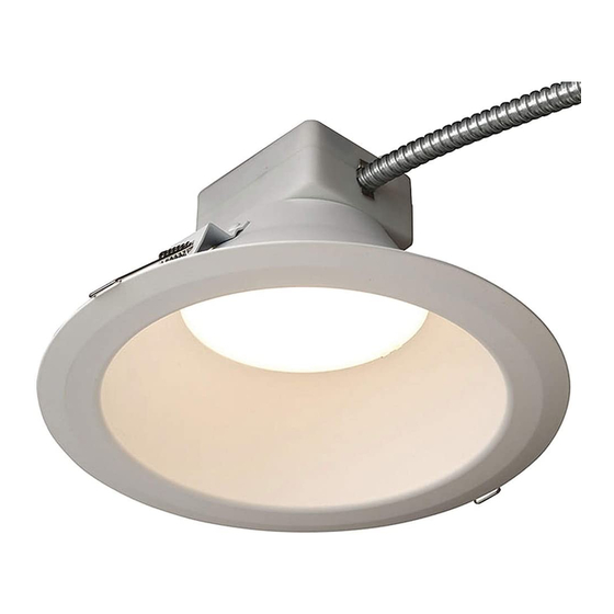
Lumination
RC/LRC/RX/LRX Series - New Construction Frame
BEFORE YOU BEGIN
Read these instructions completely and carefully.
RISK OF ELECTRIC SHOCK
• Turn power off before inspection, installation or removal.
• Properly ground electrical enclosure.
RISK OF FIRE
• Follow all NEC and local codes.
• Use only UL approved wire for input/output connections.
Minimum size 18 AWG or 14 AWG for continuous runs.
Lamp Housings RC6, RC8 or LRC6, LRC8 or RX6, RX8 or LRXR4, LRXR6, LRXR8 may be assembled with part FRAMExR. When Lamp Housings RC6,
RC8 or LRC6, LRC8 or RX6, RX8 or LRXR4, LRXR6, LRXR8 is assembled with Part FRAMExR the final assembly complies with UL 1598 category IFAO
recessed luminaire requirements. LRX products are suitable for wet location covered ceiling only.
Les boîtiers de lampes RC6, RC8 ou LRC6, LRC8 ou RX6, RX8 ou LRXR4, LRXR6, LRXR8 peuvent être montés avec la pièce FRAMExR. Lorsque les
boîtiers des lampes RC6, RC8 ou LRC6, LRC8 ou RX6, RX8 ou LRXR4, LRXR6, LRXR8 sont montés avec la pièce FRAMExR, le montage final respecte
les exigences des luminaires encastrés de la catégorie IFAO de la norme UL 1598. LRX produits conviennent pour emplacement humide couverte
au plafond uniquement.
Save These Instructions
Use only in the manner intended by the manufacturer. If you have any questions, contact the manufacturer.
Prepare Electrical Wiring
Electrical Requirements
The LED luminaire must be connected to the mains
supply according to its ratings on the product label.
Grounding Instructions
The grounding and bonding of the overall system
shall be done in accordance to local electric code of
the country where the luminaire is installed.
LED Luminaire
TM
WARNING/AVERTISSEMENT
RISQUES DE DÉCHARGES ÉLECTRIQUES
• Coupez l'alimentation avant d''inspecter, installer ou déplacer le luminaire.
• Assurez-vous de correctement mettre à la terre le boîtier d'alimentation électrique.
RISQUES D'INCENDIE
• Respectez tous les codes NEC et codes locaux.
• N'utilisez que des fils approuvés par UL pour les entrées/sorties de
connexion. Taille minimum 18 AWG ou 14 AWG pour les rangées continues.
NOTICE
1
Installation Guide
Advertisement

Related Manuals for GE Lumination RC Series


Summary of Contents for GE Lumination RC Series
- Page 1 Installation Guide Lumination LED Luminaire RC/LRC/RX/LRX Series - New Construction Frame BEFORE YOU BEGIN Read these instructions completely and carefully. WARNING/AVERTISSEMENT RISK OF ELECTRIC SHOCK RISQUES DE DÉCHARGES ÉLECTRIQUES • Turn power off before inspection, installation or removal. • Coupez l’alimentation avant d’’inspecter, installer ou déplacer le luminaire. •...
-
Page 2: Frame Installation
Components Provided Item Qty. 1 Frame (4-inch, 6-inch or 8-inch) 2 Mounting brackets 3 L-Bracket 4 U-Bracket (used only with RC/LRC Series Installs) 5 Wing nut NOTE: Part 4 and 5 are only for RC/LRC product. Frame Installation Fixture Hole Mounting brackets Diameter Diameter... - Page 3 RC/LRC-Series Mounting (RX-Series Mounting skip to step 15. LRXR-Series Mounting skip to step 18) Through Wiring for RC-series 15A Circuit Maximum Number of Fixtures Minimum Spacing Requirements Lumen Level (120V Input / 277V Input) for all Fixture Configurations 1000 84 / 195 Center to center of adjacent luminaires 24”...
- Page 4 Loop around L-bracket U-bracket Wing nut Place PSU box onto frame next to unused junction Take the provided safety tether and loop one end box and secure with U-bracket by tightening wing nut. of the tether around the L-bracket. Safety tether Feed button stop and toggle through...
- Page 5 CAUTION Operators shall ensure no RISK OF PERSONAL INJURY - appendages are in the path of the torsion springs as they are a pinch hazard when released. The Final springs will release when the arm is flexed downward. installation position for Be cautious that no body part is in the path of the springs spring when released.
- Page 6 NOTE: Please cover dimming leads with wire nuts if you won’t connect with dimming leads. Dimming compatibility for both 0-10V and phase cut, please refer to GE website: www.gelighting.com/dimming. Lumens Setting Switch NOTE: For 1000/650lm and 4000/3000lm, default output lumen is 1000lm and 4000lm respectively. Push switch up or...
- Page 7 All trademarks are the property of their respective owners. Information provided is subject to change without notice. All values are design or typical values when measured under laboratory conditions. Current, powered by GE is a business of the General Electric Company. © 2018 GE.