
Subscribe to Our Youtube Channel
Related Manuals for Cool Energy Monoblock Inverter Series


Summary of Contents for Cool Energy Monoblock Inverter Series
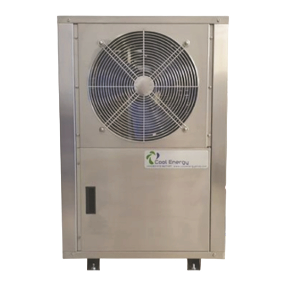
- Page 1 Cool Energy Monoblock Inverter Series Heat Pump Water Heaters Version 2.1 Installation and Users Guide IMPORTANT SAFETY INSTRUCTIONS READ AND FOLLOW ALL INSTRUCTIONS RETAIN THIS GUIDE FOR FUTURE REFERENCE P a g e...
- Page 2 Cool Energy Inverter Series Installation and User Guide Customer Service If you have any questions about ordering Air Source Heat Pump replacement parts and products, please get in touch. Customer Service and Technical Support (Open from 9am-4pm Monday- Friday) Phone: 01472 867497 Email: sales@coolenergyshop.com...
-
Page 3: Table Of Contents
Table of Contents IMPORTANT SAFETY PRECAUTIONS....................5 Health and Safety (Materials)....................5 Important End User Safety Information................... 6 Section 1........................... 7 Introduction........................... 7 Product Overview........................7 General Features........................7 Section 2........................... 8 Installation............................. 8 Materials needed for installation....................8 Specification tables for Units....................8, 9 Installation of Outdoor Unit.................... - Page 4 Section 3......................... 20 Operating Heat Pump........................20 LCD User-Friendly Interface Controller................... 20 General Instruction......................... 20 Controller Panel........................21 Controller Set-up........................21 1. Temperature Setting......................21 2. System Status Display Value.................... 21 3. Clock Setting........................22 4. Timer Setting........................23 5. Manual/Forced Defrosting....................24 General Operating Guide........................
-
Page 5: Health And Safety (Materials)
Under the Consumer Protection Act 1987 and the Health and Safety at Work Act 1974, it is required to provide information on substances hazardous to health (COSHH Regulations 1998). Cool Energy takes every reasonable care to ensure that these products are designed and constructed to meet these general safety requirements, provided they are properly installed and used. - Page 6 IMPORTANT SAFETY INFORMATION FOR THE END-USER • Installation of the appliance must only be carried out by persons with suitable competence. • Do not attempt to modify, repair or service the appliance yourself. • Do not insert body parts or any other items into the air inlet or outlet. •...
-
Page 7: Section 1
Air Source Heat Pumps transfer heat from the ambient air to water, providing high-temperature hot water up to 60°C. The unique Cool Energy heat hump is widely used for house heating or hot water. With our innovative & advanced technology, the pro mono block range of heat pumps can operate very well down to -15°C ambient temperature with high output temperatures up to 60°C. -
Page 8: Section 2
Section 2 Installation The following general information describes how to install the air source heat pump. Note: Before installing this product, read and follow all warning notices and instructions. Only a qualified / competent person should install the heat pump. Materials needed for Installation: The following items are needed and are to be supplied by the installer for all heat pump installations:... - Page 9 Note: The above design and specifications are subject to change without prior notice for product improvement. For detailed specifications of the units please refer to name plate on the units. Correct installation is required to ensure safe operation. The requirements for Cool Energy heat pumps include the following: 1.
-
Page 10: Installation Of Outdoor Unit
Installation of Outdoor Unit The heat pump should be installed on a solid level base that can take the weight, preferably a concrete foundation. If concrete slabs are used, they must rest on asphalt or shingle. The heat pump should not be positioned next to sensitive walls, for example, next to a bedroom. Also ensure that the placement does not inconvenience the neighbours. - Page 11 The installation space should be referred as follows: Intake and outlet should not be obstructed. The wall the unit is to be mounted on should be strong enough to bear the weight and vibrations of the unit. Allow for proper clearances around the unit. Location should allow easy access for maintenance. For any further guidance on heat pump installations for planning purposes, please consult the latest version of the MCS guidelines or your local authority.
-
Page 12: Suggested Installation Methods 12
Suggested Installation Method 1: - Heating with Hot Water Priority- Buffer 12 | P a g e... - Page 13 Suggested Installation Method 2: - Hot Water / Buffer / Thermal Store Only 13 | P a g e...
- Page 14 Suggested Installation Method 3: - Heating Only with Buffer 14 | P a g e...
-
Page 15: Water Connections
Water Connections Water connections at the heat pump Flexible pipe fittings are recommended to be installed on the flow and return connections. (Figure 5) The water inlet and outlet connections to the heat pump, accept standard BSP threaded fittings. CAUTION –... -
Page 16: Electrical Connections
Electrical Connections WARNING – Risk of electrical shock or electrocution. Ensure that all high voltage circuits are disconnected before commencing heat pump installation. Contact with these circuits could result in death or serious injury to users, installers or others. CAUTION – Label all wires prior to disconnection when servicing the heat pump. Wiring errors can cause improper and dangerous operation. - Page 17 Wiring Diagram CE-iH6-18 17 | P a g e...
-
Page 18: Power Supply
Power Supply 1. If the supply voltage is too low or too high, it can cause damage and/or result in unstable operation of the heat pump unit, due to high in rush currents on start up. 2. The minimum starting voltage should be above 90% of rated voltage. The acceptable operating voltage range should be within ±10% of the rated voltage. -
Page 19: Section 3
Section 3 Operating Your Heat Pump LCD User-Friendly Interface Controller General Instructions The operation panel features: 1. Capacitive touch keys for higher operating sensitivity and unlimited key operations. 2. Minimal electromagnetic susceptibility and interference. 3. Stylish appearance of easy viewing purposes. 4. -
Page 20: Controller Set-Up
Keys Explanation: Unlocking Keys: Press the key for 3 seconds until you hear the audible tone, then release the key. The backlight of the LCD display will turn on and the key pad is locked with no “lock key display” symbol . - Page 21 Not Used 40℃ Not Used 10℃ Restart temperature difference 3℃─15℃ 5℃ 3℃ Not Used 0℃─6℃ Displayed temperature difference Electric Heating (Hybrid Function) 0 – On / 1 - 0 - Auto Defrosting Mode 0 / 1 Defrost Mode Enter Temp -15℃─2℃...
-
Page 22: Clock Setting
d13. Protection code d14. Closing code d15. Closing time(the last time closing,min) d16. Outdoor motor fan speed d17. Target frequency d18. EVI EEV opening(display real opening) d19. IPM module temperature d20. WIFI connection status:0 no connection,3 connecting AP,4 connected AP,5 connected to cloud service 3. -
Page 23: General Operating Guide
Press the “ ” key for more than 8 seconds until an audible tone is heard, and release key. The heat pump will be in defrosting mode and the “defrost” symbol will be on display. General Operating Guide Initial Start-Up Precautions First boot-strap and running state checks. -
Page 24: Product Protection
f. To avoid electric shock or fire, don’t store or use, oil paint, petrol, combustible gas or liquid around the unit; don’t throw water or other liquid on to the unit and don’t touch the unit with wet hands. g. Don’t adjust the switch, valve, controller or internal data without permission of customer support team. - Page 25 If there is a water tank temperature probe fault and then ambient temp decides to go into anti-freeze mode, it will only trigger mode 1. If there is an ambient temperature probe fault, then the unit automatically goes into mode 1 anti-freeze protection.
-
Page 26: Section 4
Section 4 General maintenance Controller Error Codes The following Common Error Codes for the heat pump units displayed on the controller: CODE NAME CODE NAME Er01 PCB / Wire Controller Fault Er19 Return air probe fault Er02 Water Tank Probe Fault Er20 Throttled temperature probe fault Er03... -
Page 27: Inspection And Service
Inspection and Service Cool Energy air source heat pumps are designed and built to provide long life and performance, when installed and operated properly under normal conditions. Periodic inspections are important to keep your heat pump running safely and efficiently. - Page 28 • Keep your hands and hair clear of the fan blades to avoid injury. • DO NOT attempt to adjust or service the unit without consulting your authorized installer/agent. • PLEASE read the complete Installation and/or User’s Guide before attempting to operate service or adjust the heater.
- Page 29 Cool Energy Holding Ltd. 169-177 Cleethorpe Road, Grimsby, DN31 3AX. Email: sales@coolenergyshop.com www.coolenergyshop.com 29 | P a g e...
Need help?
Do you have a question about the Monoblock Inverter Series and is the answer not in the manual?
Questions and answers