Table of Contents
Advertisement
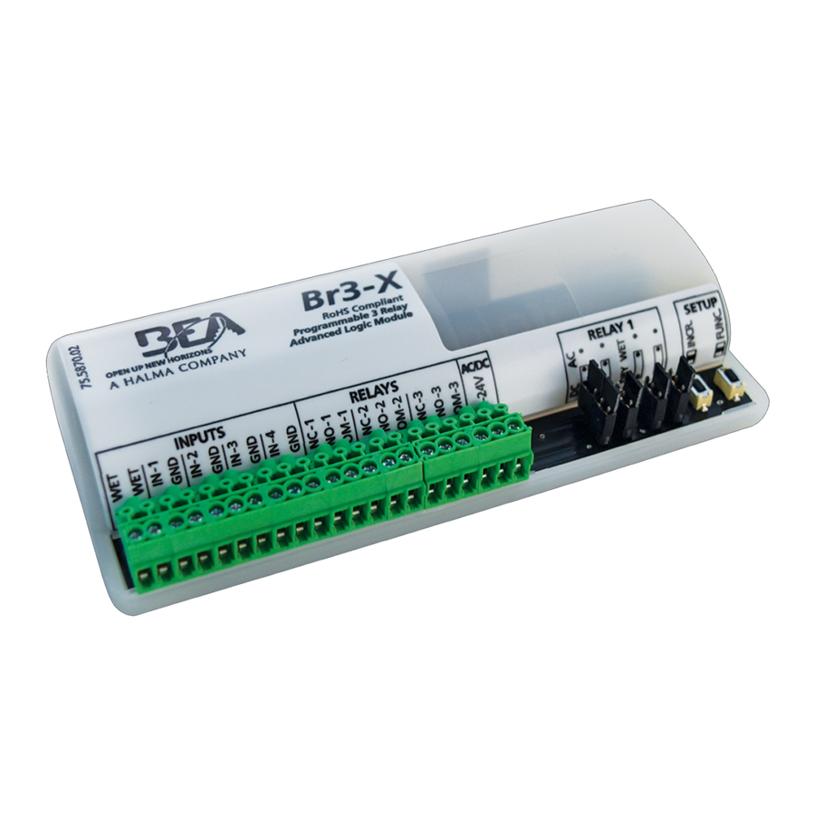
DESCRIPTION
1
2
1. WET input
2. DRY inputs
ACCESSORIES
10RESTROOMKIT: Restroom Control Kit
COMPONENT
Logic module
Door position switch
Occupied indicator
"PUSH TO LOCK" button
10EMERGENCYKIT: Emergency Add-On Kit
Assistance Required signal
"PUSH FOR EMERGENCY ASSISTANCE" button
75.5871.04 BR3-X 20180702
75.5871.04 BR3-X 20180702
3
4
3. Relay outputs
4. Power input
NO/NC magnetic door position switch
lock status indicator with LED and sounder
COMPONENT
Emergency signage
Programmable, 3-Relay, Advanced
Logic Module & Restroom Controller
8
5
6
5. AC/DC jumpers
6. WET/DRY jumpers
DESCRIPTION
Br3-X restroom controller
door lock actuator with LED
DESCRIPTION
corridor LED with sounder
emergency instruction signage
emergency assistance request
button with LED and sounder
BR3-X
(US version)
7
7. Programming buttons
8. 7-segment display
PART NUMBER
10BR3X
10SWITCH1084
10LEDSOUNDER
10PTLBUTTON
PART NUMBER
10ARS
70.5675
10BUTTONCOMBO
Page 1 of 12
Page 1 of 12
Advertisement
Table of Contents

Related Manuals for BEA Br3x


Summary of Contents for BEA Br3x
- Page 1 BR3-X Programmable, 3-Relay, Advanced Logic Module & Restroom Controller (US version) DESCRIPTION 1. WET input 3. Relay outputs 5. AC/DC jumpers 7. Programming buttons 2. DRY inputs 4. Power input 6. WET/DRY jumpers 8. 7-segment display ACCESSORIES 10RESTROOMKIT: Restroom Control Kit COMPONENT DESCRIPTION PART NUMBER...
- Page 2 DO NOT attempt any internal repair of the components. All repairs and/or component replacements must be performed by BEA, Inc. Unauthorized disassembly or repair: 1. May jeopardize personal safety and may expose one to the risk of electrical shock.
- Page 3 WIRING Each Br3-X function is wired differently. Please review and follow the appropriate wiring diagram shown for each function. FUNCTIONS FUNCTION DESCRIPTION LOGIC • activation of relay 1 via trigger of input 1 timer • reverse logic available ratchet / latching •...
- Page 4 PROGRAMMING Press and hold INCR + FUNC Display will toggle between While FF / 00 is displayed, for 3 seconds. FF and 00 for 5 seconds. press INCR to cycle through functions. Once desired function is Display will toggle between Press INCR to cycle through selected, press FUNC to cycle...
- Page 5 PROGRAMMING PARAMETERS * see page 3 for specific parameter details * 10 – timer AVAILABLE PARAMETERS: h1 - relay 1 hold time rL - reverse logic 1. Trigger INPUT 1. • RELAY 1 will close and hold for time h1. FUNCTION 10 NOTE: Reverse logic allows for a Normally Closed (NC) INPUT 1.
- Page 6 PROGRAMMING PARAMETERS (cont) 28 – 2-relay sequencer + door position AVAILABLE PARAMETERS: h1 - relay 1 hold time h2 - relay 2 hold time d1 - delay between relays 1 & 2 h1 must be greater than d1 when using an electric lock 1.
- Page 7 PROGRAMMING PARAMETERS (cont) 36 – 3-relay sequencer + ‘1-shot’ AVAILABLE PARAMETERS: h1 - relay 1 hold time h2 - relay 2 hold time h3 - relay 3 hold time d1 - delay between relays 1 & 2 d2 - delay between relays 1 & 3 h1 must be greater than d1 when using an electric lock 1.
- Page 8 PROGRAMMING PARAMETERS (cont) 50 – interlock timer AVAILABLE PARAMETERS: h1 - relay 1 hold time h2 - relay 2 hold time 1. Trigger INPUT 1. • RELAY 1 will close and hold for time h1. 2. Trigger INPUT 2. • RELAY 2 will close and hold for time h2.
- Page 9 PROGRAMMING PARAMETERS (cont) 65 – 2-way 2-relay sequence AVAILABLE PARAMETERS: h1 - relay 1 hold time h2 - relay 2 hold time d1 - delay between relays 1 & 2 d2 - delay between relays 2 & 1 1. Trigger INPUT 1. •...
- Page 10 PROGRAMMING PARAMETERS (cont) nU – normally unlocked restroom AVAILABLE PARAMETERS: h2 - relay 2 hold time d1 - delay between relays 1 & 2 1. Trigger INPUT 1. • RELAY 2 will close and hold for time h2. 2. Trigger INPUT 3. •...
- Page 11 TEST Upon completion of jumper settings, wiring, and programming, test the Br3-X to ensure all function parameters are working correctly and as intended for the specific application. RELAY STATUS STATUS DESCRIPTION relay 1 closed when wired NO or open when wired NC relay 2 closed when wired NO or open when wired NC relay 3 closed when wired NO or open when wired NC relay 1 and relay 2 closed when wired NO or open when wired NC...
- Page 12 BEA strongly recommends that installation and service technicians be AAADM-certifi ed for pedestrian doors, IDA-certifi ed for doors/gates, and factory- trained for the type of door/gate system.
Need help?
Do you have a question about the Br3x and is the answer not in the manual?
Questions and answers