Autonics CT Series User Manual
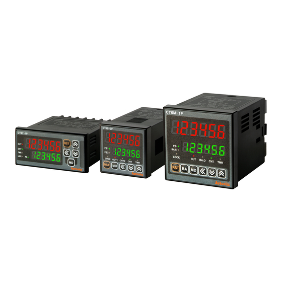
Programmable counter/timer
Hide thumbs
Also See for CT Series:
- Manual (13 pages) ,
- Product manual (11 pages) ,
- User manual (85 pages)
Table of Contents
Advertisement
Quick Links
Advertisement
Table of Contents

Related Manuals for Autonics CT Series


Summary of Contents for Autonics CT Series
- Page 1 Programmable Counter/Timer CT Series USER MANUAL For COMMUNICATION CT Series...
- Page 2 © Copyright Reserved Autonics Co., Ltd.
- Page 3 Preface Preface Thank you for purchasing an Autonics product. Please familiarize yourself with the information contained in the Safety Precautions section before using this product. This user manual contains information about the product and its proper use, and should be kept in a place where it will be easy to access.
-
Page 4: User Manual Guide
Visit our web site (www.autonics.com) to download a copy. The manual's content may vary depending on changes to the product's software and other unforeseen developments within Autonics, and is subject to change without prior notice. Upgrade notice is provided through out homepage. ... -
Page 5: Communication Protocol
Communication Protocol Communication Protocol CT Series is accepted to Modbus RTU Protocol. Users should be aware that it does not support a broadcast command. © Copyright Reserved Autonics Co., Ltd. -
Page 6: User Manual Symbols
Failure to follow instructions can result in serious injury or death. Failure to follow instructions can lead to a minor injury or product damage. An example of the concerned feature's use. ※1 Annotation mark. © Copyright Reserved Autonics Co., Ltd. -
Page 7: Safety Precautions
Failure to follow this instruction may result in electric shock or fire. Do not use the unit where flammable or explosive gas, humidity, direct sunlight, radiant heat, vibration, or impact may be present. Failure to follow this instruction may result in fire or explosion. © Copyright Reserved Autonics Co., Ltd. - Page 8 Keep dust and wire residue from flowing into the unit. Failure to follow this instruction may result in fire or product damage. The specifications of communication manual are subject to change and some models may be discontinued without notice. viii © Copyright Reserved Autonics Co., Ltd.
-
Page 9: Table Of Contents
2.3 Product Information ....................... 20 2.4 Monitoring data ......................21 2.5 Preset value setting group ..................... 22 2.6 Function setting mode ....................23 Counter group ................... 23 2.6.1 Timer group ....................24 2.6.2 Communication group ................25 2.6.3 © Copyright Reserved Autonics Co., Ltd. - Page 10 Table of Contents © Copyright Reserved Autonics Co., Ltd.
-
Page 11: Modbus Rtu Protocol
Response (Slave) Data Data Error check (CRC16) Slave address Function Byte count (000008 to (000010 to High 000001) 000009) 11 H 01 H 02 H CD H 01 H ## H ## H © Copyright Reserved Autonics Co., Ltd. -
Page 12: Read Input Status(Func 02-02H)
Response (Slave) Data Data Error check (CRC16) Slave address Function Byte count (100008 to (100010 to High 100001) 100009) 11 H 02 H 02 H CD H 01 H ## H ## H © Copyright Reserved Autonics Co., Ltd. -
Page 13: Read Holding Registers(Func 03-03H)
Response (Slave) Data Data Error check (CRC16) Slave address Function Byte count High High High 11 H 03 H 04 H 02 H 2B H 00 H 64 H ## H ## H © Copyright Reserved Autonics Co., Ltd. -
Page 14: Read Input Registers(Func 04-04H)
Response (Slave) Data Data Error check (CRC16) Slave address Function Byte count High Low High High 11 H 04 H 04 H 00 H 0A H 00 H 14 H ## H ## H © Copyright Reserved Autonics Co., Ltd. -
Page 15: Force Single Coil(Func 05-05H)
## H Response (Slave) Starting address Preset data Error check (CRC16) Slave address Function High High High 11 H 05 H 00 H 00 H FF H 00 H ## H ## H © Copyright Reserved Autonics Co., Ltd. -
Page 16: Preset Single Registers(Func 06-06H)
## H Response (Slave) Starting address Preset data Error check (CRC16) Slave address Function High High High 11 H 06 H 00 H 00 H 00 H 0A H ## H ## H © Copyright Reserved Autonics Co., Ltd. -
Page 17: Preset Multiple Registers(Func 16-10H)
(device) connecting with external devices such as PLC, Graphic Panel, except in the case of download that presets the minimum/maximum or basic value of parameter by Input specifications in PC Loader Program © Copyright Reserved Autonics Co., Ltd. -
Page 18: Exception Response-Error Code
E8 H 00 H 01 H ## H ## H Response (Slave) Error check (CRC16) Function Slave address Exception Code +80 H High 11 H 81 H 02 H ## H ## H © Copyright Reserved Autonics Co., Ltd. -
Page 19: Modbus Mapping Table
0: OFF 1: ON 100003 (0002) INHIBIT input status Terminal input status 0: OFF 1: ON 100004 (0003) RESET input status Terminal input status 0: OFF 1: ON 100005 (0004) BATCH RESET input status Terminal input status © Copyright Reserved Autonics Co., Ltd. -
Page 20: Product Information
Input Status Start Address 0000 300121 (0078) Input Status Quanity 300122 (0079) Holding Register Start Address 0000 300123 (007A) Holding Register Quantity 300124 (007B) Input Register Start Address 0064 300125 (007C) Input Register Quantity © Copyright Reserved Autonics Co., Ltd. -
Page 21: Monitoring Data
4-digit type: -999 to 9999 310010 (03F1) Timer: within time setting range 310011 (03F2) Setting value of BATCH 0 to 999999 counter 310012 (03F3) 0: NPN 1: PNP 310013 (03F4) Checking the input logic © Copyright Reserved Autonics Co., Ltd. -
Page 22: Preset Value Setting Group
4-digit type: 0 to 9999 400003 (0002) Use counter and Timer: within time setting range 03/06/16 PRESET1 setting value timer in common 400004 (0003) 400005 (0004) BATCH counter setting 0 to 999999 03/06/16 value 400006 (0005) © Copyright Reserved Autonics Co., Ltd. -
Page 23: Function Setting Mode
4-digit type: 0000 to 9999 400064 (003F) value Memory 0: CLR 1: REC protection 400065 (0040) Use counter and [DATA] 03/06/16 timer in common 0: lOFF 2: LOc2 400066 (0041) Lock key [LOCK] 1: LOc1 3: LOc3 © Copyright Reserved Autonics Co., Ltd. -
Page 24: Timer Group
[DATA] and timer in common 0: lOFF 2: LOc2 Lock key 400109 (006C) 03/06/16 1: LOc1 3: LOc3 [LOCK] Indication For the 0: TOTAL 1: HOLD 2: ONtD 400110 (006D) 03/06/16 mode [DSpM] indicator © Copyright Reserved Autonics Co., Ltd. -
Page 25: Communication Group
Comm. parity bit [PRTY] 0: 1 1: 2 400154 (0099) 03/06/16 Comm. stop bit [STP] 400155 (009A) 03/06/16 Response waiting time [RSwT] 05 to 99 Unit: ms 0: ENA 1: DISA 400156 (009B) 03/06/16 Comm. writing [COmW] © Copyright Reserved Autonics Co., Ltd. - Page 26 #402-303, Bucheon Techno Park, 655, Pyeongcheon-ro, Wonmi-gu, Bucheon, Gyeonggi-do, South Korea 14502 Tel: 82-32-610-2730 / Fax: 82-32-329-0728 / E-mail: sales@autonics.com ■ Brazil − Autonics do Brasil Comercial Importadora Exportadora Ltda Tel: 55-11-2307-8480 / Fax: 55-11-2309-7784 / E-mail: comercial@autonics.com.br ■ China − Autonics electronic(Jiaxing) Corporation Tel: 86-21-5422-5969 / Fax: 86-21-5422-5961 / E-mail: china@autonics.com...
Need help?
Do you have a question about the CT Series and is the answer not in the manual?
Questions and answers