Table of Contents
Advertisement
Available languages
Available languages
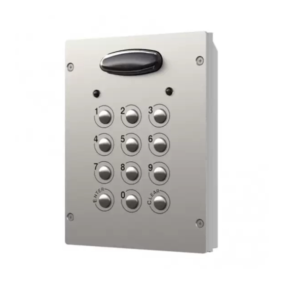
8000 Series
Art. 8800 - Art. 8800-3
Fig. 1
GENERAL DIRECTIONS FOR INSTALLATION
In order to achieve the best results from the schematics described it is necessary to install only original VIDEX equipment, strictly
keeping to the items indicated on each schematic and follow these General Directions for Installation:
• The system must be installed according to national rules in force, in any case the running of cables of any intercom unit must be
carried out separately from the mains;
• All multipair cables should be compliant to CW1308 specification (0.5mm twisted pair telephone cable.
» Cables for speech line and service should have a max resistance of 10Ω
» Lock release wires should be doubled up (Lock release wires and power supply wires should have a max resistance of 3Ω);
• The cable sizes above can be used for distances up to 50m. On distances above 50m the cable sizes should be increased to keep
the overall resistance of the cable below the RESISTANCES indicated above;
• Double check the connections before power up;
• Power up the system then check all functions.
LOCK RELEASE BACK EMF PROTECTION
A varistor must be fi tted across the terminals on AC lock release (Fig.1A) and a diode must be fi tted across the terminals on a DC
lock release (Fig.1B) to suppress back EMF voltages. Connect the components to the lock releases as shown in fi gures.
Fig. 1A
Art. 8800 - Installation instructions
Digital codelock module
VARISTOR (MOV)
12V AC
LOCK RELEASE
DESCRIPTION
Access control system with 2 codes and 2 Relay outputs for
Art. 8800 (3 codes and 3 Relay outputs for Art. 8800-3).
• Engineer's code to enter into the "Programming Menu" ( from
4 to 8 digits).
• Programming of the activation time of each relay from 1 up to
99 seconds or latching.
• Possibility to activate relay 1 by shorting terminal SW1 to GND
and relay 2 by shorting terminal SW2 to GND. Both relays will
operate for the programmed time.
• Keypad gives an acoustic (buzzer) signal during the entering
of codes and a continuous melody for 4 or more seconds, ac-
cording to the number of mistakes (self protection).
• Keypad includes panel illumination and 2 LED's to show the
following:
» Correct relay code (green LED on for 2 seconds).
» Red LED to indicate when in the "programming menu".
AVAILABLE VERSIONS
Art. 8800:
Module 2 Relay with keypad illumination LEDs
Art. 8800-3: Module 3 Relay with keypad illumination LEDs
Fig. 1B
- 1 -
DIODE
1N4002
12V DC
LOCK RELEASE
65801280 - V2.0 - 30/06/18
Advertisement
Table of Contents

Related Manuals for Videx 8800


Summary of Contents for Videx 8800
- Page 1 GENERAL DIRECTIONS FOR INSTALLATION In order to achieve the best results from the schematics described it is necessary to install only original VIDEX equipment, strictly keeping to the items indicated on each schematic and follow these General Directions for Installation: •...
- Page 2 Art. 8800-3) or re-enter the existing code then press Press Enter ENTER (Melody). (melody) • Enter the RELAY 3 (only for Art. 8800-3) operation time (2 dig- Two digits (01 to 99) ENTER its 01 to 99 I.E. 05=5 seconds, 00=remain open time) or re-en- i.E.
- Page 3 ** On the first loop of the flow chart its relay 1, second loop is and relay 3 relay 2 and third loop is relay 3. PRESS ENTER *** Only for Art. 8800-3 TWICE TO EXIT PROGRAMMING ART. 8800 CONNECTION TERMINALS SIGNALS ART. 8800-3 CONNECTION TERMINALS SIGNALS...
- Page 4 Art. 8800-3: Modulo a 3 Relè con illuminazione tastiera NORME GENERALI D’INSTALLAZIONE Per eseguire una corretta installazione è necessario impiegare esclusivamente parti VIDEX, seguire con scrupolo quanto indicato negli schemi di collegamento e tenere presenti le norme generali d’installazione: • Realizzare gli impianti secondo le vigenti normative nazionali ed in ogni caso si •...
- Page 5 • Se viene digitato un codice errato, l’unità si blocca per 5 secondi: il tempo di blocco aumenta in base al numero di errati inseri- menti. L’unità funzionerà solo digitando un codice corretto. - 5 - Art. 8800 - 8800-3 - Istruzioni di installazione 65801280 - V2.0 - 30/06/18...
- Page 6 82mA 21.5mA • prodotti abrasivi; In funzione: 125mA 35.0mA • prodotti contenenti cloro; Working Temperature: -10 +50° C • prodotti per la pulizia dei metalli. - 6 - Art. 8800 - 8800-3 - Istruzioni di installazione 65801280 - V2.0 - 30/06/18...
- Page 7 Art. 8800-3 : Module à 3 Relais avec éclairage clavier NORMES GÉNÉRALES D’INSTALLATION Pour effectuer une installation correcte il faut utiliser exclusivement des pièces VIDEX, suivre attentivement ce qui est indiqué sur les schémas de raccordement et respecter les normes générales d’installation : •...
- Page 8 • Si un code erroné est saisi, l’unité se bloque pendant 5 secondes : le temps de blocage augmente en fonction du nombre de sai- sies erronées. L’unité fonctionnera uniquement en saisissant un code correct. - 8 - Art. 8800 - 8800-3 - Manuel d'installation 65801280 - V2.0 - 30/06/18...
- Page 9 82mA 21.5mA • liquids abrasifs ; En fonction : 125mA 35.0mA • liquids avec chlore ; Working Temperature : -10 +50 °C • nettoyants pour surfaces metalliques. - 9 - Art. 8800 - 8800-3 - Manuel d'installation 65801280 - V2.0 - 30/06/18...
- Page 10 FAIL SAFE DC LOCK ART.521 1N4002 12Vdc 230V PUSH TO EXIT FAIL SAFE LOCK RELEASE 12Vdc P.S.U. 12¸ 24 VX8800 Vac/dc FAIL SECURE AC LOCK 100uF 12Vac PUSH TO EXIT FAIL SECURE LOCK RELEASE 12Vac P.S.U. 12¸ 24 VX8800 Vac/dc ART.321 230V ELECTRIC GATES...
- Page 11 Art.3111 n....Art.8845.. 4 6 2 Art.8837M-2.. ART.520M 230V 0 +12 + C2 NO2 12¸ 24 VX8800 Vac/dc VX8800-8837M.dwg - 11 - 65801280 - V2.0 - 30/06/18...
- Page 12 - 12 - 65801280 - V2.0 - 30/06/18...
- Page 13 Art.3111 n....Art.8845.. 4 6 2 Art.8837M-2.. ART.520M 230V 0 +12 + C2 NO2 12¸ 24 VX8800 Vac/dc VX8800-8837M.dwg - 13 - 65801280 - V2.0 - 30/06/18...
- Page 14 POWER 24Vac/dc 5A max FUSE - 14 - 65801280 - V2.0 - 30/06/18...
- Page 15 - 15 - 65801280 - V2.0 - 30/06/18...
- Page 16 MANUFACTURER VIDEX ELECTRONICS S.P.A. FABBRICANTE Via del Lavoro, 1 FABRICANT 63846 Monte Giberto (FM) Italy FABRICANTE Tel (+39) 0734 631669 FABRIKANT Fax (+39) 0734 632475 www.videx.it - info@videx.it CUSTOMER SUPPORT VIDEX ELECTRONICS S.P.A. UK Customers only: SUPPORTO CLIENTI VIDEX SECURITY LTD www.videx.it - technical@videx.it...
Need help?
Do you have a question about the 8800 and is the answer not in the manual?
Questions and answers