
Related Manuals for WAGNER ProfiTech M


Summary of Contents for WAGNER ProfiTech M
- Page 1 Translation of the Original Operating Manual Hardware + Installation Profi Tech M Version 07 / 2014 II 3D Ex tc IIIB T60°C Dc...
-
Page 3: Table Of Contents
Safety Instructions for the Operator 4.1.1 Electrical Devices and Equipment 4.1.2 Staff Qualifi cations 4.1.3 Safe Work Environment Safety Instructions for Staff 4.2.1 Safe Handling of WAGNER Powder Spray Devices 4.2.2 Grounding the Device 4.2.3 Product Hoses 4.2.4 Cleaning 4.2.5 Handling Powder Lacquers... - Page 4 ProfiTech M VERSION 07/2014 ORDER NUMBER DOC 2335144 OPERATING MANUAL Table of Contents 6.11 Miscellaneous 6.12 Technical Data 6.12.1 MCM Master Control 6.12.2 MCM CPS I/O Control 6.12.3 Technical Data for Maximum Profi Tech M Confi guration 6.12.4 Rack (10 EPG S2) 6.12.5 EPG S2...
- Page 5 ProfiTech M VERSION 07/2014 ORDER NUMBER DOC 2335144 OPERATING MANUAL Table of Contents 7.15.4 Setting Node ID and Baud Rate on Reciprocator 7.15.5 Connecting Spray Gun Blow Out Fixture 7.16 Grounding 7.17 Commissioning OPERATION Training the Operating Staff Safety Instructions Work 8.3.1...
-
Page 6: General
ProfiTech M VERSION 07/2014 ORDER NUMBER DOC 2335144 OPERATING MANUAL GENERAL PREFACE The operating manual contains information about safely operating, maintaining, cleaning and repairing the device. The operating manual is part of the device and must be available to operating and service staff . -
Page 7: Languages
ProfiTech M VERSION 07/2014 ORDER NUMBER DOC 2335144 OPERATING MANUAL This operating manual describes the components and installation of a Profi Tech M system (control cabinet, electrical connections and preparation for fi rst commissioning). This operating manual is to be used alongside the Profi Tech M "System Operation"... -
Page 8: Terminology For The Purpose Of This Manual
ProfiTech M VERSION 07/2014 ORDER NUMBER DOC 2335144 OPERATING MANUAL TERMINOLOGY FOR THE PURPOSE OF THIS MANUAL Cleaning Manual cleaning of devices and device parts with cleaning agent Flush Internal fl ushing with compressed air of parts carrying paint Staff qualifi cations... -
Page 9: Correct Use
SAFETY PARAMETERS WAGNER accepts no liability for any damage arising from non-intended use. Use the device only to work with the products recommended by WAGNER. Operate only the device as a whole. Do not deactivate safety fi xtures. -
Page 10: Processible Working Materials
ProfiTech M VERSION 07/2014 ORDER NUMBER DOC 2335144 OPERATING MANUAL PROCESSIBLE WORKING MATERIALS Types of powder which can be charged electrostatically Metallic powder REASONABLY FORESEEABLE MISUSE The forms of misuse listed below may result in physical injury or property damage: Coating work pieces which are not grounded;... -
Page 11: Identification
ProfiTech M VERSION 07/2014 ORDER NUMBER DOC 2335144 OPERATING MANUAL IDENTIFICATION EXPLOSION PROTECTION IDENTIFICATION The device is suitable for use in potentially explosive areas (Zone 22). All connections and cable entries not needed must therefore be sealed. 3.1.1 MCM MASTER CONTROL... -
Page 12: Type Plate
ProfiTech M VERSION 07/2014 ORDER NUMBER DOC 2335144 OPERATING MANUAL TYPE PLATE J. Wagner AG J. Wagner AG CH 9450 Altstätten Made in Switzlerland CH 9450 Altstätten Made in Switzerland II 3D II 3D Ex tc IIIB T60ºC Dc Ex tc IIIB T60ºC Dc... -
Page 13: General Safety Instructions
ProfiTech M VERSION 07/2014 ORDER NUMBER DOC 2335144 OPERATING MANUAL GENERAL SAFETY INSTRUCTIONS SAFETY INSTRUCTIONS FOR THE OPERATOR Keep this operating manual at hand near the device at all times. Always follow local regulations concerning occupational safety and accident prevention. -
Page 14: Safety Instructions For Staff
4.2.1 SAFE HANDLING OF WAGNER POWDER SPRAY DEVICES Do not point spray guns at people. Before all work on the device, in the event of work interruptions and functional faults: - Switch off the energy/compressed air supply. -
Page 15: Cleaning
ProfiTech M VERSION 07/2014 ORDER NUMBER DOC 2335144 OPERATING MANUAL 4.2.4 CLEANING Before starting cleaning or any other manual work, the high-voltage in the spray area must be shut down and locked to prevent it from being switched back on. -
Page 16: Safety Feature Identification
ProfiTech M VERSION 07/2014 ORDER NUMBER DOC 2335144 OPERATING MANUAL SAFETY FEATURE IDENTIFICATION Plates bearing information for the user have been attached to the work openings of the powder coating booth. The plate size corresponds to the standard category Ø 100 mm; 3.94 inches. -
Page 17: Disclaimer
HARDWARE Any amendments by the user or any third party to the structure of the control cabinet delivered by J. WAGNER GmbH, in particular in respect of the electric controller, require the written permission of J. WAGNER GmbH. Any amendments, which were not permitted, immediately lead to the exclusion of all warranty, liability and guarantee claims by the manufacturer. -
Page 18: Component Description
ProfiTech M VERSION 07/2014 ORDER NUMBER DOC 2335144 OPERATING MANUAL COMPONENT DESCRIPTION FUNCTIONAL DESCRIPTION The Profi Tech M controller is used in automatic coating systems. The controller controls: Powder output quantity Powder atomization High-voltage Current limitation Motion technology Gap control... -
Page 19: Mcm Controller Components
ProfiTech M VERSION 07/2014 ORDER NUMBER DOC 2335144 OPERATING MANUAL MCM CONTROLLER COMPONENTS MCM Master Control Module: Order No. 2330000 The MCM Master Control Module serves as an operating unit and as a controller MCM CPS I/O Control Module: Order No. 2330001... - Page 20 ProfiTech M VERSION 07/2014 ORDER NUMBER DOC 2335144 OPERATING MANUAL MCM cable set 10 m; 32.8 ft: Order No. 2330002 Cable set for connection of master module and controller module Consists of: MCM CAN BUS connection cable 10 m Order No. 2330005...
- Page 21 ProfiTech M VERSION 07/2014 ORDER NUMBER DOC 2335144 OPERATING MANUAL CAN bus termination Order No. 2321402 for EPG S2 and external extension P_02192 CAN bus termination Order No. 2338042 for light curtain and motion technology P_02193...
-
Page 22: Control Unit/Spray Gun Components
ProfiTech M VERSION 07/2014 ORDER NUMBER DOC 2335144 OPERATING MANUAL CONTROL UNIT/SPRAY GUN COMPONENTS Rack: Order No. 2328670 The rack includes: Air distributor complete 10 x 1" Order No. 2326124 Hose 5.5/8 mm, 10 m Order No. 9982078 Base rack for a maximum of 10 EPG S2 control units The main air valve must be controlled with the MCM in order to achieve the interlock with the main air monitoring. - Page 23 ProfiTech M VERSION 07/2014 ORDER NUMBER DOC 2335144 OPERATING MANUAL Shelf (base): Order No. 2328668 Blanking plate: Order No. 2328669 To close free spaces when the frame is not fully fi tted. Connection set EPG S2: Order No. 2321529 CAN bus cable 0.6 m; 1.97 ft Order No.
- Page 24 ProfiTech M VERSION 07/2014 ORDER NUMBER DOC 2335144 OPERATING MANUAL Sprint connection cable The connection cable is required to connecting the EPG-Sprint X control unit. Connection cable 10 m; 32.8 ft Order No. 2335605 P_02189 Terminating resistor Order No. 2321402...
-
Page 25: Pulse Generator Components
ProfiTech M VERSION 07/2014 ORDER NUMBER DOC 2335144 OPERATING MANUAL PULSE GENERATOR COMPONENTS Encoder Order No. 2335582 Hollow shaft encoder 24V/100 pulses P_01957 Bracket set for encoder Order No. 2335512 P_02188 Connection cable for encoder Order No. 2336565 Connection cable, tailored 30 m... -
Page 26: Light Grid Set Lgs 25 Components
ProfiTech M VERSION 07/2014 ORDER NUMBER DOC 2335144 OPERATING MANUAL LIGHT GRID SET LGS 25 COMPONENTS Light grid set LGS 25, 300 mm Order No. 2330170 Consists of: Light grid LGS 25 300 mm, switching output Mounting support Connection cable transmitter 25 m; 4 x 0.34 Connection cable receiver 20 m;... - Page 27 ProfiTech M VERSION 07/2014 ORDER NUMBER DOC 2335144 OPERATING MANUAL Quattro CAN open control unit for light curtain Order No. 2330630 Power supply cable to "Kontur 2" light curtain Per meter 3x1.0 mm² Order No. 3052605...
-
Page 28: Light Curtain Cml720I Components (From 06/2014)
ProfiTech M VERSION 07/2014 ORDER NUMBER DOC 2335144 OPERATING MANUAL LIGHT CURTAIN CML720I COMPONENTS (FROM 06/2014) "CML720i" light curtain (resolution 10 / 20 / 40 mm) Module comprising light curtain, transmitter and receiver, 2 brackets, Y cable for supply and Y cable for CAN bus... - Page 29 ProfiTech M VERSION 07/2014 ORDER NUMBER DOC 2335144 OPERATING MANUAL Z holder (2 items) Order No. 2345084 P_02458 24 VDC fi eld distributor and synchronization Order No. 2345972 Field distributor, pre-assembled with 20 m cable The fi eld distributor is needed if 2 - 4 light curtains are used.
-
Page 30: Motion Equipment Components
ProfiTech M VERSION 07/2014 ORDER NUMBER DOC 2335144 OPERATING MANUAL 6.10 MOTION EQUIPMENT COMPONENTS VU1 reciprocator The VU1 reciprocator is suitable for use in automatic powder coating systems with max. 16 spray guns. The number after the designation VU1 indicates the maximum travel in mm. -
Page 31: Miscellaneous
ProfiTech M VERSION 07/2014 ORDER NUMBER DOC 2335144 OPERATING MANUAL 6.11 MISCELLANEOUS Ensure that the following small components pictured are not lost. Small components: For the assembly of the mechanical components and to connect electric cables and the like. System-dependent, consisting of: screws, nuts, connections, end sleeves etc. -
Page 32: Technical Data
ProfiTech M VERSION 07/2014 ORDER NUMBER DOC 2335144 OPERATING MANUAL 6.12 TECHNICAL DATA 6.12.1 MCM MASTER CONTROL Type: Profi Tech M Serial number: see type plate Year of construction: see type plate Supply: 24 VDC / 1 A Power: maximum 17 Watt... -
Page 33: Mcm Cps I/O Control
ProfiTech M VERSION 07/2014 ORDER NUMBER DOC 2335144 OPERATING MANUAL 6.12.2 MCM CPS I/O CONTROL Type: Profi Tech M Serial number: see type plate Year of construction: see type plate Supply: 3L/PEN 230/400 V 50 Hz/60 Hz Power consumption: maximum 5.1 kW... -
Page 34: Technical Data For Maximum Profitech M Configuration
VERSION 07/2014 ORDER NUMBER DOC 2335144 OPERATING MANUAL 6.12.3 TECHNICAL DATA FOR MAXIMUM PROFITECH M CONFIGURATION 4 x HU1 sliding tables, 250W each Sliding table 2 groups with tow units each 4 x VU1 reciprocators, 750W each Reciprocators, 2 groups with two units each 16 EPG-S2 control units, 60W each 16 EPG S2 control units = 32 spray guns (PEA-C2;... -
Page 35: Rack (10 Epg S2)
ProfiTech M VERSION 07/2014 ORDER NUMBER DOC 2335144 OPERATING MANUAL 6.12.4 RACK (10 EPG S2) Dimensions: Width: 500 mm; 19.69 inches Height: 2,200 mm; 86.62 inches Depth: 660 mm; 26 inches Weight: approx. 150 kg; 330.68 lb (if equipped with 10 EPG S2) 6.12.5... -
Page 36: Epg-Sprint X
ProfiTech M VERSION 07/2014 ORDER NUMBER DOC 2335144 OPERATING MANUAL 6.12.6 EPG-SPRINT X Dimensions: Height 136 mm; 5.35 inches Width 270 mm; 10.63 inches Depth (without operating elements) 200 mm; 7.87 inches Weight 3.3 kg; 7.28 lbs Electrical: Mains (AC) 85 VAC –... -
Page 37: Compressed Air Quality
Compressed air quality, accessories Danger of damage to the device. Operate the control unit only with the prescribed compressed air quality. Only use the control unit with original Wagner accessories. Non-observance of these conditions results in the warranty expiring! Ambient conditions: If low-melting powders are used, the ambient temperature may have to be lower than 30 °C;... -
Page 38: Operating Elements On The Master Module
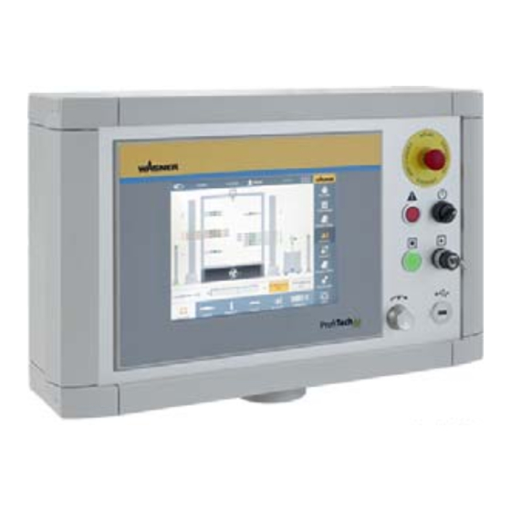
ProfiTech M VERSION 07/2014 ORDER NUMBER DOC 2335144 OPERATING MANUAL 6.14 OPERATING ELEMENTS ON THE MASTER MODULE P_01942 1 PC controller with 10.4" / 26.4 cm screen and touch operation 2 EMERGENCY STOP button System's safety stop button 3 Display "Fault"... -
Page 39: Display Elements Front Side Of Epg S2
ProfiTech M VERSION 07/2014 ORDER NUMBER DOC 2335144 OPERATING MANUAL 6.15 DISPLAY ELEMENTS FRONT SIDE OF EPG S2 EP G P_01487 1 LED display: "Operating Voltage" The LED lights up green when the operating voltage is activated 2 LED display: "CAN Data Communication"... -
Page 40: Assembly And Commissioning
ProfiTech M VERSION 07/2014 ORDER NUMBER DOC 2335144 OPERATING MANUAL ASSEMBLY AND COMMISSIONING TRAINING THE ASSEMBLY STAFF WARNING Incorrect installation/operation! Risk of injury and damage to the device. The assembly staff must have all of the technical skills to safely undertake commissioning. -
Page 41: Assembly Of The Profitech M Components
VERSION 07/2014 ORDER NUMBER DOC 2335144 OPERATING MANUAL ASSEMBLY OF THE PROFITECH M COMPONENTS The following is a typical assembly procedure in described in broad terms. Details regarding installation, connection and commissioning of individual devices are listed in further chapters. -
Page 42: Setting Up The Rack
ProfiTech M VERSION 07/2014 ORDER NUMBER DOC 2335144 OPERATING MANUAL SETTING UP THE RACK WARNING Danger of tipping! Risk of injury and damage to the device. Secure the rack against tipping during transport. Screw rack to base at the fastening holes at the installation site. -
Page 43: System Description
ProfiTech M VERSION 07/2014 ORDER NUMBER DOC 2335144 OPERATING MANUAL SYSTEM DESCRIPTION 7.6.1 CPS CONTROL CABINET DESIGN P_01943 7 8 9 1 Safety fuse for 24 VDC departures at X12 and X30 terminal blocks 2 Multifunctional module MCM I/O unit, Order No. 2330003 3 Universal power supply 220 V±20% / 24 VDC, 5 A for supplying the control system... -
Page 44: Terminal Descriptions
ProfiTech M VERSION 07/2014 ORDER NUMBER DOC 2335144 OPERATING MANUAL 7.6.2 TERMINAL DESCRIPTIONS X10 terminal block for light barriers Function Signal Terminal strip Clamps Contact /Signal type Operating voltage for light barrier +24 VDC +24 VDC fuse FS 1 Light barrier signal... - Page 45 ProfiTech M VERSION 07/2014 ORDER NUMBER DOC 2335144 OPERATING MANUAL X20 terminal block for powder center signal including EMERGENCY STOP Function Signal Terminal strip Clamps Contact /Signal type EMERGENCY STOP from Channel 1 1 and 2 Potential-free NCC Powder Center...
- Page 46 ProfiTech M VERSION 07/2014 ORDER NUMBER DOC 2335144 OPERATING MANUAL X30 terminal block for motion technique and EPG-S2 supply Function Signal Terminal strip Clamps Contact /Signal type Motion group 1 DC+ +24 VDC +24 VDC fuse 1.6AT FS2 Motion group 1 DC_GND...
-
Page 47: Can Addresses For Mcm System
ProfiTech M VERSION 07/2014 ORDER NUMBER DOC 2335144 OPERATING MANUAL 7.6.3 CAN ADDRESSES FOR MCM SYSTEM CAN Node Module Type Application CAN Diagnosis Do not use CAN Open Master 1 MCM CAN 1 CAN Open Master 2 MCM CAN 2... -
Page 48: Connecting The Mcm Module
ProfiTech M VERSION 07/2014 ORDER NUMBER DOC 2335144 OPERATING MANUAL CONNECTING THE MCM MODULE MCM Master Control, Order No. 2330000 MCM CPS I/O Control, Order No. 2330001 Cable set 10 m; 32.81 ft., Order No. 2330002... -
Page 49: Connections On The Mcm Master Control
ProfiTech M VERSION 07/2014 ORDER NUMBER DOC 2335144 OPERATING MANUAL 7.7.1 CONNECTIONS ON THE MCM MASTER CONTROL Signals 16-pin 24 VDC CAN bus Cable entry P_01952 7.7.2 CONNECTIONS ON THE MCM CPS I/O CONTROL Signals 16-pin Cable entry CAN bus... -
Page 50: Connection Point For Can Bus, Epg-Sprint X And Encoder
ProfiTech M VERSION 07/2014 ORDER NUMBER DOC 2335144 OPERATING MANUAL Cable entry on the MCM CPS I/O Control For tailored cables with plugs, use separated cable entries. 3x cable set 4x CAN bus cable 2x EPG-Sprint X 1x conveyor encoder... -
Page 51: Connections In The Rack
ProfiTech M VERSION 07/2014 ORDER NUMBER DOC 2335144 OPERATING MANUAL CONNECTIONS IN THE RACK Connect spray guns. see Chapters 7.9 – 7.10 Connection cables: see Chapters 6.4 – 6.11 Connect ground wire to EPG S2 and to signal ground. Connect supply voltage cable (Order No. 360263) to the clamp strip = E2-X2 in... -
Page 52: Connecting The Automatic Spray Guns On The Epg S2
ProfiTech M VERSION 07/2014 ORDER NUMBER DOC 2335144 OPERATING MANUAL CONNECTING THE AUTOMATIC SPRAY GUNS ON THE EPG S2 Tribo spray gun* Corona spray gun Atomizing air CAN bus output CAN bus input Compressed air inlet Signal ground Mains input... -
Page 53: Connecting The Manual Guns To The Epg-Sprint
ProfiTech M VERSION 07/2014 ORDER NUMBER DOC 2335144 OPERATING MANUAL 7.10 CONNECTING THE MANUAL GUNS TO THE EPG-SPRINT X Corona or Tribo spray gun Electrical connection cable EPG-SPRINT X Compressed air main supply (0.6 – 0.8 MPa; 6 – 8bar;... -
Page 54: Signals On The Epg-Sprint X
ProfiTech M VERSION 07/2014 ORDER NUMBER DOC 2335144 OPERATING MANUAL 7.10.1 SIGNALS ON THE EPG-SPRINT X A maximum of two EPG Sprint X for manual guns can be connected. This connection makes the release and fl ush function available. The connection takes place with the connection cable (Order No. 2335605). -
Page 55: Power Supply Of The Epg Control Units
ProfiTech M VERSION 07/2014 ORDER NUMBER DOC 2335144 OPERATING MANUAL 7.11 POWER SUPPLY OF THE EPG CONTROL UNITS The power supply 230 VAC for the EPG S2 takes place via the X30 clamps: 11-13 (EPG 1) and X30: 14-16 (EPG 2). -
Page 56: Connecting The Conveyor Encoder
ProfiTech M VERSION 07/2014 ORDER NUMBER DOC 2335144 OPERATING MANUAL 7.12 CONNECTING THE CONVEYOR ENCODER A 100-pulse quadrature encoder (Order No. 2335582) is used and connected via an encoder cable (Order No. 2336565). If necessary, one or two of these cables can be used for extension. -
Page 57: Connecting The Light Curtains
ProfiTech M VERSION 07/2014 ORDER NUMBER DOC 2335144 OPERATING MANUAL 7.13 CONNECTING THE LIGHT CURTAINS 7.13.1 CONNECTION DIAGRAM FOR "KONTUR 2" LIGHT CURTAINS Connection cables "Kontur 2": Length system-dependent Light curtain "Kontur 2": Length system-dependent Connect supply voltage cable (Order No. 3052605) to the terminal strip X10:1 (24 VDC) - Page 58 ProfiTech M VERSION 07/2014 ORDER NUMBER DOC 2335144 OPERATING MANUAL The 24 VDC supply for the light curtain portal is connected to the X10 terminal block with the connection cable (Order No. 3052606). The CAN bus signal is connected on connection M12 "LC" in the MCM CPS.
-
Page 59: Installation Of The "Kontur 2" Light Curtains
ProfiTech M VERSION 07/2014 ORDER NUMBER DOC 2335144 OPERATING MANUAL 7.13.2 INSTALLATION OF THE "KONTUR 2" LIGHT CURTAINS NOTICE To avoid malfunctions of the light curtains through electrostatic infl uences, the following points should be taken into account for every system! 1. - Page 60 ProfiTech M VERSION 07/2014 ORDER NUMBER DOC 2335144 OPERATING MANUAL 5. All light curtains must be connected directly with an equipotential bonding strip from the grounding screw via a grounding cable. The rail is ideally fastened to the light grid portal.
-
Page 61: Connection Diagram For Lgs Light Grid
ProfiTech M VERSION 07/2014 ORDER NUMBER DOC 2335144 OPERATING MANUAL 7.13.3 CONNECTION DIAGRAM FOR LGS LIGHT GRID Receiver 8 Pin Sender 4 Pin Control cabinet wiring diagram Sender: 24 V = brown X10-1 0 V = blue X10-3 Receiver: 24 V = white... -
Page 62: Assembly Of Cml720I Light Curtains
ProfiTech M VERSION 07/2014 ORDER NUMBER DOC 2335144 OPERATING MANUAL 7.13.4 ASSEMBLY OF CML720I LIGHT CURTAINS Please note the assembly and installation instructions provided by the manufacturer. These can be downloaded from http://www.leuze-electronic.de. Light curtain assembly: Note: No refl ective surfaces, no mutual interference! Avoid refl ective surfaces near the light curtains. - Page 63 ProfiTech M VERSION 07/2014 ORDER NUMBER DOC 2335144 OPERATING MANUAL Fastening using swivel mount If assembling with the BT-2R1 swivel mount (needs to be ordered separately), the sensor can be adjusted as follows: Slide through the vertical slots in the swivel mount's wall plate Rotate 360°...
-
Page 64: Connection Diagram For Cml720I Light Curtains With Code Catching
CAN cabling 1 Y cable M12 plug 0.25 m; bushing 0.35 m Order No. Leuze 50118185 Order No. Wagner 2345083 3 CAN bus cable M12 plug / coupling PVC 0.6 m Order No. 2320127 CAN bus cable M12 plug / coupling PVC 2 m Order No. - Page 65 ProfiTech M VERSION 07/2014 ORDER NUMBER DOC 2335144 OPERATING MANUAL TX transmitter TX transmitter Code catching TX transmitter RX receiver RX receiver RX receiver P_02462 = bushing = plug = number of cable according to table...
-
Page 66: Connection Diagram For Cml720I Light Curtains Without Code Catching
ProfiTech M VERSION 07/2014 ORDER NUMBER DOC 2335144 OPERATING MANUAL 7.13.6 CONNECTION DIAGRAM FOR CML720I LIGHT CURTAINS WITHOUT CODE CATCHING The meaning of the numbers is explained in Chapter 7.13.5. TX transmitter TX transmitter RX receiver RX receiver P_02476 = bushing... -
Page 67: Connection Diagram For Cml720I Height Light Curtains
ProfiTech M VERSION 07/2014 ORDER NUMBER DOC 2335144 OPERATING MANUAL 7.13.7 CONNECTION DIAGRAM FOR CML720I HEIGHT LIGHT CURTAINS The meaning of the numbers is explained in Chapter 7.13.5. P_02477 = bushing = plug = number of cable according to table... -
Page 68: Grounding Of Cml720I Light Curtains
ProfiTech M VERSION 07/2014 ORDER NUMBER DOC 2335144 OPERATING MANUAL 7.13.8 GROUNDING OF CML720I LIGHT CURTAINS All the light curtain portal's components must be connected with ground. The transmitter and receiver must be equipped with the grounding sliding block and must be connected to the grounded portal or nearest ground via a grounding cable. -
Page 69: Commissioning The Cml720I Light Curtains
ProfiTech M VERSION 07/2014 ORDER NUMBER DOC 2335144 OPERATING MANUAL 7.14 COMMISSIONING THE CML720I LIGHT CURTAINS After assembly, the CML720i light curtains must be confi gured and aligned. The individual steps are described below. Lock: The light curtains have a lock to prevent incorrect adjustments. - Page 70 ProfiTech M VERSION 07/2014 ORDER NUMBER DOC 2335144 OPERATING MANUAL Function keys on the light curtain display: " " key: for paging through active menu " " key: adoption of activated value LEDs on receiver: LED 1, green LED 2, yellow...
- Page 71 ProfiTech M VERSION 07/2014 ORDER NUMBER DOC 2335144 OPERATING MANUAL LEDs on transmitter: There is an LED on the transmitter for displaying function. Color State Description green Measuring light curtain ready (lit up permanently) (normal operation) No communication with the receiver...
-
Page 72: Setting The Baud Rate
ProfiTech M VERSION 07/2014 ORDER NUMBER DOC 2335144 OPERATING MANUAL 7.14.1 SETTING THE BAUD RATE The baud rate must be set to 250 kBaud. The baud rate is set as described below. Procedure: This appears on the receiver's display when the light curtain is switched on. - Page 73 ProfiTech M VERSION 07/2014 ORDER NUMBER DOC 2335144 OPERATING MANUAL 5. Press " " key, the "Baud rate" function is displayed with a bright background. 6. Press " " key, the set baud rate function is displayed with a bright background.
-
Page 74: Setting Node Id
ProfiTech M VERSION 07/2014 ORDER NUMBER DOC 2335144 OPERATING MANUAL 7.14.2 SETTING NODE ID The CANopen Node ID's have to be assigned as follows. Height of light curtain: 62 Depth 1: 63 Depth 2: 64 Code catching recipe: 65 Procedure: This appears on the receiver's display when the light curtain is switched on. - Page 75 ProfiTech M VERSION 07/2014 ORDER NUMBER DOC 2335144 OPERATING MANUAL 5. Press " " key, the set node ID is displayed. The numerical value with the bright background is increased by one by pressing the " " key. Pressing the " " key switches to the next column of numbers.
-
Page 76: Alignment Operation
ProfiTech M VERSION 07/2014 ORDER NUMBER DOC 2335144 OPERATING MANUAL 7.14.3 ALIGNMENT OPERATION The "Alignment operation" function is used to align the light curtains to one another. This function can be activated via the menu on the light curtain's local operating display. The fi rst and last beams in the light curtain are shown as bars. - Page 77 ProfiTech M VERSION 07/2014 ORDER NUMBER DOC 2335144 OPERATING MANUAL 5. Press " " key, the "Selection confi rmation" symbol is displayed with a bright background to the left of the "Alignment" fi eld. Either the "Reject selection" function or "Return to selection menu"...
-
Page 78: Connection Of The Motion Technique
ProfiTech M VERSION 07/2014 ORDER NUMBER DOC 2335144 OPERATING MANUAL 7.15 CONNECTION OF THE MOTION TECHNIQUE A maximum of 4 VU1 reciprocators and 4 HU1 sliding tables can be connected to a Profi Tech M system. A supply voltage of 230 VAC 50/60 Hz and 24 VDC is needed for the operation of the inverter / position encoder. -
Page 79: Connections With Two Motion Units
ProfiTech M VERSION 07/2014 ORDER NUMBER DOC 2335144 OPERATING MANUAL 7.15.1 CONNECTIONS WITH TWO MOTION UNITS 1 2 3 4 5 6 7 8 9 10 SFM2 Optional Power 230 VAC P_2194 Switch on CAN bus termination... -
Page 80: Connections With Four Motion Units
ProfiTech M VERSION 07/2014 ORDER NUMBER DOC 2335144 OPERATING MANUAL 7.15.2 CONNECTIONS WITH FOUR MOTION UNITS Power 230 VAC 1 2 3 4 5 6 7 8 9 10 SFM2 Optional Switch on CAN bus termination P_02182... -
Page 81: Setting Node Id's And Baud Rate On Sliding Table
ProfiTech M VERSION 07/2014 ORDER NUMBER DOC 2335144 OPERATING MANUAL 7.15.3 SETTING NODE ID'S AND BAUD RATE ON SLIDING TABLE P_02512 The CAN node ID has to be set on the sliding table's frequency converter. The setting takes place via the DIP switch 1-64. -
Page 82: Setting Node Id And Baud Rate On Reciprocator
ProfiTech M VERSION 07/2014 ORDER NUMBER DOC 2335144 OPERATING MANUAL 7.15.4 SETTING NODE ID AND BAUD RATE ON RECIPROCATOR P_02512 The CAN node ID has to be set on the reciprocator's frequency converter. The setting takes place via the DIP switch 1-64. -
Page 83: Connecting Spray Gun Blow Out Fixture
ProfiTech M VERSION 07/2014 ORDER NUMBER DOC 2335144 OPERATING MANUAL 7.15.5 CONNECTING SPRAY GUN BLOW OUT FIXTURE The spray gun blow out fi xture is controlled via the HU1 sliding table. It must be connected before the sliding table assumes its fi nal position. -
Page 84: Grounding
Ground the work pieces to be coated. For security reasons the Profi Tech M system must be properly grounded. Wagner recommends the use of a copper cable of at least 16 mm² with suffi cient mechanical resistance for connection to the signal ground. - Page 85 ProfiTech M VERSION 07/2014 ORDER NUMBER DOC 2335144 OPERATING MANUAL The protective clothing, including gloves, must comply with the requirements of EN ISO 1149-5. The measured insulation resistance must not exceed 100 MΩ (megohms). Sparks between conveyor, conveyor hooks (hangers) and work piece can occur...
-
Page 86: Commissioning
ProfiTech M VERSION 07/2014 ORDER NUMBER DOC 2335144 OPERATING MANUAL 7.17 COMMISSIONING Before commissioning, the entire electrical installation and the correct electrical connection of all components are to be checked and released by an electrician. Take enough time to carry out the individual steps calmly and carefully. -
Page 87: Operation
ProfiTech M VERSION 07/2014 ORDER NUMBER DOC 2335144 OPERATING MANUAL OPERATION TRAINING THE OPERATING STAFF WARNING Incorrect operation! Risk of injury and damage to the device. The operating staff must be qualifi ed to operate the entire system. The operating staff must be familiar with the potential risks associated with improper behavior as well as the necessary protective devices and measures. -
Page 88: Work
ProfiTech M VERSION 07/2014 ORDER NUMBER DOC 2335144 OPERATING MANUAL WORK Ensure that: the regular safety checks are carried out in accordance with Chapter 9.2.3, commissioning is carried out in accordance with Chapter 7.17. 8.3.1 STARTING / ENDING COATING OPERATION The steps for starting and ending the coating operation are described in the Profi Tech M operating manual "Software and operation". -
Page 89: Cleaning And Maintenance
ProfiTech M VERSION 07/2014 ORDER NUMBER DOC 2335144 OPERATING MANUAL CLEANING AND MAINTENANCE CLEANING 9.1.1 CLEANING STAFF Cleaning work should be undertaken regularly and carefully by qualifi ed and trained staff . They should be informed of specifi c hazards during their training. -
Page 90: Cleaning Procedures
The cleaning intervals should be adapted by the operator depending on the level of use and if necessary the level of soiling. If in doubt, we recommend contacting J. Wagner AG's specialist personnel. The valid health and safety specifi cations and the safety instructions provided in Chapter 4... -
Page 91: Maintenance
DANGER Incorrect maintenance/repair! Danger to life and damage to the device. Only a WAGNER service center or a suitably trained person may carry out repairs and replace parts. Only repair and replace parts that are listed in the chapter "Spare parts"... -
Page 92: Safety Checks
The maintenance intervals should be adapted by the operator depending on the level of use and if necessary the level of soiling. If in doubt, we recommend contacting J. Wagner AG's specialist personnel. The valid health and safety specifi cations and safety instructions provided in Chapter 4 must be adhered to for all maintenance work. -
Page 93: Inspections In Accordance With Din En 50177: 2010
ProfiTech M VERSION 07/2014 ORDER NUMBER DOC 2335144 OPERATING MANUAL INSPECTIONS IN ACCORDANCE WITH DIN EN 50177: 2010 If the system is used for electrostatic coating with fl ammable coating powders, testing should be undertaken in accordance with DIN EN 50177: 2010-04 as per Table 3 and Table 4. - Page 94 ProfiTech M VERSION 07/2014 ORDER NUMBER DOC 2335144 OPERATING MANUAL...
- Page 95 ProfiTech M VERSION 07/2014 ORDER NUMBER DOC 2335144 OPERATING MANUAL...
- Page 96 ProfiTech M VERSION 07/2014 ORDER NUMBER DOC 2335144 OPERATING MANUAL...
-
Page 97: Disassembly And Disposal
Observe the operating manuals for any work. We recommend having the Wagner system disassembled by Wagner or another specialist. Before starting disassembly, all supply media (electric current, compressed air) must be disconnected at the connection points. All powder lacquer lines must be completely emptied and then rinsed. -
Page 98: Spare Parts
Risk of injury and damage to the device. Repairs and part replacement may only be carried out by specially trained staff or a WAGNER service center. Before all work on the device and in the event of work interruptions: - Switch off the energy/compressed air supply. -
Page 99: Spare Parts Recommendation For The Control Cabinet
ProfiTech M VERSION 07/2014 ORDER NUMBER DOC 2335144 OPERATING MANUAL 12.2 SPARE PARTS RECOMMENDATION FOR THE CONTROL CABINET The parts list of the electric circuit diagram lists all control cabinet components. Light curtains or frequency converters are order-related. Priority 1: Components that must be on the spare parts list. -
Page 100: Extended Operating Manual
ProfiTech M VERSION 07/2014 ORDER NUMBER DOC 2335144 OPERATING MANUAL EXTENDED OPERATING MANUAL Depending on the system equipment, the following operating manuals are required to operate the entire system. This extended operating manual includes: Give important information required for the connection and commissioning of the respective component. - Page 101 ProfiTech M VERSION 07/2014 ORDER NUMBER DOC 2335144 OPERATING MANUAL Description Order No. Language PEA-C4-HiCoat automatic spray gun 390822 German 390829 English 390836 French 390840 Italian 390851 Spanish PEA-C4XL-HiCoat automatic spray gun 390823 German 390830 English 390837 French 390841 Italian...
-
Page 102: Warranty And Conformity Declarations
The manufacturer will not be held liable or will only be held partially liable if third-party accessories or spare parts have been used. With genuine WAGNER accessories and spare parts, you have the guarantee that all safety regulations are complied with. -
Page 103: Ce Declaration Of Conformity
II 3D Ex tc IIIB T60°C Dc CE Certifi cate of Conformity The CE certifi cate of conformity is enclosed with this product. If needed, further copies can be ordered through your WAGNER dealer by specifying the product name and serial number. Order number:... - Page 104 ProfiTech M VERSION 07/2014 ORDER NUMBER DOC 2335144 OPERATING MANUAL...
- Page 105 ProfiTech M VERSION 07/2014 ORDER NUMBER DOC 2335144 OPERATING MANUAL...
- Page 106 Fax: +45/ 86 856 027 E-mail: info@estee-industries.com E-mail: info@wagner-industri.com Great Britain France WAGNER Spraytech (UK) Ltd. Wagner - Division Solutions Industrielles The Couch House Parc Gutenberg - Bâtiment F 2, Main Road 8 voie la Cardon GB- Middleton Cheney OX17 2ND...
- Page 108 Order No. 2335144 Germany Phone Fax: E-mail: Switzerland Phone Fax: E-mail:...
Need help?
Do you have a question about the ProfiTech M and is the answer not in the manual?
Questions and answers