Advertisement
www.purelogic.ru
User manual
PLCM-B1
Breakout board for PLCM-E3/E3p controller
CONTENTS:
1. General information ........................................................... 2
2. Delivery set ......................................................................... 2
3. Technical specifications ..................................................... 3
4. Key features ........................................................................ 4
5. Sockets purpose and indication ......................................... 6
6. Connection ........................................................................ 11
7. PWM → voltage converter ............................................... 13
Advertisement
Table of Contents

Related Manuals for Purelogic PLCM-B1


Summary of Contents for Purelogic PLCM-B1
-
Page 1: Table Of Contents
User manual PLCM-B1 Breakout board for PLCM-E3/E3p controller CONTENTS: 1. General information ............2 2. Delivery set ................. 2 3. Technical specifications ............. 3 4. Key features ................ 4 5. Sockets purpose and indication ......... 6 6. Connection ................ 11... -
Page 2: General Information
Operating temperature 0 … 50 °С control. PLCM-B1 module allows to control up to 6 step/servo motor Net weight 0,3 kg drivers (any with STEP/DIR/ENABLE interface). The module can Overall dimensions (Width x Height x Depth) -
Page 3: Key Features
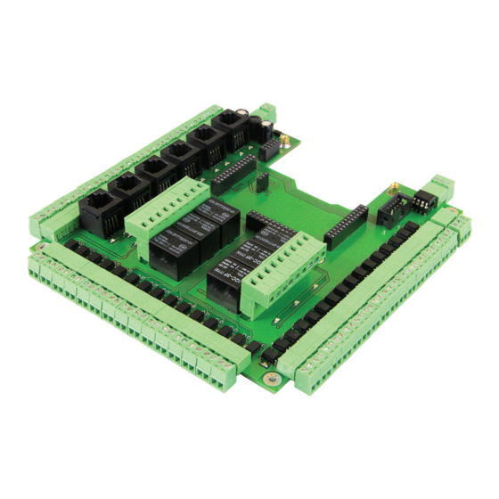
• Frequency converter support (adjustment of spindle rotations, PWM voltage converter) from control program (MACH) PWM signal. • Control of six high-current relays 6A/220V for commutation of supplementary CNC machine devices (spindles, coolant system pump or electric fan). Relay states are indicated by LEDs. Fig. 1. PLCM-B1 dimensions... -
Page 4: Sockets Purpose And Indication
PLCM-B1 Breakout board for PLCM-E3/E3p controller 19.04.13 revision 5. SOCKETS PURPOSE AND INDICATION XP80 (terminal socket) – socket backup of PLCM-E3/E3p module Analog-to-Digital convertors (ADC). It isn’t used in the current software versions. P1/p12 XS1-XS5 (pin connector) – sockets for PLCM-E3/E3p module connectors. - Page 5 PLCM-B1 Breakout board for PLCM-E3/E3p controller 19.04.13 revision...
-
Page 6: Connection
Connection to PLCM-E3/E3p It is necessary to close JP3 jumper. PLCM-E3/E3p board is connected with PLCM-B1 module by XS1-XS5 pin connectors. It is necessary to connect two boards same as shown in drawing and to fix PLCM-E3/E3p board by using M3 screws. -
Page 7: Pwm Voltage Converter
PLCM-B1. In that case it is necessary frequency is changing). FT PWM control signal is generated by to apply voltage only to one of devices. Power supply of PLCM-B1 MACH3 CNC control program. and power supply of PLCM-E3 by USB or PoE is possibly, but in this Frequency transformer is connected to XP79 according to fig. - Page 8 Pay attention that documentation can be changed due to constant technical upgrading of production. You can download last versions from www.purelogic.ru www.purelogic.ru address: Bld. 160, Leninsky prospect, Voronezh city, 394033, Russia phone: +7 (495) 505-63-74, +7 (473) 204-51-56 e-mail: info@purelogic.ru...
Need help?
Do you have a question about the PLCM-B1 and is the answer not in the manual?
Questions and answers