
Related Manuals for Ferroli RHA series


Summary of Contents for Ferroli RHA series
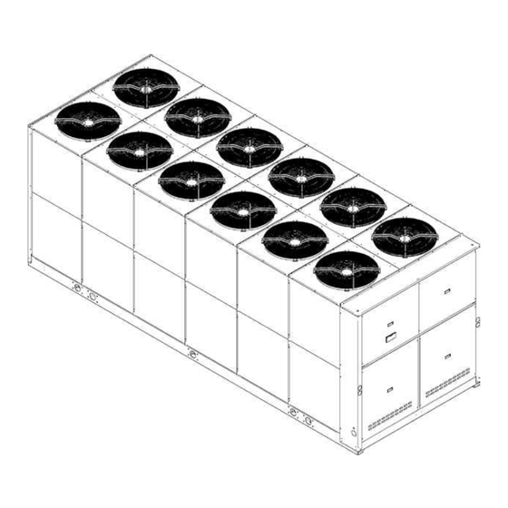
- Page 1 AIR COOLED WATER CHILLERS AND HEAT PUMPS WITH AXIAL FANS 351 ÷ 625 kW in cooling mode 370 ÷ 658 kW in heating mode INSTALLATION MANUAL...
- Page 2 Dear Customer, Thank you for having purchased a FERROLI Idustrial coolers. It is the result of many years experience, particular research and has been made with top quality materials and higlly advanced technologies.The CE mark guaranteed thats the appliances meets Euro- pean Machine Directive requirements regarding safety.
-
Page 3: Table Of Contents
TABLE OF CONTENTS THIS MANUAL IS DIVIDED INTO SECTIONS. THEIR NAMES APPEAR IN THE HEADING OF EACH PAGE. GENERAL SPECIFICATIONS....... 4 Acoustic Version: AS (Low noise Unit) . -
Page 4: General Specifications
Maximum pressure - Low Side Maximum pressure - Low Side PED certification authority PED certification authority Ferroli Spa Via Ritonda 78/A NOTE: The identification plate of the Brine Unit (BR - BP) is filled out as (VR) Italy shown in the diagram for the Basic Version of the unit (VB). -
Page 5: Presentation Of The Unit
GENERAL SPECIFICATIONS Presentation of the unit This new series of industrial chillers and heat pumps has been designed to meet the demands of global markets in the medium-big power industrial and commercial plants. Units are compact and highly configurable, built to fit different types of plants so to meet the needs of highly qualified engineers. -
Page 6: Description Of The Components
GENERAL SPECIFICATIONS Description of the components 1. Fans. These are the helical type with scythe-shaped blades to increase the efficiency and reduce the noise level. The fans are directly coupled to the single-phase motor by means of an external rotor. Thermal protection against operating faults is installed insi- de the winding. - Page 7 GENERAL SPECIFICATIONS 7. Condensing coils, the aluminium finned pack type with shaped profile to increase the heat exchange coefficient and with copper pipes arranged in staggered rows. A sub-cooling section is integrated into the lower part. 8. Covering panels, made of galvanized sheet metal coated with polyurethane powder paint to ensure maximun protection against adverse weather conditions 9.One-way valves (IP unit only), allowing the coolant to pass into the appropriate exchangers, depending on the operating cycle.
-
Page 8: Version With Desuperheater Vd (Available For Both Ir Units And Ip Units)
GENERAL SPECIFICATIONS Version with Desuperheater VD (available for both IR units and IP units) Hydraulic and chilling circuit components: 1. Desuperheater. Specially designed for the specific version. Plate type, made of stainless steel (AISI 316). There are installed within a shell of thermal barrier insulating material to prevent heat exchanges towards the outside. Standard supply also includes an electric antifreeze heater to prevent the parts from freezing during the winter, when the system remains at a standstill (if not drained). -
Page 9: Accessories And Optional Equipment
ACCESSORIES AND OPTIONAL EQUIPMENT Mechanical accessories NOTE: The accessories can be of the following type: (M): only installed in the factory. (F): supplied for installation by the customer. MP. Hydronic Kit (M). Consists of: 1 On-off ball valves. Turn components such as the water filter, surge chamber and pump on and off when they require routine or extraordinary maintenance. - Page 10 ACCESSORIES AND OPTIONAL EQUIPMENT NOTE: The accessories can be of the following type: (M): only installed in the factory. (F): supplied for installation by the customer. SAA- Water Storage tank (M). Painted steel water storage tank reduces compressor startup frequency and temperature fluctuation on water side.
- Page 11 ACCESSORIES AND OPTIONAL EQUIPMENT COMPLETE PIPE KIT wATER STORAGE TANK PIPE KIT VICTAULIC CONNECTION KIT M1P AM 2P HP1 M1P PS 2P STD M1P AM 2P STD M2P AM 2P HP1 M2P PS 2P STD M2P AM 2P STD M1P SS 2P HP1 M1P SS 2P STD M2P SS 2P HP1 M2P SS 2P STD...
-
Page 12: Electrical Accessories
ACCESSORIES AND OPTIONAL EQUIPMENT Electrical accessories TP - Low and High pressure transducers (M). Allow the display of the suction and discharge pressures of compressors. Their presence activates an advanced defrost and condensation control logic and the ATC (Advanced Temperature Control) to prevent high pressure alarm due to high external air temperature. -
Page 13: General Technical Specification
GENERAL TECHNICAL SPECIFICATION General technical specifications MODELS 350.5 390.6 440.6 490.6 560.6 630.6 Power supply 400-3-50 V-ph-Hz Refrigerant type R410A Refrigeration circuits N° Compressor specifications Type scroll Quantity N° Oil charge CP1 Oil charge CP2 Oil charge CP3 Oil charge CP4 Oil charge CP5 Oil charge CP6 0 / 20 / 40 / 60... -
Page 14: Nominal Performances
NOMINAL PERFORMANCES Standard unit AB - MEDIUM TEMPERATURE PLANT - Data certified by EUROVENT MOD. 350.5 390.6 440.6 490.6 560.6 630.6 Cooling mode A35W7 (source: air 35°C d.b. / system: water in 12°C out 7°C) Cooling capacity (E) Compressor power input Total power input EER (E) 2.93... -
Page 15: Standard Unit Ab - Medium Temperature Plant - Data Declared According To Uni En 14511
NOMINAL PERFORMANCES Standard unit AB - MEDIUM TEMPERATURE PLANT - Data declared according to UNI EN 14511 MOD. 350.5 390.6 440.6 490.6 560.6 630.6 Cooling mode A35W7 (source: air 35°C d.b. / system: water in 12°C out 7°C) Cooling capacity Compressor power input Total power input 2.83... -
Page 16: Low Noise Unit As - Medium Temperature Plant - Data Certified By Eurovent
NOMINAL PERFORMANCES Low noise unit AS - MEDIUM TEMPERATURE PLANT - Data certified by EUROVENT MOD. 350.5 390.6 440.6 490.6 560.6 630.6 Cooling mode A35W7 (source: air 35°C d.b. / system: water in 12°C out 7°C) Cooling capacity (E) Compressor power input Total power input EER (E) 2.65... -
Page 17: Low Noise Unit As - Medium Temperature Plant - Data Declared According To Uni En 14511
NOMINAL PERFORMANCES Low noise unit AS - MEDIUM TEMPERATURE PLANT - Data declared according to UNI EN 14511 MOD. 350.5 390.6 440.6 490.6 560.6 630.6 Cooling mode A35W7 (source: air 35°C d.b. / system: water in 12°C out 7°C) Cooling capacity Compressor power input Total power input 2.60... -
Page 18: Extra Low Noise Unit Ax - Medium Temperature Plant - Data Certified By Eurovent
NOMINAL PERFORMANCES Extra low noise unit AX - MEDIUM TEMPERATURE PLANT - Data certified by EUROVENT MOD. 350.5 390.6 440.6 490.6 560.6 630.6 Cooling mode A35W7 (source: air 35°C d.b. / system: water in 12°C out 7°C) Cooling capacity (E) Compressor power input Total power input EER (E) -
Page 19: Extra Low Noise Unit Ax - Medium Temperature Plant - Data Declared According To Uni En 14511
NOMINAL PERFORMANCES Extra low noise unit AX - MEDIUM TEMPERATURE PLANT - Data declared according to UNI EN 14511 MOD. 350.5 390.6 440.6 490.6 560.6 630.6 Cooling mode A35W7 (source: air 35°C d.b. / system: water in 12°C out 7°C) Cooling capacity Compressor power input Total power input... -
Page 20: Standard Performances - Ir Cooling Unit Only
STANDARD PERFORMANCES - IR COOLING UNIT ONLY Performances - Standard unit AB OUTDOOR AIR TEMPERATURE (°C D.B.) MOD. 45 (1) 50 (1) (2) 73.7 84.8 93.4 74.4 85.6 94.3 75.1 86.4 95.2 76.0 87.4 96.3 350.5 76.7 88.3 97.3 77.5 89.1 98.2 78.2... -
Page 21: Performances - Low Noise Unit As
STANDARD PERFORMANCES - IR COOLING UNIT ONLY Performances - Low noise unit AS OUTDOOR AIR TEMPERATURE (°C D.B.) MOD. 50 (2) 79.3 91.2 80.0 92.1 80.8 93.0 81.7 94.0 350.5 82.6 95.0 83.4 95.9 84.2 96.9 85.0 97.8 86.3 99.3 87.1 88.0 89.0... -
Page 22: Performances - Extra Low Noise Unit Ax
STANDARD PERFORMANCES - IR COOLING UNIT ONLY Performances - Extra low noise unit AX OUTDOOR AIR TEMPERATURE (°C D.B.) MOD. 45 (1) 50 (1) (2) 82.1 94.5 82.9 95.3 83.7 96.3 84.6 97.4 350.5 85.5 98.4 86.3 99.3 87.2 88.0 89.1 89.9 90.9... -
Page 23: Standard Performances - Ip Heat Pump Units
STANDARD PERFORMANCES - IP HEAT PUMP UNITS Performances in cooling mode - Standard Unit AB OUTDOOR AIR TEMPERATURE (°C D.B.) MOD. 50 (2) 73.0 84.0 92.5 73.7 84.7 93.4 74.4 85.6 94.3 75.2 86.6 95.4 350.5 76.0 87.4 96.3 76.7 88.3 97.3 77.5... -
Page 24: Performances In Heating Mode - Standard Unit Ab
STANDARD PERFORMANCES - IP HEAT PUMP UNITS Performances in heating mode - Standard Unit AB OUTDOOR AIR TEMPERATURE (°C D.B.) MOD. 75.5 75.9 77.0 77.4 78.3 79.2 80.1 83.6 84.1 85.3 85.8 86.8 87.8 88.8 350.5 93.0 93.5 94.8 95.4 96.5 97.6 98.7... -
Page 25: Performances In Cooling Mode - Low Noise Unit As
STANDARD PERFORMANCES - IP HEAT PUMP UNITS Performances in cooling mode - Low noise Unit AS OUTDOOR AIR TEMPERATURE (°C D.B.) MOD. 45 (1) 50 (1) (2) 78.6 90.4 99.6 79.3 91.3 80.1 92.2 81.0 93.2 350.5 81.8 94.2 82.6 95.1 83.5 96.0... -
Page 26: Performances In Heating Mode - Low Noise Unit As
STANDARD PERFORMANCES - IP HEAT PUMP UNITS Performances in heating mode - Low noise Unit AS OUTDOOR AIR TEMPERATURE (°C D.B.) MOD. 75.5 75.9 77.0 73.8 74.6 75.5 76.3 83.6 84.1 85.3 81.7 82.7 83.6 84.6 350.5 93.0 93.5 94.8 90.9 91.9 93.0... -
Page 27: Performances In Cooling Mode - Extra Low Noise Unit Ax
STANDARD PERFORMANCES - IP HEAT PUMP UNITS Performances in cooling mode - Extra low noise Unit AX OUTDOOR AIR TEMPERATURE (°C D.B.) MOD. 45 (1) 50 (1) (2) 80.7 92.8 81.4 93.7 82.3 94.7 83.2 95.7 350.5 84.0 96.7 84.9 97.6 85.7 98.6... -
Page 28: Performances In Heating Mode - Extra Low Noise Unit Ax
STANDARD PERFORMANCES - IP HEAT PUMP UNITS Performances in heating mode - Extra low noise Unit AX OUTDOOR AIR TEMPERATURE (°C D.B.) MOD. 73.2 73.6 74.7 72.0 72.8 73.7 74.5 81.1 81.6 82.7 79.8 80.7 81.6 82.6 350.5 90.2 90.7 92.0 88.7 89.7... -
Page 29: Correction Factor For The Use Of Glycol
CORRECTION FACTOR FOR THE USE OF GLYCOL Correction factor for the use of glycol IN HEATING MODE ETHYLENE GLYCOL with water produced between 30 ÷ 55 º C. Percentage Of glycol in mass / volume 0 / 0 10 / 8.9 20 / 18.1 30 / 27.7 40 / 37.5... -
Page 30: General Specifications - Brine Unit Br - Bp
GENERAL SPECIFICATIONS - BRINE UNIT BR - BP Brine Unit (BR) Correction factors to apply to the basic version data ETHYLENE GLYCOL percentage of glycol in mass / volume 20 / 18.1 freezing point [°C] Produced water temperature Cooling capacity CCPF 0.912 0.855 0.798... -
Page 31: General Specifications - Version With Desuperheater
GENERAL SPECIFICATIONS - VERSION wITH DESUPERHEATER (VD) IR COOLING UNIT ONLY Acoustic Version: AB (Standard Unit) Recovery heat exchanger specifications MODEL 350.5 390.6 440.6 490.6 560.6 630.6 Type of recovery exchanger Brazed plates Quantity N° Max. operating pressure on wet side Total water content of recovery exchangers Unit specification Cooling capacity VD(1) -
Page 32: Performances Version With Desuperheater (Vd)
GENERAL SPECIFICATIONS - VERSION wITH DESUPERHEATER (VD) IR COOLING UNIT ONLY Performances Version with Desuperheater (VD) OUTDOOR AIR TEMPERATURE (°C D.B.) MOD. kWtr = Recovered HEATING CAPACITY [kW] 73.6 83.7 95.3 73.1 83.2 94.7 71.2 80.9 92.2 67.7 77.0 87.7 99.5 350.5 62.7... -
Page 33: General Specifications - Version With Desuperheater
GENERAL SPECIFICATIONS - VERSION wITH DESUPERHEATER (VD) IP HEAT PUMP UNIT Acoustic Version: AB (Standard Unit) Recovery heat exchanger specifications MODEL 350.5 390.6 440.6 490.6 560.6 630.6 Type of recovery exchanger Brazed plates Quantity N° Max. operating pressure on wet side Total water content of recovery exchangers Unit specification Cooling capacity VD(1) -
Page 34: Performances Version With Desuperheater (Vd)
GENERAL SPECIFICATIONS - VERSION wITH DESUPERHEATER (VD) IP HEAT PUMP UNIT Performances Version with Desuperheater (VD) OUTDOOR AIR TEMPERATURE (°C D.B.) MOD. kWtr = Recovered HEATING CAPACITY [kW] 71.5 81.3 92.6 71.0 80.8 92.0 69.1 78.6 89.6 65.7 74.8 85.2 96.7 350.5 60.9... -
Page 35: General Specifications - Full Heat Recovery Unit (Vr) Ip Heat Pump Unit
GENERAL SPECIFICATIONS - FULL HEAT RECOVERY UNIT (VR) IP HEAT PUMP UNIT Acoustic Version: AB (Basic Unit) Recovery heat exchanger specifications MODEL 350.5 390.6 440.6 490.6 560.6 630.6 Type of recovery exchanger Brazed plates Quantity N° Max. operating pressure on wet side Total water content of recovery exchangers 28.8 30.4... -
Page 36: Full Heat Recovery Unit Performances (Vr)
GENERAL SPECIFICATIONS - FULL HEAT RECOVERY UNIT (VR) IP HEAT PUMP UNIT Full Heat recovery unit performances (VR) OUTDOOR AIR TEMPERATURE (°C D.B.) MOD. kWtr = Recovered HEATING CAPACITY [kW] 350.5 390.6 440.6 490.6 560.6 630.6 Twe= Evaporator outlet water temperature °C Twr= Recovery outlet water temperature °C The standard performances refer to a 5°C temperature difference between the water entering and leaving the heat exchanger and to operation of the unit with all fans at nominal or maximum speed. -
Page 37: Noise Levels
NOISE LEVELS The noise levels refer to units operating in the nominal conditions (water temperature: inlet: 12°C - outlet: 7°C, Outdoor air tempera- ture: inlet: 30°C - outlet: 35°C). The acoustic pressure levels are measured 1/ 5 / 10 meters away from the outer surface of the unit operating in the free field and resting on a reflecting surface (directional factor of 2). -
Page 38: Operating Range
OPERATING RANGE Operating range The table below lists the operating ranges within which correct operation of the units is guaranteed, depending on the Version and Operating Mode available for each type of unit. Remember that in Heat Pump units, heat recovery only takes place during operation in the cooling mode. Operating range of Standard unit Thermal gradient of the water* Limit value... -
Page 39: Water Pressure Drop Evaporator
wATER PRESSURE DROP EVAPORATOR... -
Page 40: Water Pressure Drop Desuperheater
wATER PRESSURE DROP DESUPERHEATER... -
Page 41: Working Head Of The Pumping Module Mp Am Std And Mp Ss Std
wORKING HEAD OF THE PUMPING MODULE MP AM STD AND MP SS STD... -
Page 42: High Working Head Of The Pumping Module Mp Am Hp1 And Mp Ss Hp1
HIGH wORKING HEAD OF THE PUMPING MODULE MP AM HP1 AND MP SS HP1... -
Page 43: Reception And Positioning
RECEPTION AND POSITIONING Inspections on arrival As soon as the appliance is consigned, it is essential to make sure that all the ordered items have been received and that the shipment is complete. Carefully check that the equipment has not been damaged. If visible damage is discovered, immediately inform the haulage contractor and write “Collected with reserves owing to evident damage”... -
Page 44: Storage
RECEPTION AND POSITIONING Storage The units must be stored in a dry place, sheltered from the sun, rain, sand and wind. Comply with the storage conditions given below: • Do not stack the units • Maximum temperature = 60°C • Minimum temperature = -10°C •... -
Page 45: Dimensional Data
DIMENSIONAL DATA Overall dimensions Mod. 350.5 ÷ 490.6 Mod. 560.6 ÷ 630.6 Description of the components VICTAULIC CONNECTION KIT 1 - Access panel to electric panel’s power section 9 - Water inlet AM PS SS 2 - Access panel to compressor compartment 10 - Water outlet AM PS 3 - Vibration damper fixing holes (6 pcs) 11 - Water outlet SS... -
Page 46: Minimum Space Required For Operation
DIMENSIONAL DATA Minimum space required for operation To correctly install, maintain and achieve the best efficiency of the unit, comply with the measurements for the free area that must be left around the machine, as shown in the figure. This will ensure good air circulation, allow the unit to operate correctly and facilitate future maintenance work. -
Page 47: Weight During Transport
wEIGHT DURING OPERATION AND TRANSPORT weight during transport To correctly install the unit, comply with the measurements for the free area that must be left around the machine, as shown in the drawing. UNIT wITHOUT WATER STORAGE TANK Unit WITHOUT Hydronic Kit IR Version IP Version AB-AS... -
Page 48: Weight During Operation
wEIGHT DURING OPERATION AND TRANSPORT weight during operation UNIT wITHOUT WATER STORAGE TANK IR VERSION Unit WITHOUT Hydronic Kit AB-AS Acustic version Center of gravity Center of gravity Total Total Load on bearing points [Kg] Load on bearing points [Kg] position [mm] position [mm] Mod. - Page 49 wEIGHT DURING OPERATION AND TRANSPORT UNIT wITHOUT WATER STORAGE TANK IP VERSION Unit WITHOUT Hydronic Kit AB-AS Acustic version Center of gravity Center of gravity Total Total Load on bearing points [Kg] Load on bearing points [Kg] position [mm] position [mm] Mod.
-
Page 50: Hydraulic Connections
HYDRAULIC CONNECTIONS General rules A mesh filter (hole Ø ≤ 500 µm) must be installed on the unit’s water inlet and/or water tank otherwise warranty is imme- diately forfeited. The filter performs the function of blocking any foreign matter in the system’s piping circuit (shavings, machining debris, etc.). -
Page 51: Basic Diagram Standard Unit Vb [Plant Side Water Circuit]
HYDRAULIC CONNECTIONS Basic diagram Standard Unit VB [PLANT SIDE wATER CIRCUIT] The following figures represent connections to the plant side exchanger. IMPORTANT: There must be a constant flow of water to the exchanger. With accessory primary-secondary pumping module MP PS STD is mandatory to install a water filter in the secondary circuit immediately after of the water tank. -
Page 52: Air Vent And Water Drain
HYDRAULIC CONNECTIONS Air vent and water drain On the piping circuit feeding the unit, especially when equipped with the Victaulic connection kit, the installer must fit an appropriate number of valves (manual or automatic) at the top of the circuit in order to vent any air in the piping system. In the same way, he must install a water drain valve in order, when necessary, to drain the unit’s plate exchanger completely (especially during the winter in order to prevent freezing that would seriously jeopardize the operation of the unit). - Page 53 HYDRAULIC CONNECTIONS ISO-G DN(mm) EXTERNAL DIAMETER OD(mm) 1” 33.7 15.875 7.137 30.226 1.600 1.651 11/4” 42.4 15.875 7.137 38.989 1.600 1.651 11/2” 48.3 15.875 7.137 45.085 1.600 1.651 2” 60.3 15.875 8.738 57.150 1.600 1.651 21/2” 76.1 15.875 8.738 72.260 1.981 2.108 3”...
-
Page 54: Electrical Connections
ELECTRICAL CONNECTIONS General rules The appliance must be wired in compliance with the laws in force in the country in which it is installed. The units are supplied fully wired in the factory and pre-engineered for connection to the electricity main. The electric panel is made in compliance with the tech- nical standards in force in the European Union. - Page 55 ELECTRICAL CONNECTIONS Single Fan specifications UNIT 350.5 390.6 440.6 490.6 560.6 630.6 400 - 3 - 50 V-ph-Hz Power supply 15.0 Summary Fan specifications UNIT 350.5 390.6 440.6 490.6 560.6 630.6 400 - 3 - 50 V-ph-Hz Power supply 34.4 43.0 51.6 16.0...
- Page 56 ELECTRICAL CONNECTIONS 1) Connection to the electricity main • Power supply line; The machine’s power supply line must be laid by following a clearly defined route in order to make it as correct as possible any without any breaks. Pass the line through the opening on the button of the electrical panel. Secure the line integral with the structure of the machine.
-
Page 57: R410A Protection Devices
R410A PROTECTION DEVICES Protection devices HIGH PRESSURE The unit is protected against risk of overpressure by means of 5 levels protection chain. Each circuit is equipped with: 1) ATC (Cooling Capacity Control) 2) high pressure transducer connected to electronic controller (if installed) 3) high pressure automatic switch connected to electronic controller 4) high pressure manual switch connected to compressor contactor command 5) high pressure safety valve... -
Page 58: Serial Interface: Rs485 Modbus® Rtu
SERIAL INTERFACE: RS485 MODBUS® RTU Protection devices HIGH PRESSURE Through the accessory interface RS485 MODBUS ® RTU control system is able to communicate with the outside world. The outside world means a master device, usually a supervisory system or a BMS (Building Management System), designed by the customer. CAUTION : The use of serial communication must be made by qualified personnel. - Page 59 SERIAL INTERFACE: RS485 MODBUS® RTU MODBUS ® Address Table: Pumps Level Type Decimal Modbus Parameter/Description Def Min U.M. Modbus R/W Notes/Meaning Position Pump A evaporator status 1525 05F5 0 = off 1 = on Pump B evaporator status 1526 05F6 Enabling pump A evaporator 1127 0467...
- Page 60 SERIAL INTERFACE: RS485 MODBUS® RTU MODBUS ® Address Table: Fans Level Type Decimal Modbus Parameter/Description U.M. Modbus R/W Notes/Meaning Position Circuit 1 fans power 1567 061F Circuit 2 fans power 1568 0620 0 = not active ALARM Circuit 1 fans thermal 1286 0506 1 = active...
-
Page 61: Refrigerant Flow Diagram - Standard Unit Vb
REFRIGERANT FLOw DIAGRAM - STANDARD UNIT VB Refrigerant flow diagram in cooling mode IR... -
Page 62: Refrigerant Flow Diagram In Heating Mode Ip
REFRIGERANT FLOw DIAGRAM - STANDARD UNIT VB Refrigerant flow diagram in heating mode IP... -
Page 63: Refrigerant Flow Diagram - Desuperheaters Unit Vd
REFRIGERANT FLOw DIAGRAM - DESUPERHEATERS UNIT VD Refrigerant flow diagram in cooling mode IR... -
Page 64: Refrigerant Flow Diagram In Heating Mode Ip
REFRIGERANT FLOw DIAGRAM - DESUPERHEATERS UNIT VD Refrigerant flow diagram in heating mode IP... -
Page 65: Start-Up
START-UP General Rules To validate the contractual warranty, the machine must be set at work by technicians from an authorized assistance center. Before they are called, check to make sure that all parts of the installation have been completed, the unit levelled, the wet connections made with the relative air vent and the electrical connections made. - Page 66 MAINTENANCE • Inspection of the condensing system wARNING: The finned pack exchanger has fins made of aluminium or some other thin material, thus even accidental contact could cause cuts. Comply with the instructions in the relative section. • Condensing coils In view of the function of this component, it is very important for the surface of the exchanger to be as free as possible from clogging caused by items that could reduce the fan’s air flow rate and, thus, the performances of the unit itself.
-
Page 67: General Considerations
MAINTENANCE General considerations The machine has been designed with a view to reducing the risks to persons and the environment in which it is installed, to the mi- nimum. To eliminate residue hazards, it is therefore advisable to become as familiar as possible with the machine in order to avoid accidents that could cause injuries to persons and/or damage to property. -
Page 68: Safety And Pollution
SAFETY AND POLLUTION Refrigerant safety card 1 SUPPLIER COMPANY AND PRODUCT IDENTIFICATION Card No. FRIG 8 Product R-410A Supplier company identification RIVOIRA SpA 2 COMPOSITION / INFORMATION ON INGREDIENTS Substance / Preparation Preparation Components / Impurities Contains the following components : Difluoromethane (R32) 50 % in weight Pentafluoroethane (R125) 50 % in weight... - Page 69 SAFETY AND POLLUTION 12 ECOLOGICAL INFORMATION Effects linked to ecotoxicity Pentafluoroethane (R125) Potential global warming with halocarbides; HGWP (R-11 = 1) = 0.84 Potential impoverishment of the ozone; ODP (R-11 = 1) = 0 13 CONSIDERATIONS ON DISPOSAL General Do not dispose of where accumulation can be hazardous. Usable with reconditioning.
-
Page 70: First Aid
SAFETY AND POLLUTION First aid • Move the victim away from the toxic source, keep him warm and allow him to rest. • Administer oxygen if necessary. • Proceed with artificial respiration if necessary. • Give heart massage in the case of heart failure. •... - Page 71 NOTE...
- Page 72 Ferroli spa ¬ 37047 San Bonifacio (Verona) Italy ¬ Via Ritonda 78/A tel. +39.045.6139411 ¬ fax +39.045.6100933 ¬ www.ferroli.it...
Need help?
Do you have a question about the RHA series and is the answer not in the manual?
Questions and answers