
Related Manuals for Ferroli RGA Series


Summary of Contents for Ferroli RGA Series
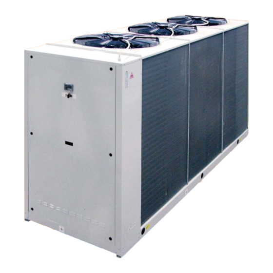
- Page 1 AIR COOLED WATER CHILLERS AND HEAT PUMPS WITH AXIAL FANS 53.5 ÷ 200 kW IN COOLING MODE 57.5 ÷ 214 kW IN HEATING MODE TECHNICAL MANUAL...
- Page 2 The manufacturer declines all responsibility for any inaccuracies in this manual due to printing or typing errors. The reserves the right to modify the products contents in this catalogue without previous notice.
-
Page 3: Table Of Contents
TABLE OF CONTENTS THIS MANUAL IS DIVIDED INTO SECTIONS. THEIR NAMES APPEAR IN THE HEADING OF EACH PAGE. GENERAL SPECIFICATIONS ....... . .5 CORRECTION FACTOR FOR THE USE OF GLYCOL . -
Page 5: General Specifications
GENERAL SPECIFICATIONS Unit description This new series of industrial chillers and heat pumps has been designed to meet the demands of global markets in the small- medium power industrial and commercial plants. Units are compact and highly configurable, built to fit different types of plants so to meet the needs of highly qualified engineers. -
Page 6: Description Of The Components
GENERAL SPECIFICATIONS Description of the components The complete series of industrial chillers and heat pumps for use in hydronic systems includes 12 constructional sizes rang from 53.5 to 200 kW in the cooling mode and from 57.5 to 214 kW in the heating mode. Main components: 1. - Page 7 GENERAL SPECIFICATIONS 3. Compressors. They are the SCROLL type with orbiting coil equipped with built-in thermal protection and oil heater. The AS unit includes: a soundproofing jacket for the compressors, an acoustic cladding around the compartment where they are hou- sed, to reduce noise level, and reduced rotating speed of axial fans;...
-
Page 8: Hydraulic And Cooling Circuit Components
GENERAL SPECIFICATIONS Hydraulic and cooling circuit components 10. Safety valve. Installed on the delivery pipe of the compressors, this operates if extreme faults should occur in the plant. 11. Fluid cock. Ball type, this allows the gas flow on the fluid line to be turned on and off. Along with the cock on the compres- sor delivery, it allows the components of the fluid line to be subjected to extraordinary maintenance work and the compressors to be replaced if necessary (without discharging the coolant from the unit). -
Page 9: Desuperheater Unit Vd
GENERAL SPECIFICATIONS Desuperheater unit VD (available for both IR units and IP units) Hydraulic and chilling circuit components: 1. Desuperheater. Specially designed for the specific version. Plate type, made of stainless steel (AISI 316). It is installed within a shell of thermal barrier insulating material to prevent heat exchanges towards the outside. Standard supply also includes an electric antifreeze heater to prevent the parts from freezing during the winter, when the system remains at a stand- still (if not drained). -
Page 10: Total Heat Recovery Unit Vr
GENERAL SPECIFICATIONS Total Heat Recovery unit VR (only available for IR units) Hydraulic and cooling circuit components: 1. Heat recovery exchanger. Specially designed for the specific version. Plate type, made of stainless steel (AISI 316). It is installed within a shell of thermal barrier insulating material to prevent heat dispersion towards the outside. Standard supply also includes an electric antifreeze heater to prevent the parts from freezing during the winter, if is it not drained. -
Page 11: Accessories And Optional Equipment
ACCESSORIES AND OPTIONAL EQUIPMENT Accessories AVG - Rubber vibration dampers. Consisting of 4/6 rubber vibration dampers to fit under the unit. Reduce the extent to which the mechanical vibrations created by the compressors and fans during normal operation are trans- mitted to the bearing surface of the machine. - Page 12 ACCESSORIES AND OPTIONAL EQUIPMENT MP. Hydronic Kit. MP : Hydronic Kit with 1 o 2 Pumps (The second pump, mounted in parallel to the first, allows to have a spare pump to be activated in case of failure of the first). Besides the pumps, this accessory is equipped with all the hydraulic compo- nents (water filter, expansion tank, on-off valves, water pressure gauge, air vent, water outlet) required for complete installa- tion and easy maintenance.
- Page 13 ACCESSORIES AND OPTIONAL EQUIPMENT VICTAULIC CONNECTION KIT COMPLETE PIPE KIT WATER STORAGE TANK PIPE KIT M1P AM 2P STD M1P AM 2P HP1 M1P PS 2P STD M2P AM 2P STD M2P AM 2P HP1 M2P PS 2P STD M1P SS 2P STD M1P SS 2P HP1 M2P SS 2P HP1 M2P SS 2P STD...
-
Page 14: Mechanical Options
ACCESSORIES AND OPTIONAL EQUIPMENT CR - Remote control (F). This can be used to select all the monitoring and display functions of the control unit on the machine at a maximum distance of 100 meters away. It must be installed by using a cable with three strands or three wires in PVC of the N07-VK type with a 1mm section. -
Page 15: Technical Specifications And Standard Performances - Ir Cooling Unit Only
TECHNICAL SPECIFICATIONS AND STANDARD PERFORMANCES - IR COOLING UNIT ONLY Technical specifications of unit AB Standard Unit Model Power supply 400V - 3ph+N - 50 Hz 400V - 3ph - 50 Hz V-f-Hz Type of refrigerant R410A Circuits n° Cooling capacity (1) (E) 53.5 58.6 68.8... -
Page 16: Standard Performances Ab Standard Unit
TECHNICAL SPECIFICATIONS AND STANDARD PERFORMANCES - IR COOLING UNIT ONLY Standard performances AB Standard unit Mod. 50-100 OUTDOOR AIR TEMPERATURE (°C D.B.) MOD. 61.1 11.6 57.0 13.3 53.9 14.7 50.6 16.2 47.1 17.8 43.6 19.4 40.0 21.0 62.8 11.7 58.6 13.4 55.4 14.8... - Page 17 TECHNICAL SPECIFICATIONS AND STANDARD PERFORMANCES - IR COOLING UNIT ONLY Mod. 115-200 OUTDOOR AIR TEMPERATURE (°C D.B.) MOD. 24.9 28.7 31.6 34.8 98.5 38.4 91.3 41.8 83.8 45.2 25.1 28.9 31.9 35.1 38.7 93.8 42.2 86.1 45.7 25.4 29.2 32.2 35.5 39.1 96.5...
-
Page 18: Technical Specifications Of Unit As Low Noise Unit
TECHNICAL SPECIFICATIONS AND STANDARD PERFORMANCES - IR COOLING UNIT ONLY Technical specifications of unit AS Low noise unit Model Power supply 400V - 3ph+N - 50 Hz 400V - 3ph - 50 Hz V-f-Hz Type of refrigerant R410A Circuits n° Cooling capacity (1) (E) 51.9 56.8... -
Page 19: Standard Performances As Low Noise Unit
TECHNICAL SPECIFICATIONS AND STANDARD PERFORMANCES - IR COOLING UNIT ONLY Standard performances AS Low noise unit Mod. 50-100 OUTDOOR AIR TEMPERATURE (°C D.B.) MOD. 59.2 12.1 55.3 13.9 52.3 15.3 49.1 16.9 45.7 18.6 42.3 20.3 38.8 22.0 60.9 12.2 56.8 14.0 53.7... - Page 20 TECHNICAL SPECIFICATIONS AND STANDARD PERFORMANCES - IR COOLING UNIT ONLY Mod. 115-200 OUTDOOR AIR TEMPERATURE (°C D.B.) MOD. 26.0 30.0 33.0 36.4 95.9 40.1 88.8 43.7 81.6 47.3 26.3 30.2 33.3 36.7 98.5 40.5 91.3 44.1 83.8 47.7 26.5 30.5 33.6 37.1 40.9...
-
Page 21: Technical Specifications Of Unit Ax Extra Low Noise Version
TECHNICAL SPECIFICATIONS AND STANDARD PERFORMANCES - IR COOLING UNIT ONLY Technical specifications of unit AX Extra low noise unit Model Power supply 400V - 3ph+N - 50 Hz 400V - 3ph - 50 Hz V-f-Hz Type of refrigerant R410A Circuits n°... - Page 22 TECHNICAL SPECIFICATIONS AND STANDARD PERFORMANCES - IR COOLING UNIT ONLY Standard performances AX Extra low noise unit Mod. 50-100 OUTDOOR AIR TEMPERATURE (°C D.B.) MOD. 57.9 12.3 54.0 14.2 51.1 15.7 47.9 17.3 44.6 19.0 41.3 20.7 37.9 22.4 59.5 12.5 55.5 14.3...
- Page 23 TECHNICAL SPECIFICATIONS AND STANDARD PERFORMANCES - IR COOLING UNIT ONLY Mod. 115-200 OUTDOOR AIR TEMPERATURE (°C D.B.) MOD. 26.9 30.9 34.1 37.6 93.2 41.4 86.4 45.1 79.3 48.8 27.1 31.2 34.4 37.9 95.8 41.8 88.8 45.6 81.5 49.3 27.4 31.5 34.7 38.3 98.6...
-
Page 24: Desuperheater Unit (Vd)
TECHNICAL SPECIFICATIONS AND STANDARD PERFORMANCES - IR COOLING UNIT ONLY Desuperheater unit (VD) Standard Unit AB Recovery heat exchanger specifications MODEL Type of recovery exchanger STAINLESS STEEL BRAZE PLATES Quantity n° Total water content of recovery exchangers Max. operating pressure on wet side Unit specification Cooling capacity VD(1) 55.6... -
Page 25: Recovered Heating Capacity Desuperheater Unit (Vd)
TECHNICAL SPECIFICATIONS AND STANDARD PERFORMANCES - IR COOLING UNIT ONLY Recovered heating capacity Desuperheater unit (VD) OUTDOOR AIR TEMPERATURE (°C D.B.) OUTDOOR AIR TEMPERATURE (°C D.B.) MOD. MOD. = RECOVERED HEATING CAPACITY [KW] = RECOVERED HEATING CAPACITY [KW] 12.8 14.7 16.9 19.3 22.0... -
Page 26: Totale Heat Recovery Unit (Vr)
TECHNICAL SPECIFICATIONS AND STANDARD PERFORMANCES - IR COOLING UNIT ONLY Total heat recovery unit (VR) Standard Unit AB Recovery heat exchanger specifications MODEL Type of recovery exchanger STAINLESS STEEL BRAZE PLATES Quantity n° Total water content of recovery exchangers 10.9 12.6 14.5 11.1... -
Page 27: Recovered Heating Capacity Total Heat Recovery Unit (Vd)
TECHNICAL SPECIFICATIONS AND STANDARD PERFORMANCES - IR COOLING UNIT ONLY Recovered heating capacity Total heat recovery unit (VR) TWR - RECOVERY TEMPERATURE (°C) TWR - RECOVERY TEMPERATURE (°C) MOD. MOD. = RECOVERED HEATING CAPACITY [KW] = RECOVERED HEATING CAPACITY [KW] 71.5 69.5 67.3... -
Page 28: Technical Specifications And Standard Performances - Ip Heat Pump Units
TECHNICAL SPECIFICATIONS AND STANDARD PERFORMANCES - IP HEAT PUMP UNITS Technical specifications of unit AB Standard unit Model 400V - 3ph+N - 50 Hz 400V - 3ph - 50 Hz V-f-Hz Power supply Type of refrigerant R410A Circuits n° Cooling capacity (1) (E) 52.9 57.5 67.2... -
Page 29: Standard Performances In Cooling Mode Ab Standard Unit
TECHNICAL SPECIFICATIONS AND STANDARD PERFORMANCES - IP HEAT PUMP UNITS Standard performances in cooling mode AB Standard Unit Mod. 50-100 OUTDOOR AIR TEMPERATURE (°C D.B.) MOD. 60.4 11.7 56.4 13.5 53.3 14.9 50.0 16.4 46.5 18.1 43.1 19.7 39.6 21.3 62.1 11.8 57.9... - Page 30 TECHNICAL SPECIFICATIONS AND STANDARD PERFORMANCES - IP HEAT PUMP UNITS Mod. 115-200 OUTDOOR AIR TEMPERATURE (°C D.B.) MOD. 24.8 28.6 31.5 34.7 96.8 38.3 89.6 41.7 82.3 45.1 25.1 28.8 31.8 35.0 99.4 38.6 92.1 42.1 84.6 45.5 25.3 29.1 32.1 35.4 39.0...
-
Page 31: Standard Performances In Heating Mode Ab Standard Unit
TECHNICAL SPECIFICATIONS AND STANDARD PERFORMANCES - IP HEAT PUMP UNITS Standard performances in heating mode AB Standard Unit OUTDOOR AIR TEMPERATURE (°C D.B.) MOD. 43.9 11.9 50.3 12.0 55.0 12.1 58.5 12.2 62.7 12.3 67.1 12.5 71.7 12.6 43.7 13.2 50.0 13.3 54.7... -
Page 32: Technical Specifications Of Unit As Low Noise Unit
TECHNICAL SPECIFICATIONS AND STANDARD PERFORMANCES - IP HEAT PUMP UNITS Technical specifications of unit AS Low noise Unit Model Power supply 400V - 3ph+N - 50 Hz 400V - 3ph - 50 Hz V-f-Hz R410A Type of refrigerant n° Circuits Cooling capacity (1) (E) 50.8 55.2... -
Page 33: Standard Performances In Cooling Mode As Low Noise Unit
TECHNICAL SPECIFICATIONS AND STANDARD PERFORMANCES - IP HEAT PUMP UNITS Standard performances in cooling mode AS Low noise Unit Mod. 50-100 OUTDOOR AIR TEMPERATURE (°C D.B.) MOD. 58.0 12.5 54.1 14.4 51.2 15.8 48.0 17.5 44.7 19.2 41.4 21.0 38.0 22.7 59.6 12.6... - Page 34 TECHNICAL SPECIFICATIONS AND STANDARD PERFORMANCES - IP HEAT PUMP UNITS Mod. 115-200 OUTDOOR AIR TEMPERATURE (°C D.B.) MOD. 26.5 30.4 33.5 37.0 93.2 40.7 86.4 44.4 79.3 48.0 26.7 30.7 33.8 37.3 95.8 41.1 88.8 44.8 81.5 48.5 27.0 31.0 34.2 37.7 41.6...
-
Page 35: Standard Performances In Heating Mode As Low Noise Unit
TECHNICAL SPECIFICATIONS AND STANDARD PERFORMANCES - IP HEAT PUMP UNITS Standard performances in heating mode AS Low noise Unit OUTDOOR AIR TEMPERATURE (°C D.B.) MOD. 42.8 11.3 49.0 11.4 53.6 11.5 57.0 11.6 61.1 11.7 65.4 11.9 69.9 12.0 42.5 12.5 48.8 12.6... -
Page 36: Technical Specifications Of Unit Ax Extra Low Noise Version
TECHNICAL SPECIFICATIONS AND STANDARD PERFORMANCES - IP HEAT PUMP UNITS Technical specifications of unit AX Extra low noise unit Model 400V - 3ph+N - 50 Hz 400V - 3ph - 50 Hz V-f-Hz Power supply R410A Type of refrigerant Circuits n°... -
Page 37: Standard Performances In Cooling Mode
TECHNICAL SPECIFICATIONS AND STANDARD PERFORMANCES - IP HEAT PUMP UNITS Standard performances in cooling mode AX Extra low noise unit Mod. 50-100 OUTDOOR AIR TEMPERATURE (°C D.B.) MOD. 56.7 13.3 53.0 15.3 50.1 16.8 47.0 18.5 43.7 20.4 40.5 22.3 37.2 24.1 58.3... - Page 38 TECHNICAL SPECIFICATIONS AND STANDARD PERFORMANCES - IP HEAT PUMP UNITS Mod. 115-200 OUTDOOR AIR TEMPERATURE (°C D.B.) MOD. 28.1 32.4 35.7 97.4 39.3 90.6 43.3 83.9 47.3 77.1 51.1 28.4 32.7 36.0 39.7 93.1 43.8 86.2 47.7 79.2 51.6 28.7 33.0 36.4 40.1...
-
Page 39: Standard Performances In Heating Mode
TECHNICAL SPECIFICATIONS AND STANDARD PERFORMANCES - IP HEAT PUMP UNITS Standard performances in heating mode AX Extra low noise unit OUTDOOR AIR TEMPERATURE (°C D.B.) MOD. 41.2 10.7 47.3 10.7 51.7 10.9 55.0 11.0 59.0 11.1 63.0 11.2 67.4 11.3 41.0 11.8 47.0... -
Page 40: Desuperheater Unit (Vd)
TECHNICAL SPECIFICATIONS AND STANDARD PERFORMANCES - IP HEAT PUMP UNITS Desuperheater unit (VD) Standard Unit AB Recovery heat exchanger specifications MODEL Type of recovery exchanger STAINLESS STEEL BRAZE PLATES Quantity n° Total water content of recovery exchangers Max. operating pressure on wet side Unit specification Cooling capacity VD(1) 55.0... -
Page 41: Recovered Heating Capacity Desuperheater Unit (Vd)
TECHNICAL SPECIFICATIONS AND STANDARD PERFORMANCES - IP HEAT PUMP UNITS Recovered heating capacity Desuperheater unit (VD) OUTDOOR AIR TEMPERATURE (°C D.B.) OUTDOOR AIR TEMPERATURE (°C D.B.) MOD. MOD. = RECOVERED HEATING CAPACITY [KW] = RECOVERED HEATING CAPACITY [KW] 12.4 14.2 16.3 18.6 21.2... -
Page 42: Correction Factor For The Use Of Glycol
CORRECTION FACTOR FOR THE USE OF GLYCOL Correction factor for the use of glycol IN HEATING MODE Correction factor for the use of ethylene glycol with water produced between 30÷55ºC. Percentage Of glycol in mass / volume 0 / 0 10 / 8.9 20 / 18.1 30 / 27.7... -
Page 43: General Specifications - Brine Unit Br - Bp
GENERAL SPECIFICATIONS - BRINE UNIT BR - BP Specific data fot Brine Unit (BR-BP) Correction factors to apply to the basic version data ETHYLENE GLYCOL PROPYLENE GLYCOL Percentage Of glycol 10 / 8.9 in mass / volume freezing point [°C] -3.2 Produced water temperature... -
Page 44: Noise Levels
NOISE LEVELS Open field The noise levels refer to units operating in the nominal conditions (water temperature: inlet: 12°C - outlet: 7°C, Outdoor air temperature 35°C), due to a change of external air tempe- rature noise levels may change to ensure proper functioning of the unit within operating range. -
Page 45: Operating Range
OPERATING RANGE Operating range The graphs below give the operating ranges within which correct operation of the units is guaranteed. The use of the units in conditions differing from those indicated will void the warranty with which the product is supplied. In the following table, there are the thermal water head limit values of the unit. -
Page 46: Water Pressure Drop Plate Heat Exchanger
WATER PRESSURE DROP PLATE HEAT EXCHANGER The graph below illustrates the water pressure drop values in kPa depending on the flow rate in liters/second. The operating range is delimited by the minimum and maximum values given in the next table. 0.50 2.50 4.50... -
Page 47: Water Pressure Drop Of The Desuperheater Vd
WATER PRESSURE DROP OF THE DESUPERHEATER VD The graph below illustrates the water pressure drop values in kPa depending on the flow rate in liters/second, for the Special Versions with Desuperheater (VD) in both the units that operate in the Cooling mode only (IR) and in Heat Pump units (IP). The operating range is delimited by the minimum and maximum values given in the next table. - Page 48 WATER PRESSURE DROP TOTAL HEAT RECOVERY VR The graph below illustrates the water pressure drop values in kPa depending on the flow rate in liters/second, for the Special Versions with Total heat recovery (VD) in both the units that operate in the Cooling mode only (IR). The operating range is delimited by the minimum and maximum values given in the next table.
-
Page 49: Working Head Of The Hydronic Kit Mp Am Std,Mp Ss Std And Mpm Am Std
WORKING HEAD OF THE HYDRONIC KIT MP AM STD, MP SS STD AND MPM AM STD The following graph gives the head values (kPa) depending on the water flow rate (liters/second). The operating range is deli- mited by the minimum and maximum values given in the next table. Working head is the one on the wet module outlet minus all the water pressure drop of the unit. -
Page 50: Mp Am Hp1,Mp Ss Hp1 And Mpm Am Hp1
HIGH WORKING HEAD OF THE HYDRONIC KIT MP AM HP1, MP SS HP1 AND MPM AM HP1 The following graph gives the head values (kPa) depending on the water flow rate (liters/second). The operating range is deli- mited by the minimum and maximum values given in the next table. Working head is the one on the wet module outlet minus all the water pressure drop of the unit. -
Page 51: Maximum Volume Of Water
MAXIMUM VOLUME OF WATER Maximum volume of water in the system with wet module Before filling the water system, it is advisable to consider the type of installation in question, i.e. check the difference in level bet- ween the wet module and user. The following table gives the maximum water content of the water supply system in liters, depen- ding on the capacity of the standard surge chamber supplied and the pressure at which it should be charged. -
Page 52: Dimensional Data
DIMENSIONAL DATA Overall dimensions Mod. 50-60-70-80 2501 897* 1730 1783 1849* *: Center distance of vibration damper holes 2480 Mod. 90-100 1104 3343 2341 1047* 2366 2483* 1097 *: Center distance of vibration damper holes 3322 Mod. 115-130-145-160 1104 3343 1047* 2341 1097... -
Page 53: Description Of The Components
DIMENSIONAL DATA Description of the components Rif. 50÷80 90÷200 10 - Water inlet for KT and MP PS STD VICTAULIC 1 - Access panel to electric panel’s power section 2"M 2 ½"M CONNECTIONS 11 - Water outlet 2 - Access panel to compressor compartment 12 - Water inlet for Desuperheater 3 - Vibration damper fixing holes (4 pcs) PIPES KIT... -
Page 54: Weight During Operation And Transport
WEIGHT DURING OPERATION AND TRANSPORT UNIT WITHOUT WATER STORAGE TANK Unit WITHOUT Hydronic Kit Weight during transport Weight during operation IR Version IP Version IR Version IP Version AB-AS AB-AS Acustic version Acustic version AB-AS AB-AS Mod. Weight [Kg] Weight [Kg] Mod. - Page 55 The manufacturer declines all responsibility for any inaccuracies in this manual due to printing or typing errors. The reserves the right to modify the products contents in this catalogue without previous notice.
Need help?
Do you have a question about the RGA Series and is the answer not in the manual?
Questions and answers