Sign In
Upload
Manuals
Brands
Ferroli Manuals
Chiller
RHA series
Ferroli RHA series Manuals
Manuals and User Guides for Ferroli RHA series. We have
1
Ferroli RHA series manual available for free PDF download: Installation Manual
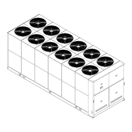
Ferroli RHA series Installation Manual (72 pages)
AIR COOLED WATER CHILLERS AND HEAT PUMPS WITH AXIAL FANS
Brand:
Ferroli
| Category:
Chiller
| Size: 3.18 MB
Table of Contents
Table of Contents
3
General Specifications
4
European Directives
4
Identification Plate of the Unit
4
Presentation of the Unit
5
Identification Code of the Unit
5
Description of the Components
6
Version with Desuperheater VD (Available for both IR Units and IP Units)
8
Accessories and Optional Equipment
9
Mechanical Accessories
9
Electrical Accessories
12
Mechanical Options
12
Electrical Options
12
General Technical Specification
13
General Technical Specifications
13
Nominal Performances
14
Standard Unit AB - MEDIUM TEMPERATURE PLANT - Data Certified by EUROVENT
14
Standard Unit AB - LOW TEMPERATURE PLANT
14
Standard Unit AB - MEDIUM TEMPERATURE PLANT - Data Declared According to UNI en 14511
15
Standard Unit AB - LOW TEMPERATURE PLANT - Data Declared According to UNI en 14511
15
Low Noise Unit as - MEDIUM TEMPERATURE PLANT - Data Certified by EUROVENT
16
Low Noise Unit as - LOW TEMPERATURE PLANT
16
Low Noise Unit as - MEDIUM TEMPERATURE PLANT - Data Declared According to UNI en 14511
17
Low Noise Unit as - LOW TEMPERATURE PLANT - Data Declared According to UNI en 14511
17
Extra Low Noise Unit AX - MEDIUM TEMPERATURE PLANT - Data Certified by EUROVENT
18
Extra Low Noise Unit AX - LOW TEMPERATURE PLANT
18
Extra Low Noise Unit AX - MEDIUM TEMPERATURE PLANT - Data Declared According to UNI en 14511
19
Extra Low Noise Unit AX - LOW TEMPERATURE PLANT - Data Declared According to UNI en 14511
19
Standard Performances - Ir Cooling Unit Only
20
Performances - Standard Unit AB
20
Performances - Low Noise Unit as
21
Performances - Extra Low Noise Unit AX
22
Standard Performances - Ip Heat Pump Units
23
Performances in Cooling Mode - Standard Unit AB
23
Performances in Heating Mode - Standard Unit AB
24
Performances in Cooling Mode - Low Noise Unit as
25
Performances in Heating Mode - Low Noise Unit as
26
Performances in Cooling Mode - Extra Low Noise Unit AX
27
Performances in Heating Mode - Extra Low Noise Unit AX
28
Correction Factor for the Use of Glycol
29
Correction Factor for the Use of Glycol in HEATING MODE
29
Correction Factor for the Use of Glycol in COOLING MODE
29
Fouling Factors
29
General Specifications - Brine Unit Br - Bp
30
Brine Unit (BR)
30
GENERAL SPECIFICATIONS - VERSION with DESUPERHEATER
31
(VD) Ir Cooling Unit Only
31
Acoustic Version: AB (Standard Unit)
31
Acoustic Version: as (Low Noise Unit)
31
Acoustic Version: AX (Extra Low Noise Unit)
31
Performances Version with Desuperheater (VD)
32
GENERAL SPECIFICATIONS - VERSION with DESUPERHEATER
33
(VD) Ip Heat Pump Unit
33
Acoustic Version: AB (Standard Unit)
33
Acoustic Version: as (Low Noise Unit)
33
Acoustic Version: AX (Extra Low Noise Unit)
33
Performances Version with Desuperheater (VD)
34
General Specifications - Full Heat Recovery Unit (Vr) Ip Heat Pump Unit
35
Acoustic Version: AB (Basic Unit)
35
Acoustic Version: as (Low Noise Unit)
35
Acoustic Version: AX (Extra Low Noise Unit)
35
Full Heat Recovery Unit Performances (VR)
36
Noise Levels
37
Standard Unit AB
37
Low Noise Unit as
37
Extra Low Moise Unit AX
37
Operating Range
38
Water PRESSURE DROP EVAPORATOR
39
Operating Range
39
Water PRESSURE DROP DESUPERHEATER
40
Operating Range
40
Working HEAD of the PUMPING MODULE MP am STD and MP SS STD
41
Operating Range
41
HIGH Working HEAD of the PUMPING MODULE MP am HP1 and MP SS HP1
42
Operating Range
42
Reception and Positioning
43
Inspections on Arrival
43
Safety Prescriptions
43
Handling
43
Storage
44
Packing Removing
44
Positioning
44
Dimensional Data
45
Overall Dimensions
45
Description of the Components
45
Minimum Space Required for Operation
46
Vibration-Damper Installation
46
Condensation
46
Area of Support
46
Weight During Transport
47
Weight During Operation
48
Hydraulic Connections
50
General Rules
50
Hydraulic Layout of the System
50
Precautions for the Winter
50
Basic Diagram Standard Unit VB [PLANT SIDE WATER CIRCUIT]
51
Basic Diagram for Units with Desuperheater [RECOVERY WATER CIRCUIT]
51
Air Vent and Water Drain
52
Piping Connection with Victaulic Couplings and Water Flow Switch
52
Valve Regulating Diagram Valve
52
Electrical Connections
54
General Rules
54
Structure of the Electric Panel
54
Composition of the System
54
Unit Layout
54
R410A Protection Devices
57
Serial Interface: Rs485 Modbus® Rtu
58
REFRIGERANT Flow DIAGRAM - STANDARD UNIT VB
61
Refrigerant Flow Diagram in Cooling Mode IR
61
Refrigerant Flow Diagram in Heating Mode IP
62
REFRIGERANT Flow DIAGRAM - DESUPERHEATERS UNIT VD
63
Refrigerant Flow Diagram in Cooling Mode IR
63
Refrigerant Flow Diagram in Heating Mode IP
64
Start-Up
65
General Rules
65
Maintenance
65
Routine Maintenance
65
General Considerations
67
Safety and Pollution
68
Refrigerant Safety Card
68
First Aid
70
Advertisement
Advertisement
Related Products
Ferroli RGA HE series
Ferroli RGA Series
Ferroli RGA ST
Ferroli RCA 60
Ferroli RCA 65
Ferroli RCA 130
Ferroli RCA Series
Ferroli RCA 195
Ferroli RCA 220
Ferroli RCA 270
Ferroli Categories
Boiler
Heat Pump
Water Heater
Air Conditioner
Burner
More Ferroli Manuals
Login
Sign In
OR
Sign in with Facebook
Sign in with Google
Upload manual
Upload from disk
Upload from URL