Barco NX-4 Installation Manual
Nx-series
Hide thumbs
Also See for NX-4:
- Brochure & specs (8 pages) ,
- Specifications (2 pages) ,
- Product specifications (2 pages)
Table of Contents
Advertisement
Quick Links
Advertisement
Table of Contents

Subscribe to Our Youtube Channel
Related Manuals for Barco NX-4

Summary of Contents for Barco NX-4
- Page 1 NX fixed Installation manual R59770279/00 16/06/2008...
- Page 2 Barco nv Media & Entertainment Division Noordlaan 5, B-8520 Kuurne Phone: +32 56.36.89.70 Fax: +32 56.36.883.86 E-mail: sales.events@barco.com Visit us at the web: www.barco.com Printed in Belgium...
- Page 3 The period of guarantee begins on the date of transfer of risks, in the case of special systems and software on the date of commissioning, at latest 30 days after the transfer of risks. In the event of justified notice of complaint, Barco can repair the fault or provide a replacement at its own discretion within an appropriate period.
-
Page 5: Table Of Contents
Dimensions of the NX-4 module ........ - Page 6 Table of contents R59770279 NX FIXED 16/06/2008...
-
Page 7: Safety
1. Safety 1. SAFETY About this chapter Read this chapter attentively. It contains important information to prevent personal injury while installing your NX fixed display. Furthermore, it includes several cautions to prevent damage to the NX fixed tile. Ensure that you understand and follow all safety guidelines, safety instructions and warnings mentioned in this chapter before installing the NX fixed display. -
Page 8: Safety Guidelines
Structural & mounting components should be kept dry, clean, lubricated (only if recommended), coated properly, and otherwise maintained in a manner consistent with part design. Barco products must be used in a manner consistent with their design and inspected on a routine basis for security, wear, deformation, corrosion and any other circumstances that may affect the load handling capability of the part. -
Page 9: Important Safety Instructions
1. Safety Important safety instructions Instructions: • Read these instructions. • Keep these instructions. • Heed all warnings. • Follow all instructions. • Clean only with materials or chemicals that are inert, nonabrasive, noncorrosive and non-marking. Consult the manufacturer for further advice should any doubts exist regarding any cleaning procedure. •... -
Page 10: Important Warnings
1. Safety Important warnings Important warnings: Risk of electric shock: Do not open. To reduce the risk of electric shock, do not remove cover (or back). No user-serviceable parts inside. Refer servicing to qualified service personnel. Maximum and minimum ambient temperature: The maximum ambient temperature for the LED wall is 40 °C, the minimum temperature is 0 °C. -
Page 11: Proper Usage
• Only Barco cables specified to be used with the NX display are to be used to connect components in an NX wall. Further, care must be taken to connect signal only according to the installation manual. - Page 12 1. Safety R59770279 NX FIXED 16/06/2008...
-
Page 13: Installation Requirements
2. Installation requirements 2. INSTALLATION REQUIREMENTS About this chapter This chapter enumerates the mechanical requirements for the NX fixed display, the electrical requirements to power up the NX fixed display and the system requirements to run the control software efficiently. ARNING The NX display is an indoor product. -
Page 14: Mechanical Requirements Of A Suspended Installation
2. Installation requirements Mechanical requirements of a suspended installation Weight Do not underestimate the weight of a complete NX fixed display. Be sure that the truss installation on which the NX fixed display has to be installed is capable of handling five (5) times the complete load of the display. Note that one NX fixed tile weighs approximately 14 kg (or 72 kg per square meter display). - Page 15 Truss beam that supports the sliding system. ARNING Barco suggests to use a level system as mentioned below to obtain a horizontal surface that answers to the flatness tolerance of 0,1 mm. Use both bolts to horizontally align all NX high precision frames.
- Page 16 2. Installation requirements Consult Barco for advice or more information about preparing a truss beam. R59770279 NX FIXED 16/06/2008...
-
Page 17: Mechanical Requirements Of A Standing Installation
2. Installation requirements Mechanical requirements of a standing installation Weight Do not underestimate the weight of a complete NX fixed display. Be sure that the floor installation on which the NX fixed display has to be installed is capable of handling five (5) times the complete load of the display. Note that one NX fixed tile weighs approximately 14 kg (or 72 kg per square meter display). - Page 18 Tolerances 0.1 mm Image 2-5 High precision frame. Sliding system using vertical and horizontal adjustable block. Rail system with a flatness tolerance of 0,1 mm. Consult Barco for advice or more information about preparing a floor installation. R59770279 NX FIXED 16/06/2008...
-
Page 19: Safety Requirements For The Nx Fixed Display
A NX fixed display is limited to a height of 50 NX fixed tiles and the display surface has to obtain a flatness within a tolerance zone of 1 degree with a surface perpendicular to the reference surface (ceiling or floor). Barco suggests to use an adjustable system as illustrated below. Tolerance 90 1 Image 2-7 Example for a trussed installation. - Page 20 2. Installation requirements Example of a trussed installation that needs to be secured (10 x 10 tiles) CEILING CEILING 5 tiles 5 tiles Image 2-8 R59770279 NX FIXED 16/06/2008...
- Page 21 2. Installation requirements Example of a standing installation that needs to be secured (19 x 10 tiles) WALL Image 2-9 R59770279 NX FIXED 16/06/2008...
-
Page 22: Electrical Requirements For The Nx Fixed Display
. Every power source cable should be protected by a circuit breaker or fuses rated 16 A / 250 VAC (15 A / 250 VAC in the USA and Canada). Barco provides a range of power boxes, which meet the requirements of your NX display. Contact Barco for more information about power boxes and power requirements for your NX display. -
Page 23: System Requirements For The Control Software
SXGA resolution (1280 x 1024) with 32 Mb video memory Serial communication port Ethernet connection • Software Windows XP Professional or Windows Vista 1. It runs on Windows 2000 but when problems are discovered, Barco does not deliver any support R59770279 NX FIXED 16/06/2008... - Page 24 2. Installation requirements R59770279 NX FIXED 16/06/2008...
-
Page 25: System Overview
3. System overview 3. SYSTEM OVERVIEW About this chapter This chapter enumerates the fundamental elements of the NX fixed display. Overview • Introduction • Order Info R59770279 NX FIXED 16/06/2008... -
Page 26: Introduction
3. System overview Introduction The fundamental elements of an NX fixed display system are: • NX modules. • NX precision frames. • NX power box. • DX-700 digitizer. • Control software “Director toolset”. Block diagram NX fixed display system: control tile tile tile... -
Page 27: Order Info
3. System overview Order Info Example A: 1 NX fixed tile Article number Description Quantity R9851268 NX fixed precision frame R9851267 NX fixed cable kit R9854610 NX controller (1 piece) R9854631 NX module (1 piece) Example B: 9 NX fixed tiles Article number Description Quantity... - Page 28 3. System overview R59770279 NX FIXED 16/06/2008...
-
Page 29: Components Of A Nx Fixed Tile
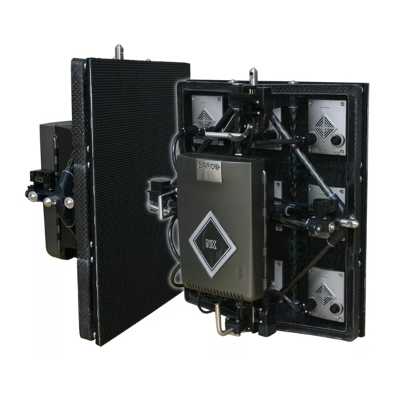
4. Components of a NX fixed tile 4. COMPONENTS OF A NX FIXED TILE General introduction The NX fixed tile consists in a high precision framework on which nine NX modules fit. On the rear side of the framework fits the NX control box, which is electrical connected with these nine NX modules. -
Page 30: Nx Precision Frame
Slot for assembly nut (each corner has 2 slots). AUTION NX precision frames are only to be used in conjunction with Barco NX module assemblies. Recognizing the top side of the NX precision frame It is important that you recognize the front and top side of the NX precision frames, because during installation you have to be sure that the top side of each precision frame is facing upwards. - Page 31 4. Components of a NX fixed tile Image 4-4 R59770279 NX FIXED 16/06/2008...
-
Page 32: Nx Module
One tile covers 3 x 3 NX modules and one NX-4 module has an LED grid of 32 pixels wide by 36 pixels high. So, an NX-4 display of 10 tiles high and 20 tiles wide has a native HD resolution of 1920 pixels x 1080 pixels. Note that the NX-6 module has an LED grid of 24 pixels wide by 27 pixels high. - Page 33 4. Components of a NX fixed tile Image 4-6 Image 4-7 NX module - module interconnection cable. NX control box - module interconnection cable. R59770279 NX FIXED 16/06/2008...
-
Page 34: Nx Control Box
4. Components of a NX fixed tile NX control box Introduction NX control box The small design and its synthetic housing make of the NX control box a lightweight device. The NX control box contains a power supply unit and a controller/re-sync unit. Thanks to the integrated mounting plate, the NX control box can easily be attached to the rear framework of the NX frame. - Page 35 Barco uses HDMI connectors and cables, which allows a higher bandwidth for data communica- tion between the NX control boxes and DX-700 digitizer. Nevertheless, Barco does not use the standard HDMI protocol but their own communication protocol NNI (New Netebuk Interface). As a result the pin configuration of the HDMI connector is different as well.
-
Page 36: Nx Fixed Tile Inner Cabling
4. Components of a NX fixed tile NX fixed tile inner cabling NX fixed tile inner HDMI cabling While configuring the NX fixed display with the Director toolset, the DX-700 digitizer will scan all connected tiles of the installed LED-wall and automatically assign a logical address number to each tile. The address number is independable of the location of the NX tile in the LED-wall. - Page 37 4. Components of a NX fixed tile ....Image 4-12 ARNING Risk of electric shock / Risk of fire: To protect against risk of fire caused by overloading of power cables, MAXIMUM eight (8) tiles may be con- nected in parallel.
- Page 38 4. Components of a NX fixed tile Image 4-13 R59770279 NX FIXED 16/06/2008...
-
Page 39: Nx Fixed Peripherals And Accessories
5. NX fixed peripherals and accessories 5. NX FIXED PERIPHERALS AND ACCESSORIES About this chapter This chapter describes, or refers to another manual, all the peripherals and accessories, which can be used in the setup of an NX fixed display. Overview •... -
Page 40: Dx-700 Digitizer
• Next generation LED products such as the NX-4 tiles are supported via the NNI interface on the system’s NNI Output Module. Image processing and LED wall configuration and control functions are adjusted from Barco’s Director toolset, or via controls on the DX-700 digitizer front panel itself. -
Page 41: Power Boxes
To ensure safe and reliable operation of the NX fixed display, a suitable system for AC power distribution must be used. Though 3 party solutions may be used, several sizes and types of power distributions are available from Barco. For smaller system the “Mono Phase Power Box”... -
Page 42: Control Software
General The control software is designed as a graphic user interface (GUI) and can be used to control and configure the digitizer as well as the Barco LED wall via a PC (e.g. Director toolset). Minimum required software version: 1.06 Image 5-4 Control software “Director toolset”. -
Page 43: Setup Process Of A Nx Fixed Display
6. Setup process of a NX fixed display 6. SETUP PROCESS OF A NX FIXED DISPLAY About this chapter This chapter roughly describes the installation process of the NX fixed display for a standing installation or trussed configuration. Several process stages refer to one or more of the detailed "Basic procedures", see "Basic procedures for a front access NX fixed display", page 45 and see "Basic procedures for a back access NX fixed display", page 53 ARNING Safety first. -
Page 44: Setup Process Of A Suspended Installation
Contact Barco for more information on the illustrated systems. This chapter explains how to install a suspended NX fixed display and assumes the truss beam has been installed and answers to the flatness requirements, see chapter "2. - Page 45 6. Setup process of a NX fixed display Image 6-2 3. Attach the necessary securing points, see "Safety requirements for the NX fixed display", page 15, and level out the NX fixed display surface as mentioned. 4. Continue building the NX fixed display by connecting the NX fixed tiles one after another. Caution: Pay attention to the safety requirements and secure the NX fixed display every five (5) tiles.
- Page 46 6. Setup process of a NX fixed display Image 6-3 5. Secure the corner tiles at the bottom of the display and every outside tile at each fifth horizontal row, see "Safety requirements for the NX fixed display", page 15. R59770279 NX FIXED 16/06/2008...
-
Page 47: Setup Process Of A Standing Installation
6. Setup process of a NX fixed display Setup process of a standing installation ARNING A NX fixed display is limited to a height of 50 NX fixed tiles and the display surface has to obtain a flatness within a tolerance zone of 1 degree with a surface perpendicular to the reference surface (ceiling). This chapter explains how to install a standing NX fixed display and assumes the floor installation has been installed and answers to the flatness requirements, see "Mechanical requirements of a standing installation", page 13... - Page 48 6. Setup process of a NX fixed display Image 6-5 3. Attach the necessary securing points, see "Safety requirements for the NX fixed display", page 15, and level out the NX fixed display surface as mentioned. 4. Continue building the NX fixed display by connecting the NX fixed tiles one after another. Caution: Pay attention to the safety requirements and secure the NX fixed display every five (5) tiles.
-
Page 49: Basic Procedures For A Front Access Nx Fixed Display
7. Basic procedures for a front access NX fixed display 7. BASIC PROCEDURES FOR A FRONT ACCESS NX FIXED DISPLAY About this chapter This chapter contains all installation procedures necessary to handle the NX tiles, to set up an NX fixed front access display. These procedures chronologically describe, with detailed step by step actions and illustrations, how to install an NX fixed display in a floor mount or hanging configuration. -
Page 50: Connecting Nx High Precision Frames
7. Basic procedures for a front access NX fixed display Connecting NX high precision frames Necessary tools • 5 mm Allen wrench. • 8 mm Allen wrench. • Laser level. Necessary parts • 2 hexagon socket bolts, M8 x 20, 17379, reference A (B360903). •... - Page 51 7. Basic procedures for a front access NX fixed display Image 7-3 3. Repeat step 1 — 2 until all frames are connected. 4. Secure the frames if needed, see "Safety requirements for the NX fixed display", page 15 and level out the whole framework using a laser level.
-
Page 52: Mounting A Nx Control Box
7. Basic procedures for a front access NX fixed display Mounting a NX control box Necessary parts • NX control box. • Safety cable (R857753). How to mount a NX control box 1. Position the NX control box in front of the high precision frame and secure the NX control box to the frame using the safety cable. Image 7-4 R857753. - Page 53 7. Basic procedures for a front access NX fixed display Image 7-7 5. Repeat step 1 — 4 until all NX fixed tiles are provided with a NX control box. R59770279 NX FIXED 16/06/2008...
-
Page 54: Power And Data Cabling
7. Basic procedures for a front access NX fixed display Power and data cabling How to connect the power an data cables? 1. see chapter "4. Components of a NX fixed tile", "NX fixed tile inner cabling", page 32, on how to connect the NX fixed tiles. ARNING Pay attention to the orientation of the illustrations mentioned in the indicated chapter. -
Page 55: Mounting Nx Modules
7. Basic procedures for a front access NX fixed display Mounting NX modules Necessary parts • 9 NX-4 or NX-6 tiles. • 6 cables (Z3499818). • 3 cables (Z3499819). Procedure Always mount the tiles starting from the right top corner, working your way down to the left bottom corner. - Page 56 7. Basic procedures for a front access NX fixed display Poort 2 Poort 3 Image 7-10 3. Repeat step 1 — 2 until all NX fixed tiles are provided with NX modules. Note: Note that for each row, the last out port is not used. Image 7-11 R59770279 NX FIXED 16/06/2008...
-
Page 57: Basic Procedures For A Back Access Nx Fixed Display
8. Basic procedures for a back access NX fixed display 8. BASIC PROCEDURES FOR A BACK ACCESS NX FIXED DISPLAY About this chapter This chapter contains all installation procedures necessary to handle the NX tiles, to set up an NX fixed back access display. These procedures chronologically describe, with detailed step by step actions and illustrations, how to install an NX fixed display in a floor mount or hanging configuration. -
Page 58: Connecting Nx High Precision Frames
8. Basic procedures for a back access NX fixed display Connecting NX high precision frames Necessary tools • 5 mm Allen wrench. • 8 mm Allen wrench. • Laser level. Necessary parts • 2 hexagon socket bolts, M8 x 20, 17379, reference A (B360903). •... - Page 59 8. Basic procedures for a back access NX fixed display Image 8-3 3. Repeat step 1 — 2 until all frames are connected. 4. Secure the frames if needed, see "Safety requirements for the NX fixed display", page 15 and level out the whole framework using a laser level.
-
Page 60: Mounting Nx Modules
8. Basic procedures for a back access NX fixed display Mounting NX modules Necessary tools Module safety cable (R9853390). Necessary parts • 9 NX-4 or NX-6 tiles. • 6 cables (Z3499818). • 3 cables (Z3499819). Procedure Always mount the tiles starting from the right top corner, working your way down to the left bottom corner. - Page 61 8. Basic procedures for a back access NX fixed display Image 8-6 2. Assemble all tiles according to the procedure mentioned above. Image 8-7 3. Connect the cables as illustrated. Tip: Position the 3 large cables (Z3499819) is such a way that the distinction between Port 1, Port 1 and Port 3 is obvious. R59770279 NX FIXED 16/06/2008...
- Page 62 8. Basic procedures for a back access NX fixed display Image 8-8 R59770279 NX FIXED 16/06/2008...
-
Page 63: Mounting A Nx Control Box
8. Basic procedures for a back access NX fixed display Mounting a NX control box Necessary parts • NX control box. • Safety cable (R857753). How to mount a NX control box? 1. Position the NX control box in front of the high precision frame and secure the NX control box to the frame using the safety cable. Image 8-9 R857753. - Page 64 8. Basic procedures for a back access NX fixed display Image 8-12 Front view. 5. Repeat step 1 — 3 until all NX fixed tiles are provided with a NX control box. R59770279 NX FIXED 16/06/2008...
-
Page 65: Power And Data Cabling
8. Basic procedures for a back access NX fixed display Power and data cabling How to connect the power an data cables? 1. see chapter "4. Components of a NX fixed tile", "NX fixed tile inner cabling", page 32, on how to connect the NX fixed tiles. ARNING Pay attention to the orientation of the illustrations mentioned in the indicated chapter. - Page 66 8. Basic procedures for a back access NX fixed display R59770279 NX FIXED 16/06/2008...
-
Page 67: Maintenance
9. Maintenance 9. MAINTENANCE Overview • Cleaning NX fixed tiles R59770279 NX FIXED 16/06/2008... -
Page 68: Cleaning Nx Fixed Tiles
9. Maintenance Cleaning NX fixed tiles ARNING ISOPROPANOL ALCOHOL (200–661–7). Hazardous product. Irritating to eyes and skin. Always use in a well ventilated area. Vapors may cause drowsi- ness and dizziness. Avoid contact with skin and eyes. In case of contact with the eyes, rinse immediately with plenty of water and seek medical advise. -
Page 69: Servicing
10. SERVICING 10. SERVICING Overview • Safety instructions • NX control box diagnostic • NX module diagnostic • Removing a NX module through front access • Removing a NX module through back access • Removing a NX control box through front access •... -
Page 70: Safety Instructions
Inspect the complete LED-wall for security, wear, deformation, corrosion, and any other circumstances that may affect the load handling capability of the part. • Do not modify and/or replicate any component. Barco uses specific materials and manufacturing processes in order to achieve part strength. No other parts than Barco parts are allowed. •... -
Page 71: Nx Control Box Diagnostic
10. SERVICING 10.2 NX control box diagnostic Status LED’s of the NX control box The NX control box is provided with four status LED’s. One green, one orange, one yellow and one red. The four status LED’s are located at the front of the NX control box. The green LED indicates the status of the power. The orange LED indicates the communication status of the NX module. - Page 72 10. SERVICING Diagnostic Action Status Situation Orange Communication with neighboring control box(es) or digitizer is OK (matches configuration). Flashing Neighboring communication does • Check the cabling with the neighboring not match configuration. Expected control boxes or digitizer. communication is not established. •...
-
Page 73: Nx Module Diagnostic
10. SERVICING 10.3 NX module diagnostic Status LED’s of the NX module The NX module is provided with four status LED’s. One green, one orange, one yellow and one red. The four status LED’s are located as two pairs below the input and output ports of the NX module. The green LED indicates the status of the power. The orange LED indicates the status of the software and microprocessor. - Page 74 10. SERVICING Diagnostic Action Status Situation Yellow Flashing fast NX module runs in BOOT mode Replace the NX module. Flashing 3 times + NX module runs with backup software and • Try to reload the latest version of the pause backup firmware.
-
Page 75: Removing A Nx Module Through Front Access
10. SERVICING 10.4 Removing a NX module through front access AUTION The following procedure must be performed by authorized and qualified technical personnel only, which are thoroughly familiar with the product and all of the proper safety checks of this product. To do otherwise increases the risk of hazard and injury to the user. - Page 76 10. SERVICING 5. Insert one NX module removal tool above and one NX module removal tool below the NX module, which you want to remove, as illustrated. Make sure that the tabs of the removal tool are facing the NX module which you want to remove. Caution: Make sure that the NX display is powerless while using the NX module removal tool.
- Page 77 10. SERVICING Image 10-8 R59770279 NX FIXED 16/06/2008...
-
Page 78: Removing A Nx Module Through Back Access
10. SERVICING 10.5 Removing a NX module through back access AUTION The following procedure must be performed by authorized and qualified technical personnel only, which are thoroughly familiar with the product and all of the proper safety checks of this product. To do otherwise increases the risk of hazard and injury to the user. - Page 79 10. SERVICING Image 10-11 5. Rotate the NX module 45° and pull the NX module gently diagonally back through the opening. Caution: Be careful not to damage the shaders or LEDs of the NX module while removing the NX module. Image 10-12 R59770279 NX FIXED 16/06/2008...
-
Page 80: Removing A Nx Control Box Through Front Access
10. SERVICING 10.6 Removing a NX control box through front access How to remove a NX control box? 1. Remove the 3 center NX modules, see chapter "10. SERVICING", "Removing a NX module through front access", page 71 Image 10-13 2. - Page 81 10. SERVICING Image 10-15 5. Remove the safety cable. Image 10-16 R59770279 NX FIXED 16/06/2008...
-
Page 82: Removing A Nx Control Box Back Access
10. SERVICING 10.7 Removing a NX control box back access How to remove a NX control box? 1. Loosen the fast screw and slide the NX control box out of its position. Image 10-17 2. Disconnect all cables. 3. Remove the safety cable. Image 10-18 R59770279 NX FIXED 16/06/2008... -
Page 83: Removing Shaders From An Nx Module
10. SERVICING 10.8 Removing shaders from an NX module The NX-4 module contains a matrix of 4 x 4 shaders. To remove the shaders from the NX module you have to remove the NX module from the tile first. Necessary tools NX shader removal fork. - Page 84 10. SERVICING Image 10-21 AUTION Do not reuse removed shaders. Always replace with new shaders. R59770279 NX FIXED 16/06/2008...
-
Page 85: Installing The Shaders On An Nx Module
10. SERVICING 10.9 Installing the shaders on an NX module Necessary parts New shaders. How to install the shaders on an NX module? 1. Softly press the new shader over the LED’s. Use your bare fingers (not nails) to press the shader over the LED’s. Make sure that the shaders are correctly oriented. - Page 86 10. SERVICING R59770279 NX FIXED 16/06/2008...
-
Page 87: Dimensions
A. DIMENSIONS Overview • Dimensions of the NX fixed tile • Dimensions of the NX high precision frame • Dimensions of the NX-4 module • Dimensions of the NX-6 module • Dimensions of the NX control box R59770279 NX FIXED 16/06/2008... -
Page 88: Dimensions Of The Nx Fixed Tile
A. Dimensions A.1 Dimensions of the NX fixed tile Dimensions NX fixed tile Image A-1 R59770279 NX FIXED 16/06/2008... -
Page 89: Dimensions Of The Nx High Precision Frame
A. Dimensions A.2 Dimensions of the NX high precision frame Dimensions high precision frame Image A-2 R59770279 NX FIXED 16/06/2008... -
Page 90: Dimensions Of The Nx-4 Module
A. Dimensions A.3 Dimensions of the NX-4 module Dimensions NX-4 module 149,03 15,6 121,5 Image A-3 Dimensions given in millimeters. R59770279 NX FIXED 16/06/2008... -
Page 91: Dimensions Of The Nx-6 Module
A. Dimensions A.4 Dimensions of the NX-6 module Dimensions NX-6 module 149,03 15,41 121,5 Image A-4 Dimensions given in millimeters. R59770279 NX FIXED 16/06/2008... -
Page 92: Dimensions Of The Nx Control Box
A. Dimensions A.5 Dimensions of the NX control box Dimensions NX control box 110 mm 184 mm 273 mm 185 mm 190,6 mm 230 mm Image A-5 R59770279 NX FIXED 16/06/2008... - Page 93 Revision Sheet Barco nv Media & Entertainment Division/Documentation Noordlaan 5, B-8520 Kuurne Phone: +32 56.36.89.70, Fax: +32 56.36.88.24 E-mail: service.mne@barco.com, Web: www.barco.com From: Date: Please correct the following points in this documentation (R59770279/00): page wrong correct R59770279 NX 16/06/2008 FIXED...
Need help?
Do you have a question about the NX-4 and is the answer not in the manual?
Questions and answers