Advertisement
Table of Contents
- 1 Important Safeguards
- 2 Housing Installation, Ceiling, Wall and End Mount
- 3 Power Tray Installation, Ceiling, Wall and End Mount
- 4 Trim Installation, Ceiling, Wall and End Mount
- 5 Exit Panel Installation, Wall and End Mount Only
- 6 Operation
- 7 Maintenance
- 8 Troubleshooting Guide
- Download this manual
SURE-LITES
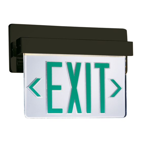
Installation Instructions - ELX Series L.E.D. Edge Lit Exit Signs
For AC and Self Powered, Rough-In Housings, Power Trays and Trim Sections
IMPORTANT SAFEGUARDS
WHEN USING ELECTRICAL EQUIPMENT, BASIC SAFETY PRECAUTIONS
SHOULD ALWAYS BE FOLLOWED INCLUDING THE FOLLOWING:
READ AND FOLLOW ALL SAFETY INSTRUCTIONS.
1.
2. Do not use outdoors.
3. Do not let power supply cords touch hot surfaces.
4. Do not mount near gas or electric heaters.
5. Equipment should be mounted in locations and at heights where it will not readily be subjected to
tampering by unauthorized personnel.
6. The use of accessory equipment not recommended by Sure-Lites may cause an unsafe condition.
7. Do not use this equipment for other than its intended purpose.
8. Disconnect power when installing or servicing this equipment.
SAVE THESE INSTRUCTIONS.
9.
HOUSING INSTALLATION, CEILING, WALL AND END MOUNT
Step 1. Remove appropriate side or back knock-out in housing.
Step 2. Affix bar hanger assembly to housing. Bar hangers are adjustable from 14" to 24". If desired
brackets may be placed on short sides of the housing.
Step 3. Extend bar hangers to fit between joists. (Figure 1) Position fixture temporarily by hammering nail-in
tabs into studs. Secure permanently into studs with appropriate fastener (not included).
Step 4. Adjust fixture for suitable ceiling or wall thickness by loosening hex screws inside of housing.
Position the edge of the housing to be level with the ceiling or wall line. Tighten hex screws to lock
fixture in position.
Step 5. Extend unswitched 24 hour AC supply of rated voltage to EXIT housing. Circuit should not be
energized at this time.
Step 6. Connect power supply and ground in accordance with local codes. Wire connections as follows:
277V line to Orange lead; 120V line to Black lead; Neutral to white lead. Ground to green lead; Cap unused line lead.
POWER TRAY INSTALLATION, CEILING, WALL AND END MOUNT
CAUTION: Check your correlation labels before making any connections. ELE-6XX & ELE-7XX LED series power trays are intended for use with
UH-LED series housings and TC-6XX, TC-7XX, TW-6XX, TW-7XX, TE-6XX, & TE-7XX-LED series trims only.
Plug nine position connector into corresponding connector in housing (Figure 2), install power tray and tighten mounting
Step 1.
screw. Proceed with Trim Installation.
CEILING
MOUNT
UNITS
Figure 2
WALL
MOUNT
UNITS
2-POSITION
LED DISPLAY
CONNECTOR
SURE-LITES
Customer First Center 1121 Highway 74 South Peachtree City, GA 30269
9-POSITION
CONNECTOR
4-POSITION
TEST SWITCH PC
BOARD CONNECTOR
(SELF POWERED
UNITS ONLY)
Figure 1
END
MOUNT
UNITS
1/07
049-144B
Advertisement
Table of Contents

Subscribe to Our Youtube Channel
Related Manuals for Cooper Lighting ELX Series


Summary of Contents for Cooper Lighting ELX Series
-
Page 1: Important Safeguards
SURE-LITES Installation Instructions - ELX Series L.E.D. Edge Lit Exit Signs For AC and Self Powered, Rough-In Housings, Power Trays and Trim Sections IMPORTANT SAFEGUARDS WHEN USING ELECTRICAL EQUIPMENT, BASIC SAFETY PRECAUTIONS SHOULD ALWAYS BE FOLLOWED INCLUDING THE FOLLOWING: READ AND FOLLOW ALL SAFETY INSTRUCTIONS. - Page 2 These instructions do not claim to cover all details or variations in the equipment, procedure or process described, nor to provide directions for meeting every possible contingency during installation, operation or maintenance. When additional information is desired to satisfy a problem not covered sufficiently for users purpose, please contact your Cooper Lighting representative. SURE-LITES...
Need help?
Do you have a question about the ELX Series and is the answer not in the manual?
Questions and answers