Table of Contents
Advertisement
Quick Links
Copyright Eurotherm Drives Limited 2000
All rights strictly reserved. No part of this document may be stored in a retrieval system, or transmitted in any form or by any means to persons not
employed by a Eurotherm group company without written permission from Eurotherm Drives Ltd.
Although every effort has been taken to ensure the accuracy of this document it may be necessary, without notice, to make amendments or correct
omissions. Eurotherm Drives cannot accept responsibility for damage, injury, or expenses resulting therefrom.
Printed in England
This manual was downloaded on www.sdsdrives.com
+44 (0)117 938 1800 - info@sdsdrives.com
COMPATIBLE WITH VERSION 6 SOFTWARE
EUROTHERM
584S Frequency
Inverter
Product Manual
HA389756
DRIVES
Issue 7
Advertisement
Chapters
Table of Contents

Related Manuals for Eurotherm Drives 584S


Summary of Contents for Eurotherm Drives 584S
- Page 1 All rights strictly reserved. No part of this document may be stored in a retrieval system, or transmitted in any form or by any means to persons not employed by a Eurotherm group company without written permission from Eurotherm Drives Ltd.
- Page 2 Eurotherm Drives warrants the goods against defects in design, materials and workmanship for the period of 12 months from the date of delivery on the terms detailed in Eurotherm Drives Standard Conditions of Sale IA058393C. Eurotherm Drives reserves the right to change the content and product specification without notice.
- Page 3 This manual is to be made available to all persons who are required to design an application, install, service or come into direct contact with the product. APPLICATIONS ADVICE: Applications advice and training is available from Eurotherm Drives Ltd.
- Page 4 APPLICATION RISK: The integration of this product into other apparatus or system is not the responsibility of Eurotherm Drives Ltd as to its applicability, effectiveness or safety of operation or of other apparatus or systems.
- Page 5 How to Use this Manual This manual provides information to support the installation and operation of the 584S Frequency Inverter. A description of each of the chapters is given here to assist in locating and using the information contained within the manual.
-
Page 6: Table Of Contents
POWER ON....................4-8 SETUP PARAMETERS ................. 4-9 PASSWORD.................... 4-31 PARAMETERS SAVE ................. 4-32 SYSTEM ....................4-32 SERIAL LINK.................... 4-34 MENUS ....................4-38 Chapter 5 DIAGNOSTICS AND FAULT FINDING INTRODUCTION ..................5-1 DIAGNOSTICS ..................5-1 ALARMS ....................5-5 584S Frequency Inverter Cont.1... - Page 7 APPENDIX B - SERIAL COMMUNICATIONS OPTION ......... 8-6 APPENDIX C - PARAMETER LANGUAGE ..........8-34 APPENDIX D - PARABOLIC RAMP TIMES ..........8-45 APPENDIX E - S RAMP TIMES..............8-48 APPENDIX F - 584S TYPE 7 MECHANICAL OUTLINE DRAWINGS..... 8-51 584S Frequency Inverter Cont.2...
- Page 8 Electrical Ratings - Power Circuit ( Quadratic torque ) ..... 1-5 Electrical Ratings - Control Circuit .......... 1-6 Mechanical Details..............1-7 584S ( TYPE 4 ) ..............1-7 584S ( TYPE 5 ) ..............1-7 584S ( TYPE 6 ) ..............1-8 584S ( TYPE 7 ) ..............
-
Page 9: Chapter 1 Product Overview
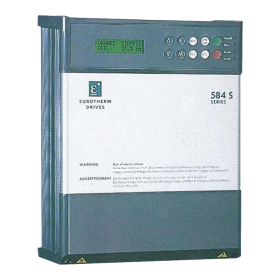
45.0 - 75.0kW 55 - 90kW The 584S models are housed in chassis of similar appearance, refer to Figure 1.1. The chassis size increases with power rating. The models are further identified by the product code, refer to "PRODUCT CODE" in this chapter. -
Page 10: Component Identification
Chapter 1 - Product Overview COMPONENT IDENTIFICATION This manual refers to various connector terminals within the equipment which are accessible to the user for installation purposes. A diagram of a 584S Frequency Inverter is given in Figure 1.1. Item Description... -
Page 11: Technical Specification
+44 (0)117 938 1800 - info@sdsdrives.com Chapter 1 - Product Overview TECHNICAL SPECIFICATION The following paragraphs provide technical information regarding the features and performance characteristics of the 584S Frequency Inverters. General Control: Full control via the MMI display menus and external analogue and digital control inputs. -
Page 12: Electrical Ratings - Power Circuit ( Constant Torque )
Note :- For installations requiring UL compliance, short circuit protection Semiconductor Fuses should be installed in the 3-phase supply to the 584S products. These fuses are suitable for branch circuit short-circuit protection of the solid-state motor controllers only. For installations NOT requiring UL compliance, use class"T" fuses or a circuit breaker. -
Page 13: Electrical Ratings - Power Circuit ( Quadratic Torque )
Note :- For installations requiring UL compliance, short circuit protection Semiconductor Fuses should be installed in the 3-phase supply to the 584S products. These fuses are suitable for branch circuit short-circuit protection of the solid-state motor controllers only. For installations NOT requiring UL compliance, use class"T" fuses or a circuit breaker. -
Page 14: Electrical Ratings - Control Circuit
This manual was downloaded on www.sdsdrives.com +44 (0)117 938 1800 - info@sdsdrives.com Chapter 1 - Product Overview Electrical Ratings - Control Circuit The following ratings relate to 584S products. Supplies Reference Supplies ( for all analogue inputs ) +10V ± 0.1V, 10mA max - 10V ±... -
Page 15: Mechanical Details
This manual was downloaded on www.sdsdrives.com +44 (0)117 938 1800 - info@sdsdrives.com Chapter 1 - Product Overview Mechanical Details 584S ( TYPE 4 ) 584S ( TYPE 4 ) 584S ( TYPE 4 ) 584S ( TYPE 4 ) AIR FLOW CLEARANCE Refer to figure 3.1... -
Page 16: Type 6 )
This manual was downloaded on www.sdsdrives.com +44 (0)117 938 1800 - info@sdsdrives.com Chapter 1 - Product Overview 584S ( TYPE 6 ) 584S ( TYPE 6 ) 584S ( TYPE 6 ) 584S ( TYPE 6 ) AIR FLOW CLEARANCE Refer to figure 3.1... -
Page 17: Type 7 )
This manual was downloaded on www.sdsdrives.com +44 (0)117 938 1800 - info@sdsdrives.com Chapter 1 - Product Overview 584S ( TYPE 7 ) 584S ( TYPE 7 ) 584S ( TYPE 7 ) 584S ( TYPE 7 ) AIR FLOW CLEARANCE Refer to figure 3.1... -
Page 18: Special Considerations For Installations Requiring Compliance With Ul Standards
600Vac as appropriate (depending on the rated input voltage of the drive), must be installed upstream of the drive. For fuse current ratings, see Chapter 1 “Electrical Ratings - Power Circuit”. Model 584S Type 5 and 6 Series UL Recognized Component (JFHR2) semiconductor fuses must be installed upstream of the drive. For fuse current ratings, see Chapter 1 “Electrical Ratings - Power Circuit”. -
Page 19: Environmental Requirements
For operating ambient temperature range, see Chapter 1 “Electrical Ratings - Power Circuit”. Environmental Rating Model 584S Type 4, 5, 6, 7 Series with a product code block IV designation xx2x are suitable for direct wall mounting applications as they have a “Type 1 enclosure” rating. -
Page 20: Product Code
PRODUCT CODE All 584S units are fully identified using an eleven block alphanumeric code. This code details the drive calibration and settings on despatch from the factory. The product code appears as the "Model No." on the rating label at the side of the unit. - Page 21 Description XXXX Four digits specifying the mechanical package including livery and mechanical package style: First two digits Livery Standard Eurotherm Drives livery 01-99 Defined customer liveries Third digit Mechanical packaging style Standard (IP20), protected panel mounting IP20 and falling dirt protection, (UL Type 1) with...
-
Page 22: Example Codes
Brake Option None 584S/0750/400/0010/UK/ENG/E100/000/00/ Block 10 Aux Supply None 584S/0750/400/0010/UK/ENG/E100/000/00/000/ Block 11 Special options None 584S/0740/400/0010/UK/ENG/E100/000/00/000/000 Full Product Code - 584S/0750/400/0010/UK/ENG/E100/000/00/000/000 Quadratic Rating Quadratic Rating Quadratic Rating Quadratic Rating Block 1 Generic product 584S 584S/ Block 2 Required power 11kW *... - Page 23 Parameters ..............2-1 Diagnostics ..............2-1 Analogue Inputs/Outputs..........2-2 Digital Inputs/Outputs ............2-2 BASIC WIRING DIAGRAMS ............2-6 584S Type 4 ................. 2-6 584S Type 5 ................. 2-7 584S Type 6 ................. 2-8 584S Type 7 ................. 2-9 TERMINAL DESCRIPTIONS ............2-10 Power Terminals ..............
-
Page 24: Chapter 2 Pre-Installation Planning
(MMI) allows access to various options and adjustable parameters. A simplified block diagram of a 584S is presented in Figure 2.1. This shows the basic internal arrangement of the drive with the circuitry split between the control circuits, and the power circuits. The functions of the control circuits are further expanded in Figure 2.2. -
Page 25: Analogue Inputs/Outputs
CIRCUITS SUPPLY BRIDGE OUTPUTS M3/W INTERNAL DC LINK CHOKE EXTERNAL BRAKE RESISTOR DBR1 DYNAMIC BRAKE UNIT THIS CONNECTION IS MADE WHEN INTERNAL DYNAMIC BRAKING OPTION IS NOT FITTED Figure 2.1A - Simplified Block Diagram (584S Type 4) 584S Frequency Inverter... - Page 26 EXTERNAL BRAKE RESISTOR DBR1 DYNAMIC BRAKE UNIT THIS CONNECTION IS MADE WHEN INTERNAL DYNAMIC BRAKING OPTION IS NOT FITTED Figure 2.1B - Simplified Block Diagram (584S Type 5) SPEED FEEDBACK OPTION SERIAL LINK OPTION CONTROL INPUTS & OUTPUTS CONTROL CIRCUITS &...
- Page 27 OUTPUTS SUPPLY BRIDGE M3/W INTERNAL DC LINK CHOKE DBR2 EXTERNAL BRAKE RESISTOR DBR1 DYNAMIC BRAKE UNIT THIS CONNECTION IS MADE WHEN INTERNAL DYNAMIC BRAKING OPTION IS NOT FITTED Figure 2.1D - Simplified Block Diagram (584S Type 7) 584S Frequency Inverter...
- Page 28 This manual was downloaded on www.sdsdrives.com +44 (0)117 938 1800 - info@sdsdrives.com Chapter 2 - PRE-INSTALLATION PLANNING Figure 2-2 Functional Block Diagram 584S Frequency Inverter...
-
Page 29: Basic Wiring Diagrams
Chapter 2 - PRE-INSTALLATION PLANNING BASIC WIRING DIAGRAMS General wiring diagrams are provided for the 584S types 4, 5, 6 & 7 in Figures 2.3 to 2.6 respectively. A minimum connection diagram is shown in Appendix A, Figure A.1 . -
Page 30: Type 5
This manual was downloaded on www.sdsdrives.com +44 (0)117 938 1800 - info@sdsdrives.com Chapter 2 - PRE-INSTALLATION PLANNING 584S Type 5 Figure 2.4 - General Wiring Diagram ( 584S type 5) 584S Frequency Inverter... -
Page 31: Type 6
This manual was downloaded on www.sdsdrives.com +44 (0)117 938 1800 - info@sdsdrives.com Chapter 2 - PRE-INSTALLATION PLANNING 584S Type 6 Figure 2.5 - General Wiring Diagram ( 584S type 6 ) 584S Frequency Inverter... -
Page 32: Type 7
This manual was downloaded on www.sdsdrives.com +44 (0)117 938 1800 - info@sdsdrives.com Chapter 2 - PRE-INSTALLATION PLANNING 584S Type 7 Figure 2.6 - General Wiring Diagram ( 584S type 7 ) 584S Frequency Inverter... -
Page 33: Terminal Descriptions
Power earth. These terminals must be connected to a permanent protective earth PE / (ground). Motor earth connection. This terminal may be used for the protective earth connection to the motor. Table 2.1 - 584S ( TYPE 4 ) - Power Terminals CONTROL PCB SERIAL LINK SPEED FEEDBACK OPTION BOARD... -
Page 34: Type 5
Power earth. This terminal must be connected to a permanent protective earth PE / (ground). Motor earth connection. This terminal may be used for the protective earth connection to the motor. Table 2.2 - 584S ( TYPE 5 ) - Power Terminals CONTROL PCB SPEED FEEDBACK SERIAL LINK OPTION BOARD... -
Page 35: Type 6
Power earth. This terminal must be connected to a permanent protective earth PE / (ground). Motor earth connection. This terminal may be used for the protective earth connection to the motor. Table 2.3 - 584S ( TYPE 6 ) - Power Terminals CONTROL PCB SPEED FEEDBACK SERIAL LINK OPTION BOARD... -
Page 36: Type 7
Power earth. This terminal must be connected to a permanent protective earth PE / (ground). Motor earth connection. This terminal may be used for the protective earth connection to the motor. Table 2.4 - 584S ( TYPE 7 ) - Power Terminals DRB1 DRB2 CONTROL PCB TERMINALS M2/V... -
Page 37: Control Terminals
Chapter 2 - PRE-INSTALLATION PLANNING Control Terminals The control terminals are identical for all variants of the 584S Frequency Inverter. The functions of the control board terminals are described in Table 2.5. See Chapter 1 "ELECTRICAL RATINGS", Table 1.1 for control terminal specification. - Page 38 RELAY 1 RELAY 1. Relay Contacts These terminals are the contacts of internal Relay '1' the function of which is configurable from the MMI. 584S Frequency Inverter 2-15...
- Page 39 JOG. Digital Input (Configurable) This digital input can be used to implement the jog function. The JOG SPEED is set from the MMI. Refer to Table 2.6 for further optional uses of this terminal. 2-16 584S Frequency Inverter...
-
Page 40: Configurable Digital Inputs
MOP PRESET input. The MOP PRESET SPEED value can be programmed via the MMI ( See Chapter 4 ). To use the digital MOP, the MANUAL SETPOINT parameters needs to be set to DIGITAL MOP, and the MANUAL/AUTO terminal needs to be connected to 0V. 584S Frequency Inverter 2-17... -
Page 41: Terminations
An additional card is necessary to implement speed feedback from a Microtach (ENG block 6 of Product Code). For specification and connection information refer to 5901 Microtach Product Manual, drawing number HA387484. The maximum speed that the 584S will accept from a Microtach depends on its resolution (number of lines per revolution). The limit, in RPM is: 3 x 10 with an overriding limit of 24000 RPM. - Page 42 EMC Filters to Reduce Line Conducted Noise .........3-13 Interaction with Earth-fault Monitoring Systems & Safety ....... Considerations...............3-17 Minimising Radiated Emissions ............3-17 Screening & Earthing when Mounted in an Enclosure .....3-17 Screening & Earthing when Wall Mounted ........3-19 Motor Cable-length Limitations............3-20 Other Layout Consideration ............3-20 584S FREQUENCY INVERTER...
-
Page 43: Installation Precautions
Mounting The 584S should be mounted vertically on a solid flat vertical surface. It is fixed using 4 bolts or screws through fixing points provided at each corner at the rear of the unit. The fixing points are in the form of keyholes and slots to simplify fastening or removal. - Page 44 This manual was downloaded on www.sdsdrives.com +44 (0)117 938 1800 - info@sdsdrives.com CHAPTER 3 - INSTALLATION PROCEDURE Figure 3.1 - 584S Mounting Arrangements 584S FREQUENCY INVERTER...
-
Page 45: Electrical Installation
Further mechanical details are also available from Eurotherm Drives Engineering department. ELECTRICAL INSTALLATION The following instructions describe the wiring requirements for operation of the 584S as basic speed controllers. The variety of specific drive applications precludes the inclusion of diagrams showing all wiring options. -
Page 46: Protection
NOTE: These are typical values only. If in doubt please observe your national standards or local electricity supply regulations. For installations requiring compliance with UL standards, refer to Special Considerations and Electrical Ratings - Power Circuit in chapter 1. 584S FREQUENCY INVERTER... -
Page 47: Earthing
(<10mm cross section) and the Type 5, 6 and 7 one (•10mm cross section). MODEL 584S TYPE 4 AND TYPE 5 SERIES MODEL 584S TYPE 4 AND TYPE 5 SERIES MODEL 584S TYPE 4 AND TYPE 5 SERIES MODEL 584S TYPE 4 AND TYPE 5 SERIES... - Page 48 This manual was downloaded on www.sdsdrives.com +44 (0)117 938 1800 - info@sdsdrives.com CHAPTER 3 - INSTALLATION PROCEDURE Model 584S Type 5 Series Model 584S Type 5 Series Model 584S Type 5 Series Model 584S Type 5 Series Protective earthing arrangements for these models are provided by two size M5 diameter terminals located on the lower face of the drive, as shown in the drawing below.
- Page 49 Direct Wall-Mounted Models Direct Wall-Mounted Models Direct Wall-Mounted Models Model 584S Type 4 and Type 5 Series Model 584S Type 4 and Type 5 Series Model 584S Type 4 and Type 5 Series Model 584S Type 4 and Type 5 Series Protective earthing arrangements for wall-mounted models are provided by two size M5 diameter terminals mounted on either side of the internal faces of the sideplates of the conduit gland box as shown in the accompanying drawing.
- Page 50 This manual was downloaded on www.sdsdrives.com +44 (0)117 938 1800 - info@sdsdrives.com CHAPTER 3 - INSTALLATION PROCEDURE MODEL 584S TYPE 6 AND TYPE 7 SERIES MODEL 584S TYPE 6 AND TYPE 7 SERIES MODEL 584S TYPE 6 AND TYPE 7 SERIES...
-
Page 51: Dynamic Braking
(RUN) and terminal 18 (+24V) - open contact to stop, close contact to run. A relay contact indicating drive healthy is provided on control board terminals 12 and 13 of the 584S drive. Any alarm which causes the drive healthy relay to de-activate is internally latched by the drive - the cause of the alarm is displayed by the MMI. -
Page 52: Brake Resistor Selection
Information on the peak power rating and the average power rating of the resistors must be obtained from the resistor manufacturer. Alternatively if this information is not available then a large safety margin must be incorporated to ensure that the resistors are not overloaded. Eurotherm Drives can supply suitable brake resistor assemblies as detailed over. -
Page 53: Specification Of The Dynamic Braking Switch
0.75kW to 7.5kW Typical motor rating (208 - 240 Volts) 0.75kW to 4.0kW Current rating (20s max) Max duty cycle Min resistor value (380 - 460 Volts) 50Ω Min resistor value (208 - 240 Volts) 25Ω 584S FREQUENCY INVERTER 3-11... -
Page 54: Emc Installation Guidelines
The EMC performance can only be guaranteed to be within the limits specified when the 584S/620 drive modules are installed together with the recommended EMC filters in accordance with the following instructions. -
Page 55: Emc Filters To Reduce Line Conducted Noise
158W CO464053U200 The recommended EMC filters for the type 4 and 5 584S/620 are to be mounted behind the drive module (underfloor mounting) and share the same footprint. They are suitable as standard for cubicle mount applications, as shown in figure 3-2. - Page 56 This manual was downloaded on www.sdsdrives.com +44 (0)117 938 1800 - info@sdsdrives.com CHAPTER 3 - INSTALLATION PROCEDURE Figure 3-3. Filter Wall Mounting Details (584S/620 types 4 & 5). Figure 3-4. Filter Mounting Details (584S/620 Type 6). 3-14 584S FREQUENCY INVERTER...
- Page 57 Figure 3-5. Filter Mounting Details (584S/620 Type 7). The type 6 and 7 584S/620 filters are not of the footprint mounting design. These filters may be mounted to the left, right, above, below or spaced behind the product, but can be mounted in two orientations i) flat against the wall or ii) projecting over from the wall, mounting arrangements are shown in figures 3-4 and 3-5.
- Page 58 Care should be taken to ensure that the protective earth (PE) conductor exiting from the filter is connected to the protective earth connection of the 584S/620 drive module. Any additional RF earth such as a cable screen is not a protective earth.
-
Page 59: Considerations
3-6. The protective earth connection (PE) to the motor must run inside the screened cable between the motor and 584S/620 drive module, where it is to be connected to the motor protective earth terminal on the drive module. - Page 60 ♦ Signal/control screen The signal/control screen busbar is to be used for signal/control screened cables which do not have to go directly to the 584S/620 drive module. This busbar should also be placed as busbar close as to the point of cable entry as possible.
-
Page 61: Screening & Earthing When Wall Mounted
The protective earth connection (PE) to the motor must run inside the screened cable between the motor and 584S/620 drive module where it is to be connected to the protective earth terminal in the gland box or on the drive module (note, in accordance with EN60204 only one protective earth conductor is permitted at each earth terminal contacting point) . -
Page 62: Motor Cable-Length Limitations
Eurotherm Drives only guarantee the thermal performance of the filters up to a specified cable length of 150m with screened cable. These effects can be overcome by adding chokes at the output of the 584S/620 drive module. In applications where multiple motors are connected to a single drive, minimise the length of screened/armoured cable connected to the drive by using a single length of cable to a star junction point, from where all the other motor cables are attached. - Page 63 Video cameras and closed circuit TV Office personal computers Capacitive devices such as proximity sensors and level transducers Mains borne communication systems Equipment not suitable for operation in the intended EMC environment i.e. with insufficient immunity to new EMC standards 584S FREQUENCY INVERTER 3-21...
- Page 64 Framp Time ................ 4-17 Jog Speed................4-17 Digital MOP................ 4-17 Preset Speeds..............4-18 Skip Frequencies ..............4-18 Aux Setpoint................ 4-19 Aux Digital Inputs ..............4-19 I*T Alarm ................4-19 Slip Compensation.............. 4-20 Speed Feedback ..............4-20 PID ..................4-21 584S Frequency Inverter...
- Page 65 PASSWORD ................4-31 PARAMETERS SAVE ..............4-32 SYSTEM ................... 4-32 Reconfig O/Ps..............4-32 Reconfig I/Ps............... 4-33 Torque Mode ..............4-34 SERIAL LINK................4-34 Main Port P1............... 4-34 AUX Port P3 ................ 4-35 PNO Config ............... 4-36 MENUS ................... 4-38 584S Frequency Inverter...
-
Page 66: Chapter 4 Setting-Up And Commissioning
SETTING-UP AND COMMISSIONING DESCRIPTION The 584S Frequency Inverters feature a Man-Machine Interface (MMI) panel, shown in Figure 4.1, comprising a 2x16 character liquid crystal display (LCD), ten function keys and four status LEDs. The LCD and function keys provide a means of tailoring the drive for individual application requirements, monitoring performance and basic operation of the drive. -
Page 67: Function Keys
Note: Some models in this range will cause counter clockwise motor shaft rotation when Forward is selected. This can be corrected by reversing two motor phases e.g., M1/U and M2/V see page 4.8 paragraph 4). 584S Frequency Inverter... -
Page 68: Status Leds
I*T function in more detail. BRAKE The DC link voltage inside the drive has risen above the dynamic braking threshold. Chapter 3 "DYNAMIC BRAKING" describes this in more detail. LOCAL The drive is in local mode when illuminated. 584S Frequency Inverter... - Page 69 OPTION-PARAM B PARAM B VALUE OPTION-MENU C PARAM B VALUE OPTION-MENU D MENU D PARAM A PARAM B ADJUSTABLE PARAMETERS PARAM C PARAM C VALUE VALUE + 1 VALUE + 2 Figure 4.2 - Using the MMI 584S Frequency Inverter...
-
Page 70: Menu Structure
Change Password Last Alarm ALARMS Menu Delay MENUS Language PARAMETER SAVE Up to Action Main Port (P1) SERIAL LINKS Aux Port (P3) PNO Config Reconfig O/Ps SYSTEM Reconfig I/Ps Torque Mode Figure 4.3 - Main Menu Options 584S Frequency Inverter... - Page 71 Appendix B. System System System System The SYSTEM option enables the user to set reconfigurable input and output control board connections as well as setting the torque mode. Refer to "SYSTEM" for further details. 584S Frequency Inverter...
-
Page 72: Setting-Up Procedure
6) The drive setup parameters, such as min/max speed, ramp times etc., all have factory default values. These values should be adequate for many applications, however it may be necessary to change some of the parameters to suit individual applications. 584S Frequency Inverter... -
Page 73: Power On
7) If several motors are connected to a single inverter then each motor should be protected with an appropriate overload device. Caution When power is removed from the product it must not be re-applied for a period of 30 seconds to allow the inrush limit circuit to operate correctly. 584S Frequency Inverter... -
Page 74: Setup Parameters
Range: 0Hz to MAX SPEED Default: NOTE: The MAX SPEED and MIN SPEED parameters can affect the scaling of the analogue speed setpoint inputs (SPEED SETPOINT, + CURRENT LOOP and TRIM). Refer to Chapter 2, Table 2.5. 584S Frequency Inverter... -
Page 75: Ramps
PARABOLIC RAMP or S RAMP. S RAMP % has no effect when using LINEAR RAMP. An S RAMP % value of 0% causes the PARABOLIC RAMP or S RAMP to act as a LINEAR RAMP. Range: 0 to 100%. Default: 100%. 4-10 584S Frequency Inverter... - Page 76 × RAMPTIME − 100% 200% SRAMP% NOTE:- 100% is assumed to be equal to the LIMIT FREQUENCY. The S applies to the start of the acceleration and the start of the deceleration 584S Frequency Inverter 4-11...
- Page 77 Else, the S RAMP contains acceleration, linear and deceleration sections to its response. Thus, the response time, Tr, can be calculated using: × × Tr RAMPTIME − SRAMP NOTE:- 100% is assumed to be equal to the LIMIT FREQUENCY. 4-12 584S Frequency Inverter...
-
Page 78: Voltage/Frequency Shape
Default: DISABLED. This parameter can be used to scale the drive output current to match the actual OP CURRENT CAL motor current as follows: 584S Frequency Inverter 4-13... -
Page 79: Voltage Boost
5% in types 8, 9 and 10 inverters (greater than 75kW). Default Note:- 6% fixed boost is sufficient for most applications, excessive boost will cause the motor not to start as well as cause motor overheating. 4-14 584S Frequency Inverter... -
Page 80: Voltage Control
DC holding pulse amplitude related to estimated motor load. Since load is small during injection braking, the DC holding pulse will also be small. FIXED BOOST only provides better motor holding performance. 584S Frequency Inverter 4-15... -
Page 81: Stopping Control
The bipolar, -10V to +10V, speed trim, terminal 2, can be selected to operate TRIM CHOICE with manual setpoints only, auto setpoints only or with manual and auto setpoints simultaneously. The Default is MANUAL & AUTO. 4-16 584S Frequency Inverter... -
Page 82: Setpoint Scale
"SYSTEM" menu must be set to DIGITAL MOP & PRESET. Once configured, terminal 25, acts as setpoint RAISE, while terminal 26, acts as setpoint LOWER. The JOG, terminal 24, is reconfigured to provide a 584S Frequency Inverter 4-17... -
Page 83: Preset Speeds
SKP FRQ parameter and then programme the width of the skip band using the SKP FRQ BAND parameter. The drive will then avoid sustained operation within the forbidden band as shown in the diagram. DRIVE FREQUENCY SKIP BAND SKIP FREQ SETPOINT 4-18 584S Frequency Inverter... -
Page 84: Aux Setpoint
Range 50% to 105% of drive rating. Default 105% Adjustment of the maximum overload permissible I*T UPPER LIMIT Range 50% to 150% of drive rating. Default 150%. 584S Frequency Inverter 4-19... -
Page 85: Slip Compensation
Used to invert the sign of the measured speed where necessary. ENCODER SIGN The resolution must be set to match the type of encoder being used. Incorrect ENCODER LINES setting of this parameter will result in an erroneous speed measurement. Range 1 to 10000. Default 1000. 4-20 584S Frequency Inverter... -
Page 86: Pid
Range: 0.000 to 10.000s. Default: 2.000s. This parameter determines the maximum positive excursion of the PID output. POSITIVE LIMIT Range: 0.00 to 105.00%. Default: 100%. PID output corresponds to the LIMIT FREQUENCY. 584S Frequency Inverter 4-21... - Page 87 NONE RAMP OUTPUT PID SP MANUAL SP AUTO SP LOCAL SP NOTE:-With the PID SP CHOICE parameter set to NONE, a fixed value of the PID setpoint can be set directly into the INPUT 1 parameter. 4-22 584S Frequency Inverter...
- Page 88 OUT AS TRIM and O/P SCALER (TRIM) should be chosen such that maximum PID output corresponds to full load motor slip frequency. In this way, the ramp output can be trimmed by the PID to compensate for motor speed variations due to load. 584S Frequency Inverter 4-23...
- Page 89 NOTE: In closed-loop speed control with PID OP CHOICE set to RAMP OUT AS TRIM, the PID is never allowed to drag the inverter output frequency in an opposite direction to the setpoint. 4-24 584S Frequency Inverter...
-
Page 90: Flycatching
Increasing the SEARCH VOLTS level improves the accuracy of the discovered motor speed but increases the braking influence of the speed search on the rotating motor. The MIN SEARCH SPEED parameter determines the lower limit of the MIN SEARCH SPEED UNIDIRECTIONAL and BIDIRECTIONAL speed search sequences. If while 584S Frequency Inverter 4-25... -
Page 91: Auto Restart
(and the fault condition will require a manual reset). Range: 0x0000 to 0xFFFF Default: 0x1F00 NOTE: The default value for the TRIP MASK word is 0x1F00. Thus, with the AUTO RESTART feature ENABLED, the drive will only attempt to restart after the following trips: 4-26 584S Frequency Inverter... -
Page 92: Switching Frequency
MICRO AC DRIVE, SPEED SP(Hz), DRIVE FREQUENCY, MOTOR CURRENT, MOTOR LOAD, EXT TORQUE LIMIT, DRIVE STATUS, DIGITAL INPUTS, TORQUE MODE, PID ERROR, PID CLAMPED, PID OUTPUT, SPEED FB(RPM), SPEED FB(HZ), SPEED SP(RPM), MANUAL SP(HZ), AUTO SP(HZ) Default: MICRO AC DRIVE 584S Frequency Inverter 4-27... -
Page 93: Stall Trip Time
The relay contacts will close when the measured motor speed is greater than FB SPEED THRESH the FB SPEED THRESH parameter. The relay contacts close when the measured motor speed is below the FB SPEED THRESH parameter. Range: 0 to +LIMIT FREQUENCY. Default: LIMIT FREQUENCY/12. 4-28 584S Frequency Inverter... -
Page 94: Ramp Output
The limit frequency is the highest possible value of drive output frequency. There are 3 choices of limit frequency, 120Hz, 240Hz and 480Hz . This is determined by the LIMIT FRQ SELECT parameter. The default value for LIMIT FRQ SELECT is 120Hz. The setpoint frequency resolution of the drive is the LIMIT FREQ SELECT/10,000. 584S Frequency Inverter 4-29... -
Page 95: Op Station
% of the input voltage. This is the maximum output voltage the drive will produce. Range: 0% to 115.4%. Default: 100% NOTE: Setting the BASE VOLTS parameters greater than 100% increases the amplitude of the output voltage fundamental component, but only at the expense of increased high frequency harmonics. 4-30 584S Frequency Inverter... -
Page 96: Password
Chapter 4 -SETTING-UP AND COMMISSIONING PASSWORD The 584S Frequency Inverters have a password system which can be used to prevent unauthorised access to the setup parameters. Once the user has programmed in a password then the setup parameters become read-only. In order to change the parameter values the correct password must first be entered. -
Page 97: Parameters Save
This menu controls the function of the two user-configurable relay outputs, RELAY 1, and RELAY 2. For each relay the following options are available: The relay contacts close when the drive output frequency is at 0Hz ± 0 ZERO SPEED SPEED THRESH parameter. 4-32 584S Frequency Inverter... -
Page 98: Reconfig I/Ps
+24V causes the RAMP UP TIME2 and RAMP DOWN TIME2 to be selected as the main ramp times. TRIP RESET with this option selected, raising the FRAMP terminal to +24V, and the RUN is input inactive, the drive will attempt to reset any trips. 584S Frequency Inverter 4-33... -
Page 99: Serial Link
Baud rate is the serial communications bit rate. Range: 300 to 9600. Default: BAUD RATE 9600. See Appendix B for a description of ESP support. ESP SUP(ASCII) Enquiry poll changeband. See Appendix B Block 0, PNO.4 for a description of CHANGEBAND(BIN) Changeband. Range: 0.0% to 327.6%. Default: 0.0%. 4-34 584S Frequency Inverter... -
Page 100: Aux Port P3
Baud rate is the serial communications bit rate. Range: 300 to 9600. Default: 9600. See Appendix B for a description of ESP support. ESP SUP(ASCII) Enquiry poll changeband. See Appendix B Block 0, PNO.4 for a description of CHANGEBAND(BIN) Changeband. Range: 0.0% to 327.6%. Default: 0.0%. 584S Frequency Inverter 4-35... - Page 101 0 to 255 Default Contains the tag number of the drive parameter which will be accessed when PNO 116 reading or writing to parameter number 116 (PNO 116) via the serial link. Range 0 to 255 Default 4-36 584S Frequency Inverter...
- Page 102 0 to 255 Default Contains the tag number of the drive parameter which will be accessed when PNO 127 reading or writing to parameter number 127 (PNO 127) via the serial link. Range 0 to 255 Default 584S Frequency Inverter 4-37...
-
Page 103: Menus
After changing the language parameter, it is important to perform a parameter save. In this way, the desired language setting will not be lost when power is removed from the product. Range: English/German/Parameter/French Default: English 4-38 584S Frequency Inverter... - Page 104 Drive Frequency ..............5-1 Motor Current............... 5-1 Motor Load................5-1 Overload Status ..............5-1 Ext Torque Limit ..............5-2 PID Diagnostics..............5-2 Speed Feedback ..............5-2 Torque Mode ................ 5-2 Drive Status ................5-3 Digital Inputs ................ 5-4 ALARMS..................5-5 584S Frequency Inverter...
-
Page 105: Introduction
DIAGNOSTICS AND FAULT FINDING INTRODUCTION The 584S Frequency Inverters provide comprehensive diagnostic, alarm and trip facilities. These facilities minimise the possibility of damage to the drive, motor and associated components under unusual or fault conditions. The diagnostics and alarm information, available at the MMI display, enables ready identification of these conditions. In the event that a fault is traced to the drive, the drive should be returned to the manufacturer - no corrective maintenance should be attempted. -
Page 106: Ext Torque Limit
Torque Mode The TORQUE MODE diagnostic indicates whether the drive is rated for CONST TORQUE applications (100% continuous rating with 150% overload for 60s) or QUADRATIC TORQUE applications (higher continuous rating with less overload capability). 584S Frequency Inverter... -
Page 107: Drive Status
NOTE: It is not necessary to look at DRIVE STATUS if a trip occurs since the drive will always display an alarm message in plain text. Further information on alarm messages can be found in "ALARMS" in this chapter. 584S Frequency Inverter... -
Page 108: Digital Inputs
Stop 0x1000 Start 0x2000 Reserved 0x4000 Not used 0x8000 Bits 0-7 are active high Bits 8-15 are active low Example 1 DIGITAL STATUS 0xFF21 This indicates that the drive is running and preset speed 1 is selected. 584S Frequency Inverter... -
Page 109: Alarms
The motor temperature is too high. Possible reasons for this alarm message MOTOR TEMP are: Prolonged operation of the motor at low speed without forced cooling; Excessive load; Motor voltage rating incorrect: Voltage boost set too high. 584S Frequency Inverter... - Page 110 EXTERNAL TRIP Parameters cannot be saved when the drive is unhealthy or braking (stopping). FAULT OR BRAKING Toggle run signal to clear alarm. Hardware error. CHECKSUM FAILED Hardware error. EE VERSION ERROR Hardware error. EE WRITE ERROR 584S Frequency Inverter...
-
Page 111: Routine Maintenance
This manual was downloaded on www.sdsdrives.com +44 (0)117 938 1800 - info@sdsdrives.com Chapter 6 - SERVICING Chapter 6 SERVICING Contents Page ROUTINE MAINTENANCE............6-1 REPAIR..................6-1 RETURNED MATERIAL ..............6-1 DISPOSAL.................. 6-2 Packaging................6-2 584S Frequency Inverter... - Page 112 Obstructions should be removed and any dust must be cleared using dry air. REPAIR The 584S Frequency Inverters must not be repaired by the user. If repair is necessary return the unit to Eurotherm Drives, refer to "SALES AND SERVICE" in this chapter. WARNINGS! BEFORE DISCONNECTING THIS UNIT, ENSURE ISOLATION OF THE MAIN SUPPLY TO TERMINALS L1, L2 AND L3.
- Page 113 Packaging During transport our products are protected by suitable packaging. This is entirely environmentally compatible and should be taken for central disposal as secondary raw material. 584S Frequency Inverter...
- Page 114 'CE' EMC responsibility ............7-1 CONSIDERATION OF EMC ENVIRONMENT....... 7-3 FILTER SELECTION..............7-4 FILTER INSTALLATION..............7-4 SPECIFICATION OF ACHIEVABLE EMC EMISSION AND IMMUNITY................7-4 EMC RESPONSIBILITY OF MANUFACTURERS/SUPPLIERS/ INSTALLERS ................7-5 Eurotherm Guide ..............7-5 Declarations ................. 7-6 584S Frequency Inverter Cont.1...
-
Page 115: Cemep
Eurotherm Drives products are categorised as components (CEMEP validity field 2) and it would be incorrect for Eurotherm Drives to apply the CE mark or produce an EC Declaration of Conformity in respect of EMC. It is the manufacturer/supplier/installer of the relevant apparatus (with the intrinsic function to the end user) who must demonstrate conformance to the EMC directive However, in a minority of cases, single drives may have intrinsic function to the end user. - Page 116 NO EMC 'CE'MARK APPLIED TO E.D MODULE EN50081-1(1992), EN50081-2(1994) AND EN50082-1(1992) (AND prEN50082-2(1992)). RELEVANT APPARATUS E.D. = EUROTHERM DRIVES LIMITED MANUFACTURER/SUPPLIER/INSTALLERS RESPONSIBILITY TO CONFORM WITH EMC DIRECTIVE. E.D. EMC CHARACTERISTICS AND MANUFACTURERS DECLARATION MAY BE USED AS A BASIS IN THE...
-
Page 117: Consideration Of Emc Environment
Fast electrical transients (burst) (e.g. from opening contacts in inductive circuits) * New standards to be introduced in the near future IEC801-5 (IEC1000-4-5): Voltage surges (e.g. on local lightning strikes). Fig. 7-2: EMC Emission and Immunity Standards applicable to 584S/620 drive modules and similar equipment 584S Frequency Inverter... -
Page 118: Filter Selection
FILTER SELECTION 584S/620 drive modules can be 'CE' marked (as in CEMEP validity field 1) when used with the specified specially designed EMC filters to comply with the mains terminal limits of EN55011 Class B (or EN50081-1) as indicated previously, and when installed in accordance with the EMC installation instructions in this Product Manual (chapter 3). -
Page 119: Emc Responsibility Of Manufacturers/Suppliers/Installers
Interfaces The EMC filters for 584S/620 drive modules may be flash tested in circuit up to DC 2850 V for 1 min Ensure all other equipment that may be damaged by such flash testing has been suitably isolated/removed/short circuited as applicable. -
Page 120: Declarations
NEW COURTWICK LANE, LITTLEHAMPTON, WEST SUSSEX BN17 7RZ TELEPHONE: +44(0)1903 737000 FAX: +44(0)1903 737100 Registered Number: 1159876 England. Registered Office: Southdownview Way, Worthing, West Sussex BN14 8NN File Name: I:\Manuals\584S Controller\HA389756 Issue 7\7.wrd © 1999 EUROTHERM DRIVES LIMITED ISS: DATE... - Page 121 APPENDIX E - S RAMP TIMES ............ 8-48 S Ramp:................8-48 Which Formula? ..............8-48 Formula 1................8-49 Formula 2................8-50 APPENDIX F - 584S TYPE 7 MECHANICAL OUTLINE DRAWINGS8-51 IP20 ................... 8-51 UL Type 1 ................8-52 Through Panel Mount............8-53 584S Frequency Inverter...
- Page 122 This manual was downloaded on www.sdsdrives.com +44 (0)117 938 1800 - info@sdsdrives.com...
-
Page 123: Appendix A - Application Notes
The diagram below shows the minimum connection requirements in order to operate the drive. 380V-460V 50Hz-60Hz L1 L2 L3 M1/U M2/V M3/W Local mode Additional connections required for remote mode SPEED SETPOINT Figure A.1 - Minimum Connection Requirements 584S Frequency Inverter 8 -1... -
Page 124: Synchronous Motors
Using Line Chokes Line chokes are not required to limit input current to Eurotherm Drives inverters. Controllers from 5.5kW ( 400v) or 2.2kW ( 230v) upwards are fitted with DC link chokes to limit the ripple current seen by the DC link capacitors and thus prolong their life. -
Page 125: Using Motor Chokes
Table A.1 - Recommended Choke Values For Cables Up To 300m Drive Choke Eurotherm Inductance Current Part No. Rating 0.75 7.5A CO055931 0.9mH CO057283 0.45mH CO057284 0.3mH CO057285 50uH CO055193 50uH CO055253 50uH CO055253 25uH 120A 25uH 160A 25uH 200A 584S Frequency Inverter 8 -3... -
Page 126: Using Multiple Motors On A Single Drive
Fig. A.2 - Multiple Motors on a Single Drive Caution ULTIPLE MOTOR INSTALLATIONS SHOULD RESTRICT THE TOTAL CABLE LENGTH AS FOLLOWS M WITH NO OUTPUT CHOKE FITTED A.1. M WITH CHOKE AS RECOMMENDED IN ABLE 8 - 4 584S Frequency Inverter... -
Page 127: High Starting Torque
SLIP COMP parameter is outlined in chapter 4. Also setting the BASE VOLTS parameter to 115.4% and the SWITCHING FREQ parameter to 3kHz, can help to start difficult loads in the most extreme cases. 584S Frequency Inverter 8 -5... -
Page 128: Appendix B - Serial Communications Option
(refer to Figure B.1). The option board carries 6 screw terminals for the serial link connections. The 584S supports both ASCII and Binary communication modes. ASCII is more commonly used so this section concentrates mainly on ASCII communications. Binary communications is explained later in this chapter. -
Page 129: Ascii Communications
Enquiry Enquiry Enquiry Enquiry The computer initially has master status with the 584S in slave status. The computer begins communication by transmitting a message, known as the "establish connection" message, which is represented by the following format:- (EOT) (GID) (GID) - Page 130 Valid Response of the 584S to this Message After the message has been sent, the computer adopts slave status and expects to receive a reply from the 584S. In so doing, the 584S assumes Master status and, providing the 584S has successfully received the message in full, it responds in the...
- Page 131 No Response No Response No Response Under certain circumstances the computer may not receive a response from the 584S. This could be due to any of the following reasons: 1. Group/Unit address identifiers not recognised. 2. An error (e.g. parity) is found in one or more of the characters up to and including ENQ.
- Page 132 2. Negative acknowledgement (NAK) If the message fails any of the above checks, the 584S sends (NAK) response to the computer. This signifies that the message received by the 584S contained an error and accordingly it has not updated the selected parameter. One possible reason is the incorrect calculation of (BCC).
-
Page 133: Binary Communications
Termination Termination The termination procedure is used if the computer wishes to stop selecting a particular 584S and establish connection with another. This is achieved by sending the 'establish connection' sequence. The computer retains Master status and transmits an (EOT) character to reset all instruments on the data link to be responsive to the next GID-UID address parameter. - Page 134 (ETB) This is the end of block character. It is sent by the 584S instead of the (ETX) when it wishes to reply to a multi parameter enquiry. The (ETB) indicates the end of a block, but not the end of a message. Each block contains information on up to eight parameters.
- Page 135 (send next item from a list) Only valid if sent following a multi-parameter poll. (ACK) Repeat : (repeat last reply) Only valid if sent following any type of poll. It requests a repetition of the previous reply. (NAK) 584S Frequency Inverter 8 -13...
- Page 136 Serial Transmission Serial Transmission Serial Transmission During serial communications, the 584S acts as a slave and replies to messages sent from a supervisor. It responds by transmitting a reply which can be one of two types: a. one character It can be one of the following: (ACK) : sent after the correct reception of a selection message.
-
Page 137: Serial Link Mnemonics And Parameter Number Allocation
All parameters can be found by polling the instrument identifier parameter and then sequentially polling until the instrument identifier parameter is repeated. This will result in a circular list that contains all supported by the instrument. 584S Frequency Inverter 8 -15... -
Page 138: Pno Allocation
When a bit is 1 (default), a multi-parameter poll on this block operates normally. When a bit is 0, a multi-parameter poll on this block with PNO = multiple of 8, and CNO = 8 performs an enquiry poll instead (a pseudo-enquiry poll). 8 - 16 584S Frequency Inverter... - Page 139 DRIVE AT SPEED SETPOINT DRIVE RUNNING WITH I*T WARNING RESERVED RESERVED EXTERNAL TRIP D.C. LINK OVERVOLTAGE TRIP D.C. LINK UNDERVOLTAGE TRIP OVERCURRENT TRIP I*T TRIP STALL TRIP 4-20MA CONTROL TRIP HEATSINK OVERTEMP TRIP MOTOR OVERTEMP TRIP 584S Frequency Inverter 8 -17...
- Page 140 FIXED BOOST (%) 25.00 xxxxx DIGITAL INPUTS RUN /STOP FRAMP DIRECTION EXTERNAL TRIP PRESET 1 PRESET 2 MANUAL/AUTO LOCAL BUTTON PROG BUTTON DIRECTION BUTTON JOG BUTTON STOP BUTTON START BUTTON 14 - 15 RESERVED 8 - 18 584S Frequency Inverter...
- Page 141 3000.0 x.xx 0.00 SLIP COMP (%) 4.17 xxx.xx -100.00 SERIAL LINK SETPOINT (%) 100.00 xxxxx (Note 1) 0 → 1 SKIP FRQ 1 SELECT 0 → 1 SKIP FRQ 2 SELECT 2 - 15 RESERVED 584S Frequency Inverter 8 -19...
- Page 142 100.00 x.xxxx 3.0000 MANUAL SETPOINT RATIO -3.0000 x.xxxx 3.0000 MANUAL SETPOINT DIVIDER -3.0000 xxxxx (Note 1) SKIP FRQ 3 SELECT 0 → 1 SKIP FRQ 4 SELECT 2 - 15 0 → 1 RESERVED 8 - 20 584S Frequency Inverter...
- Page 143 R/W 2 xxxxx AT SPEED RELAY 1 CONFIG RUN CONFIRM BRAKE CONTROL AT LOAD AT FEEDBACK SPEED ZERO SPEED R/W 2 xxxxx AT SPEED RELAY 2 CONFIG RUN CONFIRM BRAKE CONTROL AT LOAD AT FEEDBACK SPEED 584S Frequency Inverter 8 -21...
- Page 144 STALL TRIP TIME 3000.0 (SEC) xxx.xx 10.00 OP CURRENT CAL 100.00 xxxxx (Note 1) 0 → 1 REGEN LIM SELECT 0 → 1 RAMP HOLD SELECT 0 → 1 STALL TRIP ENABLE 3-15 RESERVED 8 - 22 584S Frequency Inverter...
- Page 145 RAMP TYPE 2 S RAMP xxx.xx 100.00 MAX MOP SPEED - 100.00 xxx.xx 100.00 MIN MOP SPEED -100.00 xxx.xx 100.00 MOP PRESET -100.00 SPEED (%) xxx.xx 100.00 ZERO SPEED THRESHOLD xxx.xx 100.00 AT SPEED THRESHOLD RESERVED 584S Frequency Inverter 8 -23...
- Page 146 600.0 AUTO RESTART ATTEMPT DELAY AUTO RESTART NUMBER OF ATTEMPTS AUTO RESTART ATTEMPTS LEFT xxx.x 600.00 AUTO RESTART CANCEL TIME RESERVED RESERVED RESERVED xxxxx (Note 1) 0 ! 1 AUTO RESTART ENABLE 1!15 RESERVED 8 - 24 584S Frequency Inverter...
- Page 147 CONFIGURABLE MNEMONIC 13 (PNO 109) CONFIGURABLE MNEMONIC 14 (PNO 110) CONFIGURABLE MNEMONIC 15 (PNO 111) CONFIGURABLE MNEMONIC 16 * = The access, data format and limits depend on the tag to which the corresponding pointer points. 584S Frequency Inverter 8 -25...
-
Page 148: Tag List
8.34% Skip frequency 1 select Disabled Skip frequency 2 select Disabled Skip frequency 3 select Disabled Skip frequency 4 select Disabled I*t threshold 105.00% 50.00% 105.00% Switch frequency select 3kHz MMI menu delay Reserved 8 - 26 584S Frequency Inverter... - Page 149 Digital inputs 00FF Drive load -200.00% 200.00% Speed setpoint -100.00% 100.00% External torque limit 150.00% Reserved Reserved P1 serial link enable Enabled P3 serial link enabled Enabled P1 GID P3 GID P1 UID P3 UID 584S Frequency Inverter 8 -27...
- Page 150 Pointer for pno 120 Pointer for pno 121 Pointer for pno 122 Pointer for pno 123 Pointer for pno 124 Pointer for pno 125 Pointer for pno 126 Pointer for pno 127 * Factory Default 8 - 28 584S Frequency Inverter...
- Page 151 100.00% I*t upper limit 150.00% 50.00% 150.00% I*t time 60.0s 5.0s 60.0s Reserved Brake relay on load level 50.00% 150.00% Brake relay on frequency level 4.17% 100.00% Brake relay off frequency level 2.50% 100.00% Reserved 584S Frequency Inverter 8 -29...
- Page 152 Min mop speed 0.00% -100.00% 100.00% Mop preset speed 0.00% -100.00% 100.00% S-ramp % 100.00% 100.00% Ramp type Linear ramp Reserved Reserved Reserved Reserved Reserved Load relay threshold 50.00% 150.00% Feedback speed relay threshold 8.34% 100.00% 8 - 30 584S Frequency Inverter...
- Page 153 Auto restart trip mask 0x1F00 FFFF Auto restart number of attempts Auto restart cancel time 300.0s 0.1s 600.0s Manual setpoint ratio 1.0000 -3.0000 3.0000 Manual setpoint divider 1.0000 -3.0000 3.0000 Auto setpoint ratio 1.0000 -3.0000 3.0000 584S Frequency Inverter 8 -31...
- Page 154 Local speed setpoint buttons Enabled Local setpoint 100.00% Language English Local setpoint ratio 1.0000 -3.0000 3.0000 Local setpoint divider 1.0000 -3.0000 3.0000 Reserved Reserved Overload status Normal Reserved Reserved DC Pulse Time 20.0 Regen Slip Comp Disabled 8 - 32 584S Frequency Inverter...
-
Page 155: References
Access to these parameters is read/write if the drive is not running or read-only if the drive is running. The range of this parameter is restricted as a function of the drive power rating. For Type 5, 6 and 7 power ratings the switching frequency is limited to 6kHz. 584S Frequency Inverter 8 -33... -
Page 156: S Ramp
Speed feedback (Hz) D_17 Speed setpoint (RPM) D_18 D_18 P - PARAMETERS Base frequency imum speed Minimum speed Ramps P_4.1 Ramp up time 1 P_4.1 P_4.2 Ramp down time 1 P_4.2 P_4.3 S ramp % P_4.3 8 - 34 584S Frequency Inverter... - Page 157 2 = Injection 3 = Ramp + injection P_34 Stopping Control P_34 P_34.1 DC Pulse Time P_34.1 P_34.2 Inj Timeout P_34.2 Setpoint select Manual setpoint P_9.1 P_9.1 0 = 0 to +10V 1 = -10V to +10V 584S Frequency Inverter 8 -35...
- Page 158 Jog speed P_12 P_13 Digital MOP P_13 P_13.1 Maximum MOP speed P_13.1 Minimum MOP speed P_13.2 P_13.2 P_13.3 MOP preset speed P_13.3 P_14 Preset speeds P_14 P_14.1 Preset 1 P_14.1 P_14.2 Preset 2 P_14.2 8 - 36 584S Frequency Inverter...
- Page 159 P_17 Auxiliary digital inputs P_17 P_17.1 Auxiliary run P_17.1 0 = Disabled 1 = Enabled P_17.2 Auxiliary framp P_17.2 0 = Disabled 1 = Enabled Auxiliary jog P_17.3 P_17.3 0 = Disabled 1 = Enabled 584S Frequency Inverter 8 -37...
- Page 160 1 = Bipolar PID feedback choice P_21.3 P_21.3 0 = None 1 = Speed feedback 2 = Manual setpoint 3 = Auto setpoint 4 = Local setpoint P_21.4 PID setpoint choice P_21.4 0 = None 8 - 38 584S Frequency Inverter...
- Page 161 Reflux time P_22.4 P_22.5 Search mode P_22.5 0 = Unidirectional 1 = Bidirectional 2 = Reflux at speed P_23 Auto restart P_23 P_*34* Enable P_*34* 0 = Disabled 1 = Enabled P_23.1 Attempt delay P_23.1 584S Frequency Inverter 8 -39...
- Page 162 P_31 Limit frequency select P_31 P_32 Op station P_32 P_32.1 Initial setup P_32.1 P_32.1.1 Direction P_32.1.1 Auto start P_32.1.2 P_32.1.2 0 = Disabled 1 = Enabled P_32.1.3 Speed setpoint P_32.1.3 P_32.2 Key inhibits P_32.2 8 - 40 584S Frequency Inverter...
- Page 163 M - MENUS Menu delay Language EP - EPROM (PARAMETER SAVE) EP_1 Up to action EP_1 C - COMMS (SERIAL LINK) Main port (P1) C_1.1 Serial link enable C_1.1 0 = Disabled 1 = Enabled 584S Frequency Inverter 8 -41...
- Page 164 1 = Binary C_2.5 Baud rate C_2.5 C_2.6 ESP support C_2.6 0 = Disabled 1 = Enabled C_2.7 Changeband (BIN) C_2.7 C_2.8 Error report C_2.8 C_2.9 PNO 7 C_2.9 PNO configuration PNO 112 to 127 8 - 42 584S Frequency Inverter...
- Page 165 1 = PID Reset 2 = 2ND Ramp Rates Torque Mode 0 = Constant Torque 1 = Quadratic Torque OP STATION DISPLAY REF. Setpoint reference REF. Drive output frequency O/P. O/P. Forward Reverse Stopped Running 584S Frequency Inverter 8 -43...
- Page 166 Motor temperature Current loop loss Link undervolts A_10 External trip A_10 A_11 Multiple alarms A_11 A_12 Fault or braking A_12 A_13 Checksum failed A_13 A_14 EE version error A_14 A_15 EE write error A_15 8 - 44 584S Frequency Inverter...
-
Page 167: Appendix D - Parabolic Ramp Times
< 16.7% d% > 16.7% d% < 21.4% d% > 21.4% d% < 26.9% d% > 26.9% d% < 33.3% d% > 33.3% d% < 40.9% d% > 40.9% d% < 50.0% d% > 50.0% 584S Frequency Inverter 8 -45... - Page 168 The factors A and B are given for varying values of S RAMP % and d% in the tables below: S RAMP % 0.032 3.16 0.047 4.47 0.059 5.48 0.071 6.32 0.082 7.07 0.093 7.75 0.104 8.37 0.116 8.94 0.128 9.49 0.141 10.0 8 - 46 584S Frequency Inverter...
- Page 169 This can be simplified as follows: × RAMPTIME The factors A and B are given for varying values of S RAMP % and d% in the tables below: SRAMP% 0.026 0.056 0.088 0.125 0.167 0.214 0.269 0.333 0.409 0.500 0.10 584S Frequency Inverter 8 -47...
-
Page 170: Appendix E - S Ramp Times
< 33.3% d% > 33.3% d% < 42.9% d% > 42.9% d% < 53.8% d% > 53.8% d% < 66.7% d% > 66.7% d% < 81.8% d% > 81.8% d% < 100.0% d% > 100.0% 8 - 48 584S Frequency Inverter... - Page 171 The factors A and B are given for varying values of S RAMP % and d% in the tables below: S RAMP % 0.046 3.16 0.067 4.47 0.084 5.48 0.100 6.32 0.116 7.07 0.131 7.75 0.147 8.37 0.163 8.94 0.181 9.49 0.200 10.0 584S Frequency Inverter 8 -49...
- Page 172 RAMPTIME A B The factors A and B are given for varying values of S RAMP % and d% in the tables below: S RAMP % 1.05 1.11 1.18 1.25 1.33 1.43 1.54 1.67 1.82 8 - 50 584S Frequency Inverter...
- Page 173 This manual was downloaded on www.sdsdrives.com +44 (0)117 938 1800 - info@sdsdrives.com...
- Page 174 This manual was downloaded on www.sdsdrives.com +44 (0)117 938 1800 - info@sdsdrives.com...
- Page 175 This manual was downloaded on www.sdsdrives.com +44 (0)117 938 1800 - info@sdsdrives.com...
- Page 176 +44 (0)117 938 1800 - info@sdsdrives.com ISS. MODIFICATION ECN No. DATE DRAWN CHK'D 584S Product Manual HA389756 Sheets 1and 2 filed in drawing office. Page 1-7 added fixing details for when gland box is 12419 fitted. Page 4-8 Highlighted 4) “motor rotation” 14074...
Need help?
Do you have a question about the 584S and is the answer not in the manual?
Questions and answers