
Related Manuals for Beward DS06M(P)


Summary of Contents for Beward DS06M(P)
- Page 1 V I D E O S U R V E I L L A N C E Installation User Manual IP Video Door Station DS06M(P) Electronic Motorized Lock Control Multiaccessible User Operation Built-in IP Video Camera Two-Way Audio...
-
Page 2: Table Of Contents
Contents Contents CHAPTER 1. SAFETY INSTRUCTIONS ................... 2 CHAPTER 2. DESCRIPTION ......................4 2.1. K ........................5 EATURES 2.2. P ......................5 ACKAGE ONTENTS CHAPTER 3. OVERVIEW ......................... 6 3.1. D ........................6 TATION 3.2. C ........................7 ONTROLLER CHAPTER 4. DOOR STATION INSTALLATION ................10 4.1. -
Page 3: Chapter 1. Safety Instructions
Do the following: Unplug the power cord and disconnect all other cords from the door station. Contact our Service Center. You can find our contact information on our website: http://www.beward.ru/. IP Video Door Station DS06M(P) Installation User Manual... - Page 4 Chapter 1. Safety Instructions Transportation Transport the door station carefully, using the original box and protective packing Air flow In order to avoid overheating, ensure that nothing is blocking the air circulation around the door station! Cleaning Use a soft dry cloth to clean the surface of the device. To remove obstinate stains, apply a small amount of detergent on the cloth, then wipe the surface dry Do not use volatile solvents (alcohol-containing products, Benzene etc.) to avoid damaging the door station housing.
-
Page 5: Chapter 2. Description
Chapter 2. Description Chapter 2. Description DS06M(P) IP Video Door Station is designed for organizing IP intercome systems based on already existing local networks without using any additional equipment (e.g. separate internal monitors). To start using the door station you only have to install the software from the disk and set it up. -
Page 6: Package Contents
Chapter 2. Description Image sensor: 1.3 MP, CMOS 1/3'' SONY Exmor , Day/Night Simultaneous encoding: H.264/H264, Н.264/MJPEG, MJPEG /MJPEG Framerate: Up to 25 fps (all resolutions) IR Illumination (distance up to 10 m) and a mechanical IR filter ... -
Page 7: Chapter 3. Overview
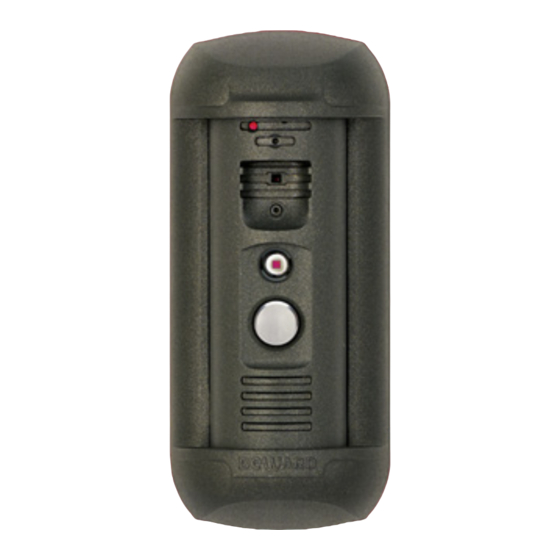
Chapter 3. Overview Chapter 3. Overview 3.1. Door Station A door station front view is given below: Pic. 3.1 1 – light sensor: a photoelectric cell that allows for automatic switching between Day and Night modes . 2 – built-in microphone: allows the Client to receive sound from the surveillance area. 3 –... -
Page 8: Controller
Chapter 3. Overview Pic. 3.2 8 – RJ45 socket: is used for connecting the door station to the NC103 / NC103P / NC311P controller via a patch cable. 9 – reset button: press this button 3 times with intervals not less than 1 second during 10 seconds to set door station settings by default. - Page 9 Chapter 3. Overview Pic. 3.4. Controller NC311P The front side of the NC311P controller also has the following: a light indicator of work state of the controller; a “LINK” button which is used for setting interaction between the controller and the door station;...
- Page 10 12V power supplying of the door station. It is necessary to connect a power supply recommended by BEWARD and the lock controller to these pins. The «G» and «12V» pins of the NC103P / NC311P controller (with PoE support) are used for powering the lock controller (several lock controllers) with DC 12V.
-
Page 11: Chapter 4. Door Station Installation
Chapter 4. Door Station Installation Chapter 4. Door Station Installation 4.1. General Information The door station can be connected directly to a computer or via a router (a switch). Pic. 4.1 The general instructions and installation recommendations are given below. IP Video Door Station DS06M(P) Installation User Manual... -
Page 12: Installation Recommendations
Chapter 4. Door Station Installation 4.2. Installation Recommendations This paragraph contains a short list of recommendations necessary for the correct installation of DS06M(P). IP Video Door Station DS06M is installed in the dry places on the surface of the inactive leaf of exterior double doors or on the wall of the building. - Page 13 Chapter 4. Door Station Installation Recommendations for twisted pair cable routing: In corridors, it is advisable to install electric and feeble-current cables in different conduits that are disposed on different walls. Twisted pair and electric cables can be installed in the same conduit using different sections of the cable that have solid longitudinal partitions with at least 0.25 h of fire resistance, which are made of non-combustible material and should be positioned in work areas at distance of 15 meters maximum if the electrical power does not exceed 5...
-
Page 14: Door Station Mounting
Chapter 4. Door Station Installation 4.3. Door Station Mounting Follow the steps below: Step 1: take the bracket plate (Pic. 4.2). Choose the right height of mounting above the floor. The recommended height is about 1.5 m. Step 2: mark the holes on the mounting surface using the bracket plate as a template. Drill the holes. - Page 15 Chapter 4. Door Station Installation Pic. 4.3 Step 5: before attaching a connector to the twisted pair cable put a rubber seal from the package contents on it to make to seal the connection area (Pic. 4.4). Pic. 4.4 Step 6: attach the RJ45-S01 connector from the package contents to the twisted pair cable using a crimping tool.
- Page 16 Chapter 4. Door Station Installation The patch cable must have the RJ45-S01 connector at the end connected to the door station! It is impossible to connect the door station using a cable connector of some other form. The twisted pair cable (5е UTP/FTP) connected the door station with its controller should be wired the same at both ends (“straight-through”...
- Page 17 Chapter 4. Door Station Installation Pic. 4.6 A view direction of the built-in IP-camera must be clearly determined at the moment of the door station installation (rotating angles are ±45° from the middle position). Step 9: apply the door station inserted in the bracket frame to the bracket plate fixed on the wall.
- Page 18 Chapter 4. Door Station Installation Pic. 4.8 Step 12: attach the RJ45 connector to the other end of twisted pair cable using a crimping tool as it described in the paragraph 4.5. ATTENTION! The twisted pair cable (5е UTP/FTP) connected the door station with its controller should have the same wire arrangement on both ends (“straight-through”...
- Page 19 (door station side). ATTENTION! Use only DC 12V power supplies recommended by BEWARD! For recommendations please visit our website (www.beward.net). It needs to highlight that the maximum current rate provided by the power source for supplying of the door station, door lock and other equipment should not be exceeded.
- Page 20 Chapter 4. Door Station Installation 2. With PoE (DS06MP package contents): Pic. 4.10 In this case the door lock and its controller are supplied with power by an external 12V power source, but the door station use PoE supplying. ATTENTION! Power supplying via both PoE and the «G»...
- Page 21 Chapter 4. Door Station Installation 3. It is available to supply all using devices with PoE (without use of an external power source) if the total energy consumption of using electronic normally closed lock and its controller is not bigger than 500 mA. In this case the recommended connection scheme is as follows: Pic.
-
Page 22: Memory Card Installation
If PoE is not used, then connect the RJ45 socket (ETHERNET) of the NC103 controller to a router using the crimped cable and connect the «G» and «12V» pins of the controller with an external DC 12V power source. To prevent the door station malfunction use only equipment recommended by BEWARD. 4.4. Memory Card Installation ATTENTION! Switch off the door station before installation/ejection of the memory card. -
Page 23: Wired Connection To A Network
Chapter 4. Door Station Installation 4.5. Wired Connection to a Network Connect the door station controller to the local network (to the router’s LAN interface) using a twisted pair cable with RJ45 connectors. You can purchase the network cable separately or if you have materials, tools and skills, you can make it by yourself. -
Page 24: Chapter 5. Wired Connection Setting
Chapter 5. Wired Connection Setting Chapter 5. Wired Connection Setting To make the door station work together with computers, laptops and other devices in your local network, you need to connect it to the network according to the network parameters. This chapter explains how to set the network parameters. - Page 25 Chapter 5. Wired Connection Setting Pic. 5.2 In the new window click [Local Area Connection] (Pic. 5.3). Pic. 5.3 NOTE: If there are several active networks, choose the one that you are going to connect your door station to. IP Video Door Station DS06M(P) Installation User Manual...
- Page 26 Chapter 5. Wired Connection Setting In the new window click the [Properties] button (Pic. 5.4). Pic. 5.4 In the opened window select the [Internet Protocol Version 4 (TCP/IPv4)] menu item and click the [Properties] button (Pic. 5.5). Pic. 5.5 The window opens displaying information about the network connection settings. There are two ways to configure the IP address: IP Video Door Station DS06M(P) Installation User Manual...
- Page 27 Chapter 5. Wired Connection Setting 1. Obtain an IP address automatically: select this option to obtain the IP address automatically from a DHCP-server on your network (Pic. 5.6). If the IP address is assigned to your computer automatically, go to paragraph 5.1.1 to define the network parameters.
-
Page 28: Defining The Local Network Parameters When Using A Dynamic Ip Address
Chapter 5. Wired Connection Setting ATTENTION! If you forget the network parameters it is impossible to return the computer’s network settings to their original state and to connect it to a local network or the Internet after configuring the door station. 5.1.1. - Page 29 Chapter 5. Wired Connection Setting Pic. 5.9 In the new window click [Local Area Connection] (Pic. 5.10). Pic. 5.10 NOTE: If there are several active networks, choose the one that you are going to connect your door station to. IP Video Door Station DS06M(P) Installation User Manual...
- Page 30 Chapter 5. Wired Connection Setting In the opened window click the [Details] button (Pic. 5.11). Pic. 5.11 In the opened window you can see the current network connection details (Pic. 5.12). Pic. 5.12 IP Video Door Station DS06M(P) Installation User Manual...
-
Page 31: Changing The Local Network Parameters
Chapter 5. Wired Connection Setting If you will see the following information in the opened window: [DHCP Enabled – Yes], [IPv4 Address – xxx.xxx.xxx.xxx] (where xxx.xxx.xxx.xxx is an IP address value), it means that your computer is assigned the IP address displayed in the [IPv4 Address] line, the subnet mask displayed in the [IPv4 Subnet Mask] line, the gateway address displayed in the [IPv4 Default Gateway] line, the DNS server address displayed in the [IPv4 DNS Server] line. - Page 32 Chapter 5. Wired Connection Setting Pic. 5.13 In the new window click [View network status and tasks] in the [Network and Internet] section (Pic. 5.14). Pic. 5.14 In the new window, click [Local Area Connection] (Pic. 5.15). IP Video Door Station DS06M(P) Installation User Manual...
- Page 33 Chapter 5. Wired Connection Setting Pic. 5.15 NOTE: If there are several active networks, choose the one that you are going to connect your door station to. In the new window, click the [Properties] button (Pic. 5.16). Pic. 5.16 IP Video Door Station DS06M(P) Installation User Manual...
- Page 34 Chapter 5. Wired Connection Setting In the connection properties window select the [Internet Protocol Version 4 (TCP/IPv4)] menu item and click the [Properties] button (Pic. 5.17). Pic. 5.17 In the new window you need to specify an IP address and a subnet mask. Click the [Use the following IP address] and type an unused IP address from the same subnet as the door station, for example, 192.168.0.20, and 255.255.255.0 in the [Subnet mask] field.
-
Page 35: Accessing The Door Station Using Internet Explorer
To work with the door station web interface you need to install the ActiveX add-on. You will see the system notification at the bottom of the window: “This webpage wants to run the following add-on: “AxMediaControl ActiveX Control Module” from “BEWARD Co., Ltd” (Pic. 5.20). - Page 36 Chapter 5. Wired Connection Setting Pic. 5.20 Click [Allow] to start installation. ATTENTION! Installation of ActiveX components is only possible for 32-bit Internet Explorer. By default, the Internet Explorer security system blocks ActiveX installation. Click [Install] to continue (Pic. 5.21). Pic.
- Page 37 Chapter 5. Wired Connection Setting Pic. 5.22 Close Internet Explorer and click [OK]. You need close the browser before installation anyway, whether the window on the Picture 5.22 will appear or not. The installation window will appear. Click [Install] (Pic. 5.23). Pic.
- Page 38 Chapter 5. Wired Connection Setting ATTENTION! You can change login and password in the menu Config – System – Access Policy after authorization. If you lost your login or password, you can restore the default settings of the door station. To set the device by default press the reset button 3 times during 10 seconds with 1 second or more between the pushes.
- Page 39 Chapter 5. Wired Connection Setting If you failed to install ActiveX correctly you can do it again by clicking the link in the authorization window (Pic. 5.27) and following the instructions above. Pic. 5.27 IP Video Door Station DS06M(P) Installation User Manual...
-
Page 40: Configuring Door Station Network Settings Through The Web Interface
Chapter 5. Wired Connection Setting 5.5. Configuring Door Station Network Settings through the Web Interface After connecting the door station to the local network you need to change its network parameters to get it and your other devices (e.g. computer, laptop etc.) to the same subnet. ATTENTION! To make your door station and your computer work together, the first three parts of their IP addresses must be identical but the fourth must differ. -
Page 41: Restoring Network Settings Of Pc To The Previous Values
Chapter 5. Wired Connection Setting 5.6. Restoring Network Settings of PC to the Previous Values To restore the wired connection settings to their previous values, follow the steps below. Go to Start – Control Panel (Pic. 5.29). Pic. 5.29 In the new window, click [View network status and tasks] in the [Network and Internet] section (Pic. - Page 42 Chapter 5. Wired Connection Setting In the new window, click [Local Area Connection] (Pic. 5.31). Pic. 5.31 In the new window, click the [Properties] button (Pic. 5.32). Pic. 5.32 Select the [Internet Protocol Version 4 (TCP/IPv4)] menu and click the [Properties] button (Pic.
- Page 43 Chapter 5. Wired Connection Setting Pic. 5.33 In the new connection properties window you need to specify your initial network settings (see paragraphs 5.1, 5.1.1). If the IP settings were assigned automatically, use the [Obtain an IP address automatically] and the [Obtain DNS server address automatically] options (Pic. 5.34), then click [OK].
-
Page 44: Verifying The Connection Settings
Chapter 5. Wired Connection Setting If the IP settings were specified manually, use the [Use the following IP address] and the [Use the following DNS server addresses] options and complete the required fields (see paragraph 5.1), then click [OK] (Pic. 5.35). Pic. - Page 45 Chapter 5. Wired Connection Setting If the settings are correct, the authorization window will appear. Enter the username and password, then click [OK] (Pic. 5.37). ATTENTION! The default username is admin, the default password is admin. Pic. 5.37 If everything is done correctly, you will see the video image on your display (Pic. 5.38). IP Video Door Station DS06M(P) Installation User Manual...
- Page 46 Chapter 5. Wired Connection Setting c. 5.38 NOTE: If the video image did not appear on your display, return to the beginning of the chapter and check the settings step by step. Contact your system administrator if you need help. IP Video Door Station DS06M(P) Installation User Manual...
-
Page 47: Chapter 6. Recommendations On Setting And Operation Of Ds06M(P)
Chapter 6. Recommendations on Setting and Operation of DS06M(P) Chapter 6. Recommendations on Setting and Operation of DS06M(P) IP intercom systems combine different types and configurations of equipment (PCs, laptops, microphones, speakers, etc.). Therefore, correct operation of the whole system depends on proper setting of each device used taking into account the peculiarities of their joint operation. -
Page 48: Sound Gain And Volume Adjusting
Chapter 6. Recommendations on Setting and Operation of DS06M(P) NOTE! These settings are audio hardware and software specific and may not be available for all microphones. NOTE! The names of options in the OS menus may differ from the ones mentioned above. 2. - Page 49 Chapter 6. Recommendations on Setting and Operation of DS06M(P) Moreover, you can adjust the gain of sound transmitted from the PC microphone to the door station speaker in the Web User Interface. Go to Config – Audio Settings – Audio Parameter and change the “Output Volume”...
-
Page 50: Appendices
Appendices Appendices Appendix A. Factory Defaults Parameter Value IP address 192.168.0.99 Subnet mask 255.255.255.0 Gateway 192.168.0.1 Username (administrator) admin Password (administrator) admin HTTP port Data port 5000 RTSP port ONVIF port 2000 NTP server time.nist.gov time.windows.com time-nw.nist.gov time-a.nist.gov time-b.nist.gov Appendix B. Glossary Client is person who controls a door station using computer. - Page 51 Appendices with him using a microphone and speakers / headphones. The Client can control the electronic door lock and some other devices connected to the door station controller. PoE Injector is a device that stands between a regular Ethernet switch and the powered device (for example, door station PoE supported controller), injecting power and transferring the data via the same cable.
Need help?
Do you have a question about the DS06M(P) and is the answer not in the manual?
Questions and answers