Table of Contents
Advertisement
Original instructions
1
Description ............................................................................................................ 2
2
Technical data ....................................................................................................... 3
3
Technical data sheet ............................................................................................. 4
4
Plates ..................................................................................................................... 4
4.1 Plates on DCRM24 unit in a radio remote control ............................................. 4
4.2 Plates on DCRM24 unit in a Take & Release radio remote control ................... 4
5
Warnings for installation ...................................................................................... 5
5.1 Wiring .............................................................................................................. 5
6
Light signals .......................................................................................................... 6
6.1 POWER LED (green) ....................................................................................... 6
6.2 ENABLE LED (green) ...................................................................................... 6
7
Operation ............................................................................................................... 6
7.1 Electronic module ............................................................................................ 6
7.2 DIP switches .................................................................................................... 6
7.3 Internal light signals ......................................................................................... 6
7.4 Command outputs ............................................................................................ 6
8
Malfunction signalled by the receiving unit ........................................................ 7
AUTEC
Air series
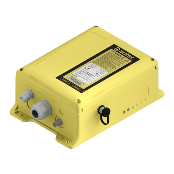
Part D: receiving unit
DCrM24 (rMG)
inDex
LIRMGE00-01
Advertisement
Table of Contents

Related Manuals for AUTEC DCRM24


Summary of Contents for AUTEC DCRM24
- Page 1 4.1 Plates on DCRM24 unit in a radio remote control ..........4 4.2 Plates on DCRM24 unit in a Take & Release radio remote control ....4 4.3 Plates on DCRM24 unit in a Multi Units or Multi Receiver radio remote control 5 Warnings for installation ..................5 5.1 Wiring ......................
-
Page 2: Description
DIP switches Internal light signals Connector for the cable control's wiring SAFETY contacts protection fuse Outputs of relay commands SAFETY output STOP outputs Connectors for power supply Power supply protection fuse Outputs of solid state commands LIRMGE00-01 AUTEC - Air series... -
Page 3: Technical Data
Command contacts' rated current for any optional card is provided in the technical data sheet. The rated current may be up to 10A only if both terminals are used for each contact. If the radio remote control has been wired by Autec, please refer to values provided in the technical data sheet. -
Page 4: Technical Data Sheet
On the cover of the technical data plate technical data, marking and possible receiving unit. radio remote control marks. Plates on DCrM24 unit in a Take & release radio remote control Plate Position Content radio remote control On the cover of the... -
Page 5: Plates On Dcrm24 Unit In A Multi Units Or Multi Receiver Radio Remote Control
Warnings for installation Plates on DCrM24 unit in a Multi Units or Multi receiver radio remote control Plate Position Content Radio remote control serial number radio remote control On the cover of each (MULTI S/N), bar code and identification plate receiving unit. -
Page 6: Light Signals
The activation of each relay on the mother board is signalled by an LED near the relay. Command outputs The data sheet contains information regarding the correspondence between the commands sent by the transmitting unit and the related output enabled in the receiving unit. LIRMGE00-01 AUTEC - Air series... -
Page 7: Malfunction Signalled By The Receiving Unit
Check the protection fuses of the STOP LeD blinks fast. the commands sent. contacts or of the SAFETY contacts and, if needed, replace them. AUTEC - Air series LIRMGE00-01...
Need help?
Do you have a question about the DCRM24 and is the answer not in the manual?
Questions and answers