Table of Contents
Advertisement
Quick Links
Technical Manual
Instructions for installation,
operation and maintenance
641
®
OILCON
MARK 6M
According regulation 31 Annex I of MARPOL 73/78,
IMO Resolution MEPC.108(49) and IMO Resolution MEPC.240(65)
Oil Discharge Monitoring and Control System
Publication nr
Supersedes
TIB-641-GB-1117
TIB-641-GB-0617
Advertisement
Table of Contents

Subscribe to Our Youtube Channel
Summary of Contents for VAF instruments OILCON MARK 6M
- Page 1 Technical Manual Instructions for installation, operation and maintenance ® OILCON MARK 6M According regulation 31 Annex I of MARPOL 73/78, IMO Resolution MEPC.108(49) and IMO Resolution MEPC.240(65) Oil Discharge Monitoring and Control System Publication nr TIB-641-GB-1117 Supersedes TIB-641-GB-0617...
-
Page 2: Table Of Contents
CONTENTS PREFACE ..................6 General ...................... 6 Symbols ..................... 7 Copyright ....................7 PRODUCT DESCRIPTION ............. 8 Principle of operation ................. 8 Product configuration ................. 9 2.2.1 ... - Page 3 6.4.1 Sample pump ....................29 6.4.2 Air pipelines ....................29 6.4.3 Intrinsically Safe signal cable ............... 30 Electrical installation general ..............31 6.5.1 Electro Pneumatic Unit (EPU) ..............31 6.5.2 Starter box ....................32 Control room equipment – Main Control Unit (MCU) ........ 32 ...
- Page 4 7.3.1 Discharging ballast water ................65 7.3.2 Shutdown of discharging operations ............67 Miscellaneous ..................68 7.4.1 Oil content reading higher than expected ............. 68 7.4.2 Oil level alarm ....................68 Operational alarms ................... 69 System failures ..................70 ...
- Page 5 DISPOSAL ..................90 TROUBLE SHOOTING AND FAULT FINDING ......91 15.1 Introduction fault finding guide .............. 91 15.2 Fault finding guide ................. 92 15.3 Calibration alarms ................. 94 15.3.1 Zero error alarm .................... 94 15.3.2 ...
- Page 6 DRAWINGS ..................126 ABBREVIATIONS ................168 18.1 Abbreviations ..................168 18.2 Symbol list ..................168 SPARE PARTS ................169 19.1 Standard spares .................. 169 19.2 Servicing spares ................. 169 WARRANTY CONDITIONS ............171 ...
-
Page 7: Preface
Oilcon Oil Discharge Monitor and Control System. For IOM information of associated equipment supplied by VAF Instruments, refer to the separate manual supplied with those products. This manual contains important information for the installer, the operator and for your maintenance department. -
Page 8: Symbols
While every precaution has been taken in the preparation of this manual, no responsibility for errors or omissions is assumed. Neither is any liability assumed for damages resulting from the use of the information contained herein. Specifications can be changed without notice. ® Oilcon is a registered trademark of VAF Instruments B.V. -
Page 9: Product Description
2 PRODUCT DESCRIPTION ® The Oilcon Oil Discharge Monitoring and Control System continuously samples ballast water being discharged overboard and measures the oil content and controls the discharge of the ballast water and plays therefore a central role in the Oil Discharge Monitor and Control System. ®... -
Page 10: Product Configuration
2.2 PRODUCT CONFIGURATION ® The Oilcon Oil Discharge Monitoring and Control System comprises the elements labelled as: Main Control Unit (MCU). Electro Pneumatic Unit (EPU) o I/S signal cable o Starter box Skid assembly Pump/motor assembly ... -
Page 11: Electro Pneumatic Unit (Epu)
2.2.2 Electro Pneumatic Unit (EPU) Reference drawings Dimensional drawing and parts list EPU 1-2 sample valves Mark 6M 0806-1287 The Electro Pneumatic Unit (EPU) contains the control electronics and the solenoid valves to switch the pneumatic signals. It also contains the Zener barriers for the input signals from the flowmeter(s), skid flow meter and measurement cell. -
Page 12: Skid Assembly
2.2.3 Skid assembly Reference drawings Dimensional drawing and parts list ballast skid Mark 6M 0806-1288 The skid assembly contains the necessary items to handle the sampled ballast water and to measure the oil content. In the skid assembly there is a pneumatically operated shuttle valve (5), and a window wash pump (1). -
Page 13: Sample Probe Valve Assembly
2.2.6 Sample probe valve assembly Reference drawings Dimensional drawing sample valve Mark 6 0806-1077 Part list sampling probe pipe connection Ø15 mm Ballast Monitor Mark 6M 0806-1265 Part list isolating valve Ø15 Ballast Monitor Mark 6 0806-1268 For taking a representative sample of the ballast water to measure the oil level content, a sample probe valve assembly is provided. - Page 14 CONTROL Sample point: 1 22-11-11 window wash Oil type: 5 10:38 Concentration discharge Flow m3/h dirty Skid Flow com: O Speed 10.0 pos: O Discharge rate l/nm segregated Total oil com: C Latitude 5321.756N pos: C Longitude 00711.854E EPU: OK free: 1927296 kB Figure 2 For correct operation of the system it is important, that during operations an un-interrupted supply of...
-
Page 15: Technical Specification
3 TECHNICAL SPECIFICATION 3.1 GENERAL Range 0 – 1000 ppm Type of oils In accordance with type approval certificate oils as per MEPC 108(49) and biofuel blends as per MEPC 240(65) Accuracy In accordance with IMO Resolution MEPC 108 (49), the system response is within the accuracy specified. -
Page 16: Electro Pneumatic Unit (Epu)
Output signals USB Flash drive with a type A connector USB 1.0 compatible and formatted according to FAT16 Serial output Alarm relay (X3) NO/NC contact, rating 250 VAC – 5 A or 30 VDC – 5 A Failure-24V relay (X4) NO/NC contact, rating 250 VAC –... -
Page 17: Skid
3.4 SKID Sample flowrate between 450 and 550 l/h Sample inlet pressure 3 bar (nom.), 6 bar (max.) (0.3 MPa nom., 0.6 MPa max.) Fresh water supply 3 bar (nom.), 6 bar (max.) (0.3 MPa nom., 0.6 MPa max.) average consumption 0,13 l/min max. -
Page 18: Reference Table Of Products Which May Be Measured
3.6 REFERENCE TABLE OF PRODUCTS WHICH MAY BE MEASURED Crude oils, and “black” and “white” products (Annex I) Range number Product Marine Distillate Fuel oil Category 1 crude oil Category 2 crude oil Category 3 crude oil Category 4 crude oil Category 5 crude oil Category 6 crude oil Automotive Gasoline... -
Page 19: Biofuel Guidelines And Definitions
3.7 BIOFUEL GUIDELINES AND DEFINITIONS According MEPC.1/Circ.761 the following definitions are given. Bio-fuels are ethyl alcohol, fatty acid methyl esters (FAME), vegetable oils (triglycerides) and alkanes (C10-C26), linear and branched with a flashpoint of either 60°C or less or more than 60°C, as identified in chapters 17 and 18 of the IBC Code or the MEPC.2/Circular/tripartite agreements. -
Page 20: Safety Instructions
4 SAFETY INSTRUCTIONS 4.1 SAFETY PRECAUTIONS All precautions have been taken to ensure, in so far as reasonable practical, that the equipment has been designed and constructed to be safe and without risk to health or the environment when properly used. Provided that the recommendations contained in this manual are carefully adhered to, no circumstances are foreseen where the equipment will present a health or safety hazard. -
Page 21: Unpacking
5 UNPACKING Let the equipment acclimatize inside the closed box for at least one hour at the location where the ® Oilcon Oil Discharge Monitoring and Control System will be installed. When the equipment is taken out of the box, please leave the special protection supplied with the equipment as long as possible in place to avoid any damage. - Page 22 Orifice Plate Thickness: 6 mm Material: Stainless Steel Diameter and bore: Specific to each installation Figure 7: Electronic Differential Pressure Transmitter and Orifice Plate Skid Assembly Weight: 20 kg Dimensions: 500 mm x 420 mm x 177 mm (W x H x D) Air Connections: 6 mm and 10 mm tube Water connections:...
-
Page 23: Installation
6 INSTALLATION 6.1 INTRODUCTION This specification sets out the requirements for the installation, operation and maintenance of an ® Oilcon Oil Discharge Monitoring and Control System on board a typical tanker. It should be studied carefully before actually commencing any operation or work. For the purpose of installation the system can be divided into 4 categories: 1. -
Page 24: Air Supply
6.2.2 Air supply ® For a trouble free and satisfactory operation of the pneumatic components in the Oilcon Discharge Monitoring and Control System a supply of clean, dry air at a constant pressure is essential. Air supply conditions EPU Valve control 4,0 bar nom., 7 bar max. -
Page 25: Sample Pump Unit
CAUTION: BEFORE THE SYSTEM IS PUT INTO OPERATION OR TESTED ALL PIPEWORK MUST BE FLUSHED AND CLEARED FROM DIRT OR FOREIGN MATTER. Reference drawings Dimensional drawing and parts list ballast skid Mark 6M 0806-1288 Schematic installation diagram Oilcon Monitor System with 1x dP/I transmitter Mark 6 0806-8035 ... -
Page 26: Electrical Installation Pump
Before connecting the system piping to the pump, the unit is to be securely fastened to the bulkhead. Long or heavy piping sections shall not be supported from the pump but by separate supports. ALIGNMENT: No inspection or corrections to pump/motor alignment are necessary. Install the oil reservoir and top up the reservoir with the supplied oil. -
Page 27: Skid
Where it is not possible to mount into a vertical pipe then a horizontal section may be used and the probe located as shown in drawing 0806-1265. VAF Instruments recommend that whenever possible the sample probe should be installed on the upstream side of the orifice plate. -
Page 28: Orifice Plate
5 x pipe diameters after the orifice plate. It must be stressed that if above installation requirements cannot be met, VAF Instruments should be consulted for advice. VAF Instruments cannot held be responsible for any flowmetering system installed incorrectly or without due consultation. -
Page 29: Dp/I Transmitter
6.3.8 dP/I transmitter The electronic differential pressure transmitter is a two- wire transmitter which converts the differential pressure developed by the flow sensor into a 4–20mA signal. Select a location for the transmitter that is close to the orifice plate, not exceeding 16m and where the ambient temperature will not exceed 90°C nor be less than -40°C. -
Page 30: Bulkhead Penetrations General
WARNING: IN HAZARDOUS ZONES WITH EXPLOSION PROOF REQUIREMENTS THE COVERS MUST BE TIGHTENED WITH AT LEAST 7 TURNS. IN HAZARDOUS ZONES WITH INTRINSICALLY SAFE OR NON-INCENDIVE REQUIREMENTS, THE CIRCUIT ENTITY PARAMETERS AND APPLICABLE INSTALLATION PROCEDURES MUST BE OBSERVED. CABLE ACCESS TO WIRING CONNECTIONS IS OBTAINED BY ONE OF THE TWO CABLE CONDUIT OUTLETS. -
Page 31: Intrinsically Safe Signal Cable
The replacement of components can only be done by personnel trained to act on equipment intended for use in potentially explosive atmospheres. Spare parts must only be genuine parts supplied by VAF Instruments. During installation there is no need to operate the system and thus to switch the EPU on. -
Page 32: Electrical Installation General
Maximum fuse current 16A. Cable terminations for individual conductors should be finished with a pin terminal crimped on the conductor. Cables are not supplied by VAF Instruments, unless specifically ordered. 6.5.1 Electro Pneumatic Unit (EPU) -
Page 33: Starter Box
6.5.2 Starter box The starter box is used to switch and control the electrical supply to the sample pump motor and contains a relay and thermal relay to protect the pump for overheating. It may be mounted to any suitable location adjacent to the EPU or pump motor. The unit is mounted by four holes which accept 4 mm bolts. -
Page 34: Installation Checklist
6.7 INSTALLATION CHECKLIST 6.7.1 General installation checks 1. Is all pipework of correct materials and dimensions? 2. Is all pipework adequately supported? 3. Does the maximum distance from furthest sample probe to the skid give a system response time of less than 40sec? 4. -
Page 35: Starting Interlock And/Or Overboard Valve Control
6.7.3 Starting interlock and/or overboard valve control IMO Resolution MEPC 108 (49) entitled: ® “Guidelines and specifications for Oilcon Oil Discharge Monitoring and Control Systems for tankers” ® Oil tankers of 150 gross tonnage and above shall be fitted with an Oilcon Oil Discharge Monitoring control system approved by the Administration and designed and installed in compliance with the Guidelines and Specifications for Oil Discharge Monitoring and Control Systems for Oil Tankers... -
Page 36: Pipework Response Time Calculation
0806-5019. This also incorporates a starting interlock. VAF Instruments advise that prior consultation is made with the classification society surveyor in each case to ensure that the arrangement will be acceptable both as to the operation and with regard to safety. -
Page 37: Final Check
0.015 Internal surface area of the pipe 0.001 2 ∙ 0.015 2 ∙ 0.001 0.013 ∙ ∙ 0.013 1.33 ∙ 10 0.5 Sample flow rate ∙ Therefore ∙ . ∙ . ∙ ∙ 30.5 6.7.5 Final check Has completed system been inspected as a whole with regard to safety? -
Page 38: Overview Installation Check
6.8 OVERVIEW INSTALLATION CHECK 6.8.1 Cable connection Main Control Unit Reference drawings Electrical connection diagram Ballast Monitor Mark 6M MEPC 108(49) 0806-2048 Connection diagram Oilcon Mark 6 Cable spec. MEPC 108(49) 0806-2050 Figure 10 Figure 11 Screen and tension clamp (see Figure 10): ... -
Page 39: Intrinsically Safe Ground Points, Measurement Cell And Epu
Figure 13 Figure 14 Figure 15 All cable connections to EPU and Connection Box Skid Strip the cable Guide the stripped cable through the synthetic insert M Fold back the screen over the synthetic insert M Push the synthetic insert M in the cable gland N ... -
Page 40: Power Supply Starter Box And Cable Connection Skid
6.8.4 Power supply starter box and cable connection skid Reference drawings Control drawing for Mark 6M Oil Discharge Monitor 0806-0005 Electrical connection diagram Ballast Monitor Mark 6M MEPC 108(49) 0806-2048 Figure 20 Figure 19 Figure 21 P. Power supply to starter box IC-08 Q. -
Page 41: Multi Cable Transit (Bulkhead Penetration)
6.8.5 Multi Cable Transit (Bulkhead Penetration) Reference drawings Multi cable transit Ballast Monitor Mark 6 0806-8070 Figure 22 Figure 23 Figure 24 Installation of MCT Place insert-blocks U Place cables and air pipes in accordance with size of the insert-blocks ... -
Page 42: Water And Airline Connections Skid
6.8.6 Water and Airline connections Skid Reference drawings Dimensional drawing and parts list EPU 1-2 sample valves Mark 6M 0806-1287 Dimensional drawing and parts list ballast skid Mark 6M 0806-1288 Bulkhead penetration and piping diagram Mark 6M 0806-8038 CC DD Figure 25... -
Page 43: System Settings
6.8.7 System settings. Figure 29 Figure 30 Fresh water regulator JJ. Water pressure set knob, set pressure to 1,5 bar KK. Fresh water filter Air regulator LL. Air pressure set knob, set pressure to 4 bar minimum Figure 31 Starter Box MM. -
Page 44: Operating Instructions
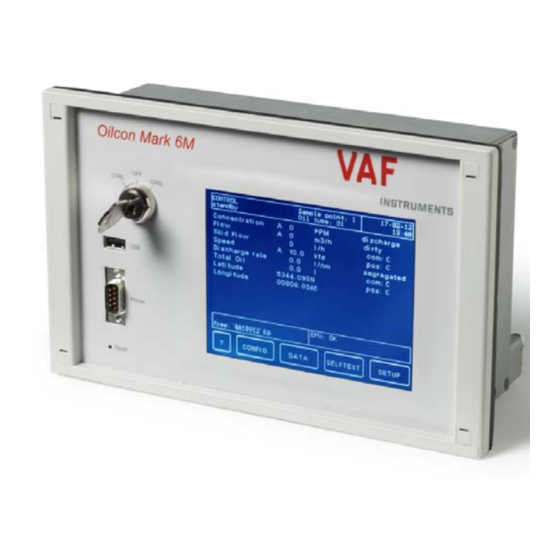
7 OPERATING INSTRUCTIONS 7.1 LAYOUT OF THE MCU ® Operation of the Oilcon Oil Discharge Monitoring and Control System is controlled and recorded by the MCU. A representation of the control panel of the MCU, as fitted in the Cargo Control Room, is shown below. -
Page 45: Usb Connector
A printout of the data can be made following the procedure as describe in section 7.2.1.3. A printer is not provided by VAF Instruments. Since all data is saved in the internal memory of the MCU and can by copied to a USB flash drive there is no actual need for a printer. -
Page 46: Operating The Mcu And Menu Layout
7.2 OPERATING THE MCU AND MENU LAYOUT The MCU has a menu layout as show below. STARTUP WARNING 1.2.1 CONFIG 1.2.2 1.2.3 1.2.4 1.2.5 1.2.6 1.2.7 1.2.8 1.2.9 1.2.10 1.3.1 1.2.11 DATA PRINTER 1.2.12 1.2.13 1.2.14 1.3.2 1.2.15 1.2.16 SELFTEST 1.5.1 SETUP 1.5.2.1... - Page 47 In the different menus the following keys are available: Navigation Operations BACK Previous menu SAMPLE Start sampling operations Scroll up STOP Stop sampling operations DOWN Scroll down FLUSH Start flush sequence Previous screen W WASH Start windows wash sequence Next screen Next setting Previous setting Menus...
-
Page 48: Standby Mode (Menu 1)
7.2.1 Standby mode (menu 1) When the MCU and EPU are both powered on and the key switch is turned to the “Control” position, the MCU goes into the standby mode in menu 1. CONTROL Sample point: 1 22-11-11 standby Oil type: 5 10:38 Concentration... -
Page 49: Information Mode (Menu 1.1)
7.2.1.1 Information mode (menu 1.1) The information mode is entered when the < ? > key is pressed in menu 1. The mode gives additional information about system operation and operational actions which can be taken if e.g. an alarm situation occurs. Depending from which menu the information mode is activated, different texts will be displayed. -
Page 50: Configuration Mode (Menu 1.2)
7.2.1.2 Configuration mode (menu 1.2) The configuration mode is entered when the <CONFIG> key is pressed in the menu 1. The mode is used to set up the system during installation and this should only be done by a trained service engineer. - Page 51 When the <PRV> or <NXT> key is pressed, the previous or next setting is selected and value entered in the current menu is automatically stored. The following settings in the configuration menu (menu 1.2.1 up to menu 1.2.16) can be set: Menu Description Range...
-
Page 52: Data Mode (Menu 1.3)
7.2.1.3 Data mode (menu 1.3) The data mode is entered when the <DATA> key is pressed in the menu 1. The mode is used to print out logged data with a printer or copy this data to a USB flash drive. In the data mode a selection has to be made whether the data is printed to a printer or copied to a USB flash drive. -
Page 53: Selftest Mode (Menu 1.4)
The MCU logs data at the following intervals: at the start and at the end of the discharge operation; at ten minutes intervals (or less, if set by the operator); at the occurrence of any alarm; if automatic or manual mode is selected;... -
Page 54: Setup Mode (Menu 1.5)
7.2.1.5 Setup mode (menu 1.5) The setup mode is entered when the <SETUP> key is pressed in the menu 1. The mode is used to setup the system for a specific discharge operation. When the setup menu is entered, 3 options are available: ... - Page 55 Total oil limit According to the regulations the maximum “total oil limit” should never exceed: 1/30.000 of the last cargo by a new ship 1/15.000 of the last cargo by an old ship Reset total oil Accoring to the regulations only at the start of each new ballast voyage it is allowed to reset the total oil amount.
-
Page 56: Setup Mode (Menu 1.5.2)
7.2.1.5.2 Setup mode (menu 1.5.2) The setup mode is entered when the <CHANGE> key is pressed in the menu 1.5.2. In order to setup the system for a specific ballast water discharge, it is necessary to enter specific parameter settings. In the setup mode the settings can be changed by either entering a numeric value or by selecting a preset value. - Page 57 The following settings in the setup menu (menu 1.5.2.1 up to menu 1.5.2.13) can be set: Menu Description Range Remark 1.5.2.1 Sample point 1…6 The value to be entered is the number of the sample point from which a sample is taken. 1.5.2.2 Discharge mode clean ballast / dirty ballast...
-
Page 58: Calibration Flush Mode (Menu 1.5.3.0)
7.2.1.5.3 Calibration flush mode (menu 1.5.3.0) After the <FLUSH> key in the setup mode (menu 1.5) is pressed, the system prepares to go into sampling mode by initiating a calibration flush sequence. The calibration flush sequence is used to clean the system prior to sampling and to check the condition of the detector cell and the system. -
Page 59: Idle Mode (Menu 1.5.3)
7.2.1.5.4 Idle mode (menu 1.5.3) After the flush sequence has finished and idle mode has been reached the system is ready for discharge operations. The system stays idle until the operator enters the next command. From idle mode the following modes can be selected: ... -
Page 60: Shutdown Mode (Menu 1.5.3.2)
7.2.1.5.4.2 Shutdown mode (menu 1.5.3.2) The shutdown mode is entered when the <STOP> key is pressed in menu 1.5.3. If the shutdown mode is entered from idle mode (menu 1.5.3) the system will initiates a shutdown sequence. The shutdown sequence consists of approximately 2 minutes backward flush and 2 minutes forward flush. -
Page 61: Idle Setup Mode (Menu 1.5.3.3)
7.2.1.5.4.3 Idle setup mode (menu 1.5.3.3) The idle setup mode is entered when the <CHANGE> key is pressed in menu 1.5.3. In menus 1.5.2.1 – 1.5.2.13 the system has been setup for a specific discharge operation. Next the system goes through the calibration flush sequence, cleaning and calibrating the system and reading it for discharging ballast water. -
Page 62: Self Test Mode (Menu 1.5.3.4)
7.2.1.5.4.4 Self test mode (menu 1.5.3.4) The selftest mode is entered when the <SELFTEST> key is pressed in menu 1.5.3. In the self test mode and internal loop is checked and an overview is displayed of all alarms since the MCU is last powered down. CONTROL Sample point: 1 22-11-11... -
Page 63: Information Mode (Menu 1.5.3.5.1)
7.2.1.5.4.5.1 Information mode (menu 1.5.3.5.1) The information mode is entered when the < ? >key is pressed in menu 1.5.3.5. The mode gives additional information about system operation and operational actions which can be taken if e.g. an alarm situation occurs. Depending from which menu the information mode is activated, different texts will be displayed. -
Page 64: Manual Flush Mode (Menu 1.5.3.5.3)
7.2.1.5.4.5.3 Manual flush mode (menu 1.5.3.5.3) The manual flush mode is entered when the <FLUSH> key is pressed in menu 1.5.3.5 After the <FLUSH> key is pressed, the system initiates a manual flush sequence. The sequence consists of approximately 12 seconds window wash and a total of 3 minute forward flush and calibration. -
Page 65: Self Test Mode (Menu 1.5.3.5.5)
7.2.1.5.4.5.5 Self test mode (menu 1.5.3.5.5) The selftest mode is entered when the <SELFTEST> key is pressed in menu 1.5.3.5.5. In the self test mode and internal loop is checked and an overview is displayed of all alarms since the MCU is last powered down. CONTROL Sample point: 1 22-11-11... -
Page 66: Short Reference Guide For Operating The Mcu
7.3 SHORT REFERENCE GUIDE FOR OPERATING THE MCU NOTE: ® The Oilcon Oil Discharge Monitoring and Control System must be operated as directed under the regulations given in Marpol 73/78, to prevent discharge of oil contaminated water overboard. Where instructions in this manual may apparently conflict with the Marpol requirements, then at all times the Marpol regulations are leading. - Page 67 Press the SETUP key to enter the setup mode. Check if all parameter in the setup are correct and change them if necessary. o Sample point 1…6 o Discharge mode clean ballast/dirty ballast o Total oil limit 0…40,000 l o Reset total oil Yes/No o Discharge alarm...
-
Page 68: Shutdown Of Discharging Operations
Increase the speed of the cargo pump. Watch the discharge rate on the MCU, it will increase as the speed of the cargo pump is increased. NOTE: If the discharge rate approaches the maximum permissible (i.e. 30 l/NM), it can be reduced by slowing down the cargo pump. -
Page 69: Miscellaneous
7.4 MISCELLANEOUS This section is to describe problems that may be encountered during operation and the possible reasons. 7.4.1 Oil content reading higher than expected During a normal discharge run of ballast water the ppm reading should be between 50 to 150 ppm assuming that sufficient time has been left to allow the oil to settle out in the tank. -
Page 70: Operational Alarms
7.5 OPERATIONAL ALARMS NOTE: ® At all times the Oilcon Oil Discharge Monitoring and Control System must be operated as directed by MARPOL 73/78 to prevent discharge of oil contaminated water overboard. There are necessarily a number of alarm conditions in the MCU. Irrespective of what caused the alarm, the result is the same. -
Page 71: System Failures
Alarm Description ® If for any reason there is no flow through the Oilcon Oil Discharge Monitoring and Control System the NO FLOW alarm is activated. The Sample pump will be stopped automatically to prevent any damage to the pump or motor. No flow If in flush or shutdown mode the system will return to standby mode. -
Page 72: Flowmeter
7.6.1.1 Flowmeter In the event of failure of the discharge flow metering system, the flow rate should be estimated by the best means available and entered into the MCU manually as described above. The flowrate can be estimated by: cargo pump characteristic curves, a copy of which should be included in this manual;... -
Page 73: System Overrides
7.7 SYSTEM OVERRIDES The MCU provides a number of output signals to allow flexible means of controlling the ballast water discharge system. Two outputs are under the direct control of the MCU and these are used to automatically control the discharge system: to stop the discharge when the alarm points are reached and to permit discharge when the discharge rate of oil is within limits. -
Page 74: Discharge Control Answer-Back
7.7.3 Discharge control answer-back It is necessary for the MCU to know if the command output has been obeyed correctly. Hence, an input is provided to signal the “status” of the discharge control system. The input could be from e.g. a micro switch on the overboard valve. -
Page 75: Maintenance
8 MAINTENANCE 8.1 MAINTENANCE GENERAL The Oil Discharge Monitor and Control System is an assembly of components forming a complete system. It comprises a mix of pneumatic, electronic and mechanical components. Once a control system is functioning correctly there is no test, or tests, which can be applied to guarantee successful operation for a stated period of time. -
Page 76: Routine Maintenance
8.2 ROUTINE MAINTENANCE ® There is little routine maintenance that can be carried out on the Oilcon Oil Discharge Monitoring and Control System. The major requirement is to ensure that the lubricator in the system is kept topped up and a regular check of the air regulator housings for excess water. 8.2.1 Sample pump/motor lubricator The sealing device of the sample pump requires no maintenance or adjustment. -
Page 77: Air Regulators
No maintenance on this unit is envisioned. Should the unit fail to operate, a replacement unit should be installed. If any water leakage through the end cap bleed holes is detected, the assembly should be delivered to a qualified VAF Instruments service point for overhaul. 8.2.6 2-Way pneumatic valve(s) No maintenance on this unit is envisioned. -
Page 78: Test And Check-Out Procedure
8.3 TEST AND CHECK-OUT PROCEDURE CAUTION: UNDER NO CIRCUMSTANCES SHOULD THE PUMP RUN WITHOUT LIQUID. THE PUMP HOUSING MUST FIRST BE FILLED WITH LIQUID, OTHERWISE THE PUMP WILL SEIZE AND DAMAGE WILL OCCUR. Before a test is carried out, the person in charge should familiarise himself/herself with the operation of the system and ensure the following conditions are met: ... - Page 79 CONTROL Sample point: 1 22-11-11 sample Oil type: 5 10:38 Concentration M 400 discharge Flow M 1000 m3/h dirty Skid Flow com: C Speed M 15.0 pos: C Discharge rate l/nm segregated Total oil com: C Latitude 5321.756N pos: C Longitude 00711.854E EPU: OK...
- Page 80 21. Check the display of the MCU for correct information. CONTROL Sample point: 1 22-11-11 idle Oil type: 5 10:38 Concentration M 400 discharge Flow M 2000 m3/h dirty Skid Flow com: C Speed M 15.0 pos: C Discharge rate l/nm segregated Total oil...
- Page 81 CONTROL Sample point: 1 22-11-11 sample Oil type: 5 10:38 Concentration M 400 discharge Flow M 1000 m3/h dirty Skid Flow com: O Speed M 15.0 pos: O Discharge rate l/nm segregated Total oil com: C Latitude 5321.756N pos: C Longitude 00711.854E EPU: OK...
- Page 82 41. Press the <NXT> key until “speed ind.” is selected. Use the “+” and “-” keys to change the ship’s speed to “automatic”. 42. Press the <NXT> key until “flowrate ind.” is selected. Use the numeric keys to change the flow rate to “automatic”.
- Page 83 CONTROL Sample point: 1 2 22-11-11 sample Oil type: 8 10:38 Concentration discharge Flow m3/h dirty Skid Flow com: O Speed 10.0 pos: O Discharge rate l/nm segregated Total oil com: C Latitude 5321.756N pos: C Longitude 00711.854E EPU: OK free: 1927296 kB STOP FLUSH...
- Page 84 65. Press the <ACK> key to stop the alarm. The MCU returns back to “idle mode”. 66. Press the <SAMPLE> key to start the “sample mode” 67. Check that the ship’s speed, flow rate and oil concentration are all displayed on the MCU Wait for the overboard discharge valve to open.
-
Page 85: Repair Or Replacement
9 REPAIR OR REPLACEMENT SAFETY PRECAUTIONS: MAKE SURE THAT ALL SAFETY REQUIREMENTS AS DESCRIBED IN SECTION 4.1 ARE MET BEFORE ANY WORK IS COMMENCED. NOTE: If any work is carried out on the monitor, the following precautions should be taken before any work is commenced: ... -
Page 86: Window Wash Pump
WINDOW WASH PUMP Drawing 0871-1213 shows the window wash pump and will help to visualize the different parts. NOTE When the pump is disassembled for repairs, all matched parts should be handled carefully to avoid damage to lapped or honed surfaces. CAUTION Repair work must be carried out by qualified specialist personnel. -
Page 87: Sample Pump
12. Seal the hole of the motor shaft using e.g. tape or a plug diameter 30 mm. Protect the sleeve on the motor shaft from damage. If a new motor is being installed the bushing (27) is supplied fitted to the original VAF Instruments spare part. -
Page 88: Reassembling The Pump/Motor
1. If the electric motor was removed or replaced, inspect the surface of the bushing (27) for scratches. If the surface is damaged, the VAF Instruments motor and bushing will need to be replaced completely, as these items are critical for the gas tight seal. -
Page 89: Differential Pressure Transmitter - Fuji
9.4 DIFFERENTIAL PRESSURE TRANSMITTER – FUJI Do not open the cover from the amplifier with active DC power supply in hazardous area. 9.4.1 Zero adjustment of DPT – FUJI 1. Keep the transmitter energised for at least 10 minutes. 2. Remove the covers from the DPT electronics housing. 3. -
Page 90: Differential Pressure Transmitter - Abb
9.5 DIFFERENTIAL PRESSURE TRANSMITTER – ABB Do not open the cover from the amplifier with active DC power supply in hazardous ara. 9.5.1 Zero adjustment of DPT – ABB 1. Keep the transmitter energised for at least 10 minutes. 2. Remove the covers from the DPT electronics housing and slide away the tagplate. 3. -
Page 91: Take Out Of Service
If the ODME cannot be repaired following the guidelines as described in section 15, contact VAF Instruments for instructions. In the event parts of the ODME have to be sent back for repair, send it directly to: VAF Instruments B.V. Vierlinghstraat 24 3316 EL Dordrecht... -
Page 92: Trouble Shooting And Fault Finding
15 TROUBLE SHOOTING AND FAULT FINDING 15.1 INTRODUCTION FAULT FINDING GUIDE The first requirement when attempting to find a fault in the system, is to ensure that the monitor is correctly set up to run. A large number of service problems can be directly related to a simple mechanical fault, which appears to cause a large number of seemingly unrelated problems. -
Page 93: Fault Finding Guide
MCU. If the fault cannot be rectified from this guide, please contact VAF Instruments to request specialist assistance. - Page 94 Correct Functioning Path When Faulty The No Flow alarm is now enabled. Refer to section 15.11.1.2 Any problem with the fresh water supply will be highlighted at this point. At this point the calibration is checked. Refer to section 15.3.1 Since the monitor is operating on fresh water, the ZERO ERROR alarm will be activated, if there is any contamination.
-
Page 95: Calibration Alarms
15.3 CALIBRATION ALARMS 15.3.1 Zero error alarm Probable causes Action Sample pump cavitating Check the pressure gauge settings on the Skid Assembly. For correct settings see section 15.11.2 Flushing water contaminated Check flushing water for oil, dirt or of it contains air. ... -
Page 96: Path Dirty Alarm
15.3.2 Path dirty alarm Probable causes Action Windows of detector cell dirty Operate the window wash pump a few times by pressing [WINDOW WASH] during the flush cycle. This should clean the windows sufficiently to cancel the alarm. If the alarm persists it is necessary to clean the windows in the measurement cell manually as described in section 9.1. -
Page 97: System Alarms
9 in EPU for data transmission. Term.1/2 or 5/6 for data transmission from MCU Term.3/4 or 8/9 for data transmission from EPU If the alarm is persistent, please contact VAF Instruments 15.4.5 Led feedback error Probable causes Action ... -
Page 98: Flow Overrange Failure
15.4.6 Flow overrange failure Probable causes Action Overboard discharge flowrate to Check the overboard discharge flowrate and reduce if high. necessary. Flowmeter not functioning Check the connections of the related flowmeter. correct. Check the calibration of the related flowmeter. ... -
Page 99: Discharge Rate Failure
15.4.9 Discharge rate failure Probable causes Action Discharge rate to high. Check the overboard discharge rate and reduce it to clear the alarm. Also consult section 7.5 15.4.10 Total discharge oil limit alarm Probable causes Action The maximum oil limit is ... -
Page 100: Power Supply Problems
To check the fuse, remove the front panel from the EPU. The fuse is located on the back face of the front panel. if problems remain the power supply should be replaced with a spare one and shipped to VAF Instruments for repair. -
Page 101: Air Supply Problems
15.7 AIR SUPPLY PROBLEMS 15.7.1 Air supply failure Probable causes Action No air supply Check the air supply to the EPU, normally set to 4.0 bar (0.4 MPa). Check the ship’s control air supply. Check all connections for leakage. ... -
Page 102: Pneumatic Valve Problems
15.9 PNEUMATIC VALVE PROBLEMS For repair procedures of pneumatic valves consult section 8.2.5. 15.9.1 Valve not functioning Probable causes Action No air supply Check the air supply unit regulator in the air supply line to the valve, normally set to 4.0 bar (0.4 MPa). ... -
Page 103: Window Wash Pump Problems
15.10 WINDOW WASH PUMP PROBLEMS For disassembly and re-assembly procedures of the window wash pump consult section 8.2.4. 15.10.1 Pump does not work Probable causes Action Air supply failure Check the air supply to solenoid V12 in the EPU, minimum 5.0 bar (0.5 MPa). -
Page 104: Sample Pump Problems
15.11 SAMPLE PUMP PROBLEMS 15.11.1 Electrical problems 15.11.1.1 Pump runs but the green indicator on the starter box is off Probable causes Action Indicator failure. Check power supply to indicator lamp. Check indicator lamp. 15.11.1.2 Pump should be running but is off Probable causes Action 3-phase power supply failure. -
Page 105: No Flow
15.11.2.1 No flow Probable causes Action No fresh water supply. Check if the 3-phase power supply is switched on. (low discharge pressure < 2 bar Check the fuses of the 3-phase power supply. the during flushing). water supply to the pump. (<... -
Page 106: Differential Pressure Transmitter Problems
15.12 DIFFERENTIAL PRESSURE TRANSMITTER PROBLEMS NOTE: For disassemble and re-assemble instructions consult section 8.2.7. 15.12.1 No line current Probable causes Action Transmitter connections. Check the wiring polarity and continuity. Check for shorts or ground loops. Check if the power supply connector is connected to the main board. -
Page 107: Incorrect Output
In case the fault finding guide does not result in a proper working of the system, the fault finding form can be used. This form should be filled in and returned to VAF Instruments Service department. The form is included in this technical manual 641. - Page 108 Cell K-Factor: ………………… The following steps have to be followed in order for VAF Instruments to determine if the ODM system is having a malfunction. If during the complete procedure an alarm is triggered, push the Alarm rest button and write down the Alarm.
- Page 109 Action Step Description Make sure the EPU in the engine room is switched ON. Reset the MCU by pushing the Reset button. Turn the key switch of the MCU to Control Mode. Wait for 1 minute and write down any alarm which comes up. Acknowledge the alarm by pressing “ACK”...
- Page 110 : ……………………………………………………………… : ……………………………………………………………… : ……………………………………………………………… : ……………………………………………………………… : ……………………………………………………………… : ……………………………………………………………… : ……………………………………………………………… : ……………………………………………………………… VAF Instruments B.V. Vierlinghstraat 24 3316 EL Dordrecht P.O. Box 40 3300 AA Dordrecht The Netherlands Tel.: +31 (0)78 6183100 Fax: +31 (0)78 6177068 Website: www.vaf.nl...
-
Page 111: Certificates
Equipment and Protective Which consists of EPU-interface and Systems Detector Cell KEMA EC-type examination certificate Electronic Pressure Transmitter – dP/I (overboard discharge flowmeter) IECEx Certificate of Conformity Oil Discharge Monitor type Oilcon Mark 6M EC-type examination certificate Cylindrical Inductive sensor (skid flowmeter) -
Page 126: Certificates Of Type Approval
Certificate Type ® EC type examination certificate Oilcon Oil Discharge Monitoring and DNV-GL Control System Det Norske Veritas – Oilcon Mark 6M Germanischer Lloyd ® Confirmation of Product Type Oilcon Oil Discharge Monitoring and Approval Control System American Bureau of... -
Page 127: Drawings
17 DRAWINGS Drawing Description: number: Control drawing for Mark 6M Oil Discharge Monitor 0806-0005 Dimensional drawing ball valve flowmeter kit Ballast Monitor 0806-1041 Dimensional drawing motor starter box Ballast Monitor Mark 6 0806-1075 Dimensional drawing sample pump/motor Ballast Monitor Mark 6 0806-1076 Dimensional drawing sample valve Mark 6 0806-1077... - Page 128 Drawing 1 – 0806-0005 – Sheet 1/2...
- Page 129 Drawing 2 – 0806-0005 – Sheet 2/2...
- Page 130 Drawing 3 – 0806-1041...
- Page 131 Drawing 4 – 0806-1075...
- Page 132 Drawing 5 – 0806-1076...
- Page 133 Drawing 6 – 0806-1077...
- Page 134 Drawing 7 – 0806-1260 – Sheet 1/2...
- Page 135 Drawing 8 – 0806-1260 – Sheet 2/2...
- Page 136 Drawing 9 – 0806-1265...
- Page 137 Drawing 10 – 0806-1267...
- Page 138 Drawing 11 – 0806-1268...
- Page 139 Drawing 12 – 0806-1279...
- Page 140 Drawing 13 – 0806-1285...
- Page 141 Drawing 14 – 0806-1286...
- Page 142 Drawing 15 – 0806-1287...
- Page 143 Drawing 16 – 0806-1288...
- Page 144 Drawing 17 – 0806-1621...
- Page 145 Drawing 18 – 0806-1622...
- Page 146 Drawing 19 – 0806-2032...
- Page 147 Drawing 20 – 0806-2048...
- Page 148 Drawing 21 – 0806-2050...
- Page 149 Drawing 22 – 0806-5019...
- Page 150 Drawing 23 – 0806-5026...
- Page 151 Drawing 24 – 0806-8016...
- Page 152 Drawing 25 – 0806-8023...
- Page 153 Drawing 26 – 0806-8035...
- Page 154 Drawing 27 – 0806-8038 – Sheet 1/4...
- Page 155 Drawing 28 – 0806-8038 – Sheet 2/4...
- Page 156 Drawing 29 – 0806-8038 – Sheet 3/4...
- Page 157 Drawing 30 – 0806-8038 – Sheet 4/4...
- Page 158 Drawing 31 – 0806-8039...
- Page 159 Drawing 32 – 0806-8040...
- Page 160 Drawing 33 – 0806-8070...
- Page 161 Drawing 34 – 0810-2010...
- Page 162 Drawing 35 – 0871-1213...
- Page 163 Drawing 36 – 0899-1092...
- Page 164 Drawing 37 – 0899-1163...
- Page 165 Drawing 38 – 0899-1249...
- Page 166 Drawing 39 – 0899-1256...
- Page 167 Drawing 40 – 0899-1258...
- Page 168 Drawing 41 – 0899-1259...
-
Page 169: Abbreviations
18 ABBREVIATIONS 18.1 ABBREVIATIONS Automatic Transmission Fluid Cargo Control Room Differential Pressure Transmitter Electro Pneumatic Unit Global Position System International Maritime Organization Installation, Operation and Maintenance Main Control Unit Normally Open Normally Closed Multi Cable Transit I/S signal cable Intrinsically safe signal cable 18.2 SYMBOL LIST... -
Page 170: Spare Parts
19 SPARE PARTS 19.1 STANDARD SPARES ® Standard spare parts supplied with every Oilcon Oil Discharge Monitoring and Control System delivery: Description Stock number Quantity Standard spare parts OIL DISCHARGE MONITOR system 0390-1301 O-ring I.D. 53.70 x 1.78 mm Bulkhead seal lubricant 500ml Cleansing brush Slow fuse 630 mA slow... - Page 171 Description Stock number Quantity Window wash maintenance kit See drawing 0871-1213 Spare parts kit 0390-1403 See drawing number for the kit content Description Stock number Quantity Electrical items spares kit 0390-1211 LED Green (starter box) LED Red (starter box) Fuses 500 mA slow (EPU) Fuses 630 mA slow (EPU) Other spare parts might be needed occasionally.
-
Page 172: Warranty Conditions
20 WARRANTY CONDITIONS 1. Without prejudice to the restrictions stated hereinafter, the contractor guarantees both the soundness of the product delivered by him and the quality of the material used and/or delivered for it, insofar as this concerns faults in the product delivered which do not become apparent during inspection or transfer test, which the principal shall demonstrate to have arisen within 12 months from delivery in accordance with sub article 1A exclusively or predominantly as a direct consequence of unsoundness of the construction used by the contractor or as a consequence of... - Page 173 4. Defects not covered by the guarantee are those which occur partially or wholly as a result of: a. non-observance of the operation and maintenance instructions or other than foreseeable normal usage; b. normal wear and tear; c. assembly/installation by third parties, including the principal; d.
- Page 174 Revision 0712: DNV certificate added Revision 0812: KEME certificate renewed, IECEx certificate added Revision 0313: Drawing 0806-2050 corrected Revision 0413: Chapter 7.2.1.5.2 and 7.2.1.5.4.3: Alarm setting adjustable till 50 ppm Revision 0214: Chapter 3.6 table of products re-arranged Chapter 8.2.1 product added Chapter 19.1 and 19.2 corrected Revision 1014: Chapter 7.5 Flow underrange;...
- Page 175 Vierlinghstraat 24, 3316 EL Dordrecht, The Netherlands Specifications subject to change without notice. P.O. Box 40, 3300 AA Dordrecht, The Netherlands VAF Instruments B.V. is an ISO 9001 Certified Company. T +31 78 618 3100 sales@vaf.nl, www.vaf.nl Agents and distributors in more than 50 countries.
Need help?
Do you have a question about the OILCON MARK 6M and is the answer not in the manual?
Questions and answers
Please advise need to insert 2185 lts total oil limit but in program can put only 3 numbers.
The VAF OILCON MARK 6M program accepts a three-digit input for the "total oil limit" setting, which restricts direct entry to a maximum value of 999 liters. Therefore, you cannot directly set a value of 2185 liters in the system.
To manage this limitation, you must calculate and configure discharge parameters (e.g., flow rate, discharge per nautical mile, and voyage length) to ensure the total oil discharged does not exceed 2185 liters, even though the entered limit cannot reflect the full amount.
This answer is automatically generated
oil conc error appears when operated. During flushing system will stopped at FF flushing and system will not return to idle staus but remain in set-up display with error.
The oil concentration error in the VAF Instruments OILCON MARK 6M indicates an issue with the measurement of oil concentration in the monitored liquid. This can occur if the system is not set correctly or if there is a fault in the measurement components.
To resolve this error:
1. Check the Oil Concentration Setting – Ensure that oil concentration measurement is set to "Automatic (A)" in the IDLE SETUP/SETUP menu. If set to "Manual (M)," verify that the entered value is correct.
2. Verify Sample Setup – Confirm that the parameters in the SAMPLE SETUP menu are correctly configured.
3. Check for System Faults – Use the fault-finding guide and form to diagnose potential issues, such as intermittent short circuits, open circuits, or grounding problems.
4. Inspect Calibration – Verify the calibration of the dP transmitter to ensure accurate readings.
5. Assess Circuit Integrity – Replace with a spare circuit to check if the issue is related to faulty wiring.
6. Ensure Proper Operation Conditions – Make sure that the pump is filled with liquid before operation, as running it dry can cause damage.
If the error persists, the fault-finding form should be completed and sent to VAF Instruments for further support.
This answer is automatically generated