Table of Contents
Advertisement
Quick Links
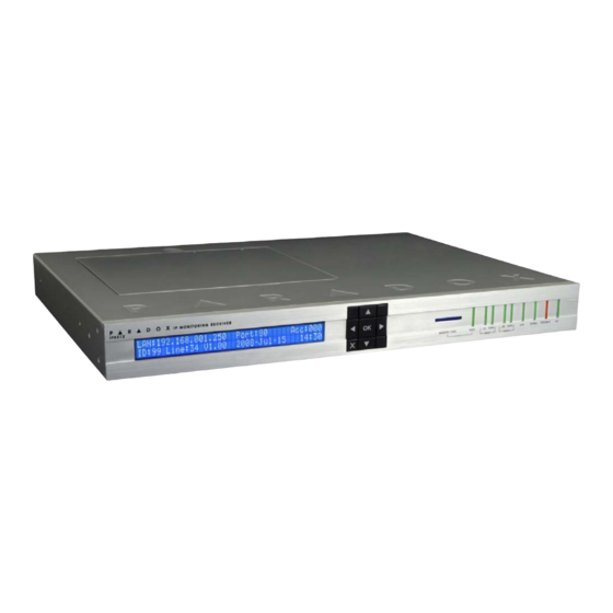
IPR512: GPRS/IP Monitoring Receiver V2.0
Quick Start
The following instructions explain the basic connections and programming required to get your Paradox IPR512 GPRS/IP
Monitoring Receiver up and running. They also guide the installer on how to register the Paradox reporting module (IP100 Internet
Module or PCS Module) to the receiver. For more detailed information, please refer to the IPR512 GPRS/IP Monitoring Receiver
Operations Manual.
Paradox Communicator Module
Serial
Paradox Control
Paradox Internet
Panel
Out of the Box (included):
•
Paradox IPR512 GPRS/IP Monitoring Receiver
•
2GB memory card
•
1.8m (6ft) power cable
•
3m (10ft) DB25 to DB9 serial cable for COM1
•
DB9 gender changer
•
Rack-mount kit (brackets and screws)
•
Desktop installation kit (rubber feet)
•
Removable connector for Input/Output Relay
Step 1: Connect COM1 (Automation Software)
Connect the receiver to a PC running the automation software. Connect the provided 3m (10ft) DB25 to DB9 cable between the
receiver's COM1 connector and a COM port on the PC, or on the PC's serial hub.
C
1
COM NO
COM
1
INPUT
OUTPUT
(PC)
TRIGGER
RELAY
Step 2: Connect COM2 (Optional: Serial printer/PC)
This step is optional. Connect the receiver to a serial printer or to a PC running RS232 serial communication software. The
receiver sends reported events in plain text format through COM2 (RS-232), which can be printed or viewed. Connect a serial
cable between the receiver's COM2 (DB9) connector and a COM port on the serial printer or PC (gender changer is included).
C
1
COM NO
COM
1
INPUT
OUTPUT
(PC)
TRIGGER
RELAY
IPR512-EQ03 10/2009
Figure 1: System Overview
(PCS Series)
Router
Module (IP100)
COM 2
LAN
WAN 1
WAN 2
(SERIAL OUT)
COM 2
LAN
WAN 1
WAN 2
(SERIAL OUT)
LAN
WAN1
WAN2
Routers
Paradox IPR512
GPRS/IP Monitoring Receiver
(IPR512)
Additional Items Required (not included)
•
CAT5 network cable for LAN and WAN1/WAN2
•
Optional: DB9 or DB25 serial cable (RS-232) for COM2
•
Router and computer on a network to access internal web page
interface (LAN)
•
Router on a network with internet access (WAN1) to receive
control panel report codes
P A R A D O X . C O M
P A R A D O X . C O M
IPR512 V2.0
Web Page
Interface
Automation
Software
COM1
COM2
Serial printer/
PC
I
O
Automation
Software
I
O
Serial printer/
PC
PARADOX.COM
Advertisement
Table of Contents

Subscribe to Our Youtube Channel
Related Manuals for Paradox IPR512


Summary of Contents for Paradox IPR512
-
Page 1: Quick Start
The following instructions explain the basic connections and programming required to get your Paradox IPR512 GPRS/IP Monitoring Receiver up and running. They also guide the installer on how to register the Paradox reporting module (IP100 Internet Module or PCS Module) to the receiver. For more detailed information, please refer to the IPR512 GPRS/IP Monitoring Receiver Operations Manual. -
Page 2: Step 5: Connect Power
Step 6: Insert Memory Card (Data Backup) Insert memory card (included) into the Memory Card slot. The IPR512 supports any external SD, SD/HC, or MMC memory card. The receiver backs up data automatically (receiver configuration and account information) 10 minutes after a change has been made in the database. - Page 3 Enter the username (default: admin) and password (default: admin) and press the Login button. The username cannot be changed, but you can change your password by clicking on Change Password option from the main menu. IPR512-EQ03 09/2009 Page 3 PARADOX.COM...
-
Page 4: Step 10: Configure The Receiver
The following lists only the minimum programming required to get the receiver up and running. For more detailed information on settings in the Web Page Interface, please refer to the IPR512 GPRS/IP Monitoring Receiver Operation Manual. 1) From the Main Menu, click Receiver Configuration. -
Page 5: Step 11: Event Configuration
Step 11: Event Configuration The Paradox reporting module will send a presence message (~100 bytes) at intervals defined by the Module Polling Time. If the receiver does not receive at least one presence message from the module within the Receiver Supervision Time, the receiver can report a communication loss to the Automation Software. -
Page 6: Step 12: Set Security Profile
This number is automatically generated by the system. NOTE: For the Receiver Supervision Time (item #5), Paradox recommends a minimum value of 1 minute. Also, the Module Polling Time (item #4) must be at least than half the Receiver Supervision Time (e.g., RST: 1 minute - MPT: 30 sec.) -
Page 7: Trouble Display
IPR512 GPRS/IP Monitoring Receiver Operations Manual. The next step is to register Paradox reporting modules to the receiver. No monitoring station operator action is required to register a module. Registration is initiated by the installer upon installation of the module. However, the monitoring station must provide the installer with the following information that is entered by the installer. -
Page 8: Installer Instructions
[2991] © 2009 Paradox Security Systems Ltd. All rights reserved. Specifications may change without prior notice. One or more of the following US patents may apply: 7046142, 6215399, 6111256, 6104319, 5920259, 5886632, 5721542, 5287111, 5119069, 5077549 and RE39406 and other pending patents may apply. Canadian and international patents may also apply. For the latest information on products approvals, such as UL and CE, please visit www.paradox.com.
Need help?
Do you have a question about the IPR512 and is the answer not in the manual?
Questions and answers