Table of Contents
Advertisement
Quick Links
Instruction Manual
EMS-01 V5.0 (24V DC)
Multifunction Energy Meter
Introduction
PARAMETERS
PAGE
1
2
3
4
BASIC THD TOTAL IMPORT EXPORT
V
*
, V
*
PP
PN
I
*
, RPM, Angle
*
Device ID
PF
*
Hz
KW*
KVAR*
KVA*
Neutral Current**
Voltage (%) ***
Current (%) ***
KWh
KVrhC
KVrhI
KVAh
LOAD HOURS
* :
R,Y,B,Total
**: Neutral current can be measured for unbalanced current
loads which are all 120° out of phase.
***: R , Y, B
Box Accessories
One (1) EMS-01(24V DC) digital meter
One (1) Instruction Manual
One (1) test report & calibration certificate for energy meter
Side Anchor (2 nos.)
CREATED ON: April 28, 2016
Safety Precautions
Read and follow all the safety precautions and instructions before
installing and working with the equipment.
HAZARD OF ELECTRIC SHOCK, EXPLOSION OR ARC FLASH
• Apply appropriate personal protective equipment(PPE) and follow safety
work practices
• Only qualified electrical workers should install this equipment. Such work
should be performed only after reading this entire set of instructions.
• If the equipment is not used in the manner specified by the manufacturer,
the protection provided by the equipment may be impaired.
• NEVER work alone.
• Turn OFF all power supplying the energy meter and the equipment in
EAPL
which it is installed before working on it.
• The successful operation of this equipment depends upon proper
handling, installation and operation. Neglecting fundamental installation
requirements may lead to personal injury as well as damage to electrical
equipment or other property.
• NEVER bypass external fusing.
• NEVER short the secondary of PT
• NEVER open circuit a CT; use the shorting block to short circuit the leads of
5
6
7
8
CT before removing the connection from energy meter.
OLD
OLD
OLD
• Before performing Dielectric or Megger testing on any equipment in which
TOTAL
IMPORT
EXPORT
the energy meter is installed, disconnect all the input and output wires to
the energy meter. High voltage testing may damage electronic
components contained in the energy meter.
• The energy meter should be installed in a suitable electrical enclosure.
Failure to follow these instructions will result in death or serious injury.
• EAPL is not responsible for any consequential damages arising out of use of
our products, though the technology is cautiously chosen and
implemented like any other well designed good electric meter.
Installation
Connecting cable recommendations
Voltage circuit
Current circuit
Tools and Fasteners
Kindly use star – type screw driver for tightening the screws.
NOTE:
Installation should include a disconnecting device, like switch or
circuit breaker, with clear ON/OFF markings, to turn-off the auxiliary
supply (control power).The disconnecting device should be within the
reach of the equipment and the operator.
!
DANGER
Insulation rating
Current rating
>600 VAC
>0.1A
>7.5A/2.5mm
2
/
>600 VAC
14AWG minimum
Dimension
Note: All Dimensions are in mm.
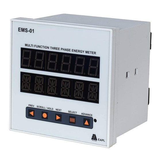
Front Panel
1. Top Display Window
2. Bottom Display Window
3. Previous button
4. Scroll/Hold button
5. Next button
6. Select button
7. Advance button
8. Pulse Constant
Rear Panel
OD RE KN 540011 REV 02/28-04-16
Page 1 of 2
Advertisement
Table of Contents

Related Manuals for EAPL EMS-01


Summary of Contents for EAPL EMS-01
-
Page 1: Safety Precautions
Failure to follow these instructions will result in death or serious injury. 5. Next button • EAPL is not responsible for any consequential damages arising out of use of 6. Select button our products, though the technology is cautiously chosen and 7. -
Page 2: Technical Specification
Disposition Program Factory 1, 2, 3, 4 : R, Y, B, N Function Range Once the product life is over, you may send back the unit to EAPL for 5 ,6 : No connection setting page disposition : A,B (RS 485Communication port)
Need help?
Do you have a question about the EMS-01 and is the answer not in the manual?
Questions and answers
How to program it
To program the EAPL EMS-01:
1. Switch to PROGRAM Mode.
2. Use the keys:
- PREVIOUS Key: Program previous parameters.
- NEXT Key: Program next parameters.
3. Use the PROGRAM Mode to:
- Increase parameter values by one.
- Set input current range (1A to 5A, up to 200%).
- Configure input voltage range and frequency (415 VAC ±20%, 50 Hz ±2%).
4. Save settings automatically; energy and display status are saved in case of power failure.
RS-485 MODBUS RTU communication can also be configured if needed.
This answer is automatically generated
What is the password
The default password for the EAPL EMS-01 is 1000, and it can be set within the range of 0001 to 9999.
This answer is automatically generated