Advertisement
Quick Links
EAPL
PVMD V3.0
Model
INSTRUCTION MANUAL
PHASE AND VOLTAGE
MONITORING DEVICE
www.eaplindia.com
DIMENSION
CONNECTIONS
Accessories:
unit with button flap in place.
•
Panel locking Clamps with screws (Qty:
•
2 nos each)
Instruction Manual
•
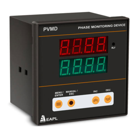
FRONT VIEW
Self powered device, Displays 3 Phase voltages (L-N& L-L)
during healthy condition.
Monitors the Phase sequence, Phase failure, Phase
unbalance, over voltage and under voltage in 3 Phase 4 wire
system.
Short 5&6 for program lock.
1.
Top Display Window
2.
Bottom Display Window
3.
MENU/ENTER Button
4.
INC Button
5.
DEC Button
6.
MANUAL / ESC Button
7.
RLY
REAR VIEW
1, 2, 3, 4 : R, Y, B, N
5,6
: Program Lock
6,7
: AUTO RST
8
: Common Relay
15: NO 16: NC
FUNCTION
PROGRAMMING
Top
Press "MENU"
Press INC/DEC key to set
Display
button, Bottom
the values of parameters .
Shows
Display shows the
following.
Nominal voltages
415
"nUOL"
Over Voltage.
05
"OUOL"
Range: 5 to 100V
Under voltage.
05
"UUOL"
Range: 5 to 100V
Phase Unbalance.
20
" PUbl"
Range: P 1-20%
Trip delay OverVoltage.
5
" tdOV"
Range: 1 - 250sec
Trip delay Undervoltage.
5
" tdUV"
Range: 1 - 250sec
Trip delay Unbalance.
5
"tdUb"
Range: 1 – 250sec
Bypass Over Voltage
bYPS
"OVL Y/n"
Bypass Under Voltage
bYPS
"UVL Y/n"
Bypass Phase Unbalance
bYPS
"UBL Y/n"
When rLY 'Y ' is selected
relay will be ON i.e. ( C to
NO) . When fault occurs
relay goes OFF i.e. (C to
NC).
CntL
"rLY Y/n"
When rLY 'n' is selected
relay will be OFF i.e.(C to
NC). When fault occurs
relay goes ON i.e. (C to NO
DOC NO: OD RE YN 21005 0 Rev No: 05
RUN MODE
A power ON delay is seen. During this state the
relay will be in NC condition and Relay status
LED will be Off.
Top window will display voltages and Bottom
window will display respective parameters.
In manual mode, the relay will energize and
change over takes place to NO and relay status
LED comes ON only when the user presses the
ESC/Manual button. Till such time the relay
status LED will be OFF.
In Auto mode ( i.e short 6 & 7 terminals), the
relay will energize, change over takes place to
NO and Relay status LED will come ON
immediately after the power ON time is over.
When fault occurs refer the following table:
Parameters
Top
Bottom
display
display
OVER VOLTAGE
Err
OUOL
UNDER VOLTAGE
Err
UUOL
PHASE UNBALANCE
Phs
UbAL
PHASE REVERSE
Phs
rEU
R PHASE FAIL
FAIL
P-r
Y PHASE FAIL
FAIL
P-Y
B B PHASE FAIL
FAIL
P-b
PHASE UNBALANCE CONDITION:
To set unbalance condition for 20% .
Set 20 in unit (PUbL=20 as shown in the table).
If RY=350V, YB=450V, BY=319V in the load.
Fault is created in the unit , upper displays
shows "Phs" and lower shows
"UbAL".
Calculations are as follows
Set nVOL=415V , PUbL=20% in the unit.
Vry=350V, Vyb=450V, Vbr=319V , Vavg= 373V
Vry -Vavg=23V, Vyb -Vavg=77V,Vb-Vavg=54V
Phase unbalance= (Maximum deviation / Vavg) * 100 = 20 %
.
Dtd: 16/03/2015
Page 1 of 2
Advertisement

Related Manuals for EAPL PVMD V3.0


Summary of Contents for EAPL PVMD V3.0
- Page 1 FRONT VIEW FUNCTION RUN MODE EAPL A power ON delay is seen. During this state the PVMD V3.0 Model relay will be in NC condition and Relay status Self powered device, Displays 3 Phase voltages (L-N& L-L) LED will be Off.
- Page 2 3) Relay is not tripped EAPL is not responsible for any consequential Go to the program mode and check the damages arising out of use of our products, though “rly”option...
- Page 3 SIGN & DATE PREPARED: V.N.Sudhamani CHECKED: B. S Sridevi APPROVED: Kalavati Shanbhag 14/03/2015 16/03/2015 16/03/2015 DOC NO: OD RE YN 21005 0 Dtd: 19/07/13...
Need help?
Do you have a question about the PVMD V3.0 and is the answer not in the manual?
Questions and answers