Table of Contents
Advertisement
Alarm Controller
Fire and CO
Model: Ei450
Instruction Manual
Read and retain carefully for as long as the product is being used. It contains vital information on the operation and installation of your
Alarm Controller. The booklet should be regarded as part of the product.
If you are just installing the unit, the booklet must be given to the householder. The booklet is to be given to any subsequent user.
Advertisement
Table of Contents

Related Manuals for Aico RadioLINK Ei450


Summary of Contents for Aico RadioLINK Ei450
- Page 1 Alarm Controller Fire and CO Model: Ei450 Instruction Manual Read and retain carefully for as long as the product is being used. It contains vital information on the operation and installation of your Alarm Controller. The booklet should be regarded as part of the product. If you are just installing the unit, the booklet must be given to the householder.
-
Page 2: Table Of Contents
Contents Page 1. Overview ..............................2. Installation ............................. 3. House Coding ............................4. Operation ............................... 5. Guarantee ............................. 6. Troubleshooting the RadioLINK ..................... 7. Technical Specification ........................8. Getting your Alarm Controller Serviced ..................9. System Diagnostics ..........................10. Contact Us ............................ -
Page 3: Overview
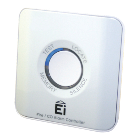
1. Overview Congratulations on purchasing the single button Alarm Controller for RadioLINK Fire and Carbon Monoxide (CO) Alarm systems. The Alarm Controller tests and controls Fire, CO and combined (Fire + CO) RadioLINK Alarm systems. Alarm Controller functionality Function Description Test All the Alarms can be tested from a centralised location Locate... - Page 4 Low Battery Indicator Indicator Fire Indicator House Code Button Light Segments (4) On / Off Switch Test / Control Button System Diagnostics Mode Button Fire / CO Alarm Controller Front View of Controller Rear View of Controller...
- Page 5 Wireless Smoke Alarm System Wireless Smoke & Carbon Monoxide Alarm System RF Smoke Alarm RF Smoke Alarm RF CO Alarm RF Smoke Alarm Alarm Controller Universal Interface Alarm Controller Universal Interface RF Smoke Alarm RF Smoke Alarm Model No. - Alarms Comment Ei140RC, Ei160RC &...
-
Page 6: Installation
Typical System Layout Install the Alarm Controller mounting plate at an accessible point on the wall 1.4m +/- 0.2m from floor level. Consider an alternative location if the controller will be operated by a disabled person. Also consider security and chose a location where it will not be accidently or otherwise operated. - Page 7 Power up sequence FIRE, BATTERY & CO indicators flash Each individual segment lights up red Each individual segment lights blue Each individual segment lights green After power up sequence all lights will go off to indicate standby mode.
-
Page 8: House Coding
3. House Coding It is essential to House Code the Alarm Controller to all the other RadioLINK Alarms and devices in the system to ensure they will not communicate with nearby systems. Failure to house code the system may also result in a system malfunction. WARNING Press and hold the House Code button (H CODE) on the back of the controller until all segments light up blue, then release. - Page 9 Return to the Alarm Controller and check that all segments are flashing blue. The number of flashes should equal the number of RadioLINK Alarms and devices in the system. A system with 3 x Smoke Alarms, 1 x CO alarm and 1 x Alarm Controller will result in 5 blue flashes.
- Page 10 To complete the commissioning, the system must exit house code mode. The units will automatically exit house code after 30 minutes. Once coded the system will not communicate with any other RadioLINK Alarms and devices outside the house coded group. To manually exit house code press the house code (H CODE) button on the back of the Alarm Controller.
- Page 11 Slide the Alarm Controller onto the mounting base on the wall. Fire / CO Alarm Controller Check that the RadioLINK system is working by pressing the button on the Alarm Controller until the TEST segment lights blue. This indicates a RadioLINK test signal has been activated.
- Page 12 Reset the house code Sometimes in order to resolve an RF communication issue, e.g. Alarms have to be relocated, it may be necessary to reset and house code all RadioLINK Alarms and devices in the system again. To reset the Alarm Controller press and hold the house code button. All segments will flash blue briefly and then go solid.
-
Page 13: Operation
4. Operation Frequent testing of the system is advised to ensure its continued and safe operation. Guidelines and best practices for testing are as follows: 1. After the system is installed. 2. Once weekly thereafter. WARNING 3. After prolonged absence from the dwelling (e.g. after holiday period). 4. - Page 14 Walk round test (optional) Remove the Alarm Controller from its cradle. If the unit has been tamper proofed you will need to release the latch with Fire / CO Alarm Controller a screwdriver. With the Alarm Controller in your hand press and hold the Fire / CO Alarm Controller button.
- Page 15 Locate the source Alarm(s) If the FIRE indicator is lighting and there is no obvious fire, press the button. The LOCATE segment will change from red to blue. After a 10 to 40 seconds period, all the Alarms in the system will Fire / CO Alarm Controller Fire / CO Alarm Controller stop sounding except the source Alarm(s).
-
Page 16: Guarantee
standby mode without being noticed. Should this happen the Ei450 will continue to flash either the Fire or CO icon rapidly for a two minute period. If the system has been activated by a CO alarm the Ei450 will continue to flash the CO Icon for a 24 hour period but at a lower rate of 1 flash every 60 seconds. -
Page 17: Troubleshooting The Radiolink
6. Troubleshooting the RadioLINK If, when checking the RadioLINK interconnection, some of the Alarms do not respond to the Alarm Controller remote control test, then: (i) Ensure the Alarm Controller has been activated correctly. Check that the power on procedure operates as described in the ‘Installation’... -
Page 18: Technical Specification
7. Technical Specification Supply Voltage Powered for life Lithium battery Battery Capacity 1600 mAh RF Frequency 868.499Mhz Temperature Specification C to 40 C (Cat 3) Humidity 15% - 95% (Non Condensing) Receiver Category Cat 2 RF Performance EN 300-220-2 EMC Performance EN 301 489-1, EN 301 489-3 Safety Testing EN 60065... -
Page 19: Getting Your Alarm Controller Serviced
8. Getting the Alarm Controller serviced If your Alarm Controller fails to work after you have carefully read all the instructions and checked that the unit has been installed correctly contact Customer Assistance at the nearest address given at the end of this booklet. -
Page 20: System Diagnostics
9. System Diagnostics The system diagnostic mode does not work with all RadioLINK alarms and accessories. If the system diagnostic features are required for your installation please contact technical support to verify that all your RadioLINK components are compatible with these features. WARNING The System Diagnostic features are intended to assist professional installation and maintenance personal to install, commission and maintain the RadioLINK Fire and CO systems utilising the Alarm... - Page 21 To enter the system diagnostic mode use a small screwdriver to press and release the MODE button on the back of the unit. All segments will flash green almost immediately. Quickly release the MODE button, the system diagnostic mode is now activated. Two minute - Long test On entering the system diagnostic mode the TEST segment will flash green inviting you to press the button.
- Page 22 Check Alarm memory RadioLINK enabled Smoke and CO alarms have the ability to record if they have been previously activated and store it in their memory. This can then be recalled via the diagnostic mode. On entering the system diagnostics mode, if an alarm memory has been set, the MEMORY Fire / CO Alarm Controller segment will flash green and the Fire or CO indicator will flash.
- Page 23 Erase Alarm memory Press and hold the MODE button on the back of the unit. The green segments will light up. When these segments start flashing, release the button. Press the button on the alarm controller to test the system. The locate alarm memory is now cleared.
-
Page 24: Contact Us
To access this website product page you may use your smart phone to activate the QR code or you can go to this page on our website www.eielectronics.com/articles/ei450-memory-id-products.html Aico Ltd Ei Electronics Mile End Business Park,...
Need help?
Do you have a question about the RadioLINK Ei450 and is the answer not in the manual?
Questions and answers