
Related Manuals for Plymovent WALLPRO


Summary of Contents for Plymovent WALLPRO
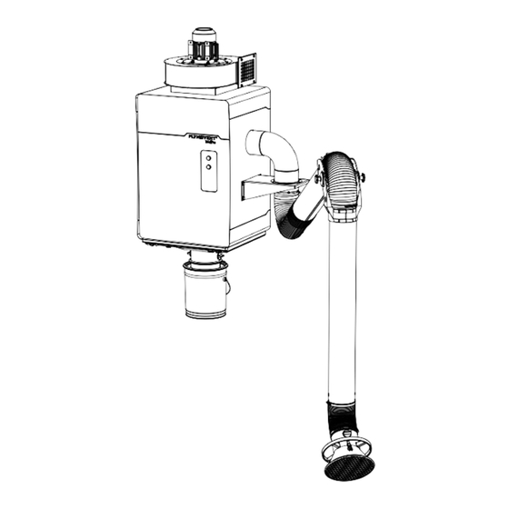
- Page 1 EN Stationary filter unit WALLPRO Installation and user manual www.plymovent.com...
- Page 2 To improve comprehension for people whose first language is not English, we have written parts of this manual in Simplified Technical English (STE). STE is a controlled language originally developed for aerospace industry maintenance manuals. It offers a carefully limited and standardized subset of English, along with specific writing rules. 000115682/151018/0 WallPro...
-
Page 3: Table Of Contents
TABLE OF CONTENTS ENGLISH Page NEDERLANDS Pag. DEUTSCH Seite Preface 1. Introduction 2. Product description 3. Safety instructions 4. Installation 5. Use 6. Maintenance 7. Troubleshooting 8. Spare parts 9. Electrical diagram 10. Disposal CE declaration FRANÇAIS Page ESPAÑOL Pág. SVENSKA Sida ITALIANO Pag. 000115682/151018/0 WallPro... -
Page 4: Preface
Using this manual This manual is intended to be used as a work of reference for General description professional, well trained and authorised users to be able to safely install, use, maintain and repair the product mentioned The WallPro is a stationary welding fume filter including one on the cover of this document. (WallPro Single) or two (WallPro Double) extraction arms and a fan. The highly efficient filter cartridge is automatically cleaned Pictograms and symbols by the integrated RamAir™ pulse amplifier, based on external The following pictograms and symbols are used in this manual: compressed air supply. The extraction arm(s) can be mounted directly to the filter unit Suggestions and recommendations to simplify (“DM” types) or at an external position (“EM” types). carrying out tasks and actions. The WallPro Basic and WallPro Basic PowerPlus are filter units ATTENTION with fan but without extraction arm(s). They are suitable for A remark with additional information for the user. A connection to an external device. remark brings possible problems to the user’s attention. 1.2.1 Intensity of use CAUTION! Procedures, if not carried out with the necessary The WallPro Single “PowerPlus” ‒ that combines the largest caution, could damage the product, the workshop or arm diameter with an extra powerful fan ‒ is particularly the environment. suitable for heavy duty applications with large quantities of WARNING! -
Page 5: Product Description
- LL-5.5/24 | Manual on/off switch on the hood, incl. LED 1,5 kW (2 HP) 2,2 kW (3 HP) • 60 Hz working light Motor design: • 50 Hz Technical specifications • 60 Hz NEMA NEMA 1.4.1 Filter unit Energy efficiency: • 50 Hz WallPro Single | Double • 60 Hz premium premium Material (housing) electro-zinc coated steel Fan outlet (via Ø 250 mm Ø 250 mm transition) Weight 125 kg (excl. arm and fan) Noise level 75 dB(A) 76 dB(A) -
Page 6: Safety Instructions
Users - The use of this product is exclusively reserved to authorised, trained and qualified users. Temporary personnel and personnel in training can only use the product under supervision and responsibility of skilled engineers. - Stay alert and keep your attention to your work. Do not use the product when you are under the influence of drugs, alcohol or medicine. - The product is not to be used by children or persons with reduced physical, sensory or mental capabilities, or lack of experience and knowledge, unless they have been given Fig. 2.1 Main components and elements supervision or instruction. - Children must be supervised not to play with the product. Operation Intended use The WallPro works in accordance with the recirculation The product has been designed exclusively for extracting and principle. Welding fume is extracted through the hood of the filtering gases and particles which are released during the connected extraction arm(s) by the fan. The polluted air most common welding processes. Using the product for other passes the deflector plate(s) behind the inlet opening(s) and purposes is considered contrary to its intended use. The is cleaned by the filter cartridge. The welding fume particles manufacturer accepts no liability for any damage or injury are collected at the outside of the filter cartridge. The cleaned resulting from such use. The product has been built in air is returned in the workshop through the outlet of the fan or accordance with state-of-the-art standards and recognised exhausted to the atmosphere via an outlet duct. safety regulations. Only use this product when in technically perfect condition in accordance with its intended use and the instructions explained in the user manual. -
Page 7: Installation
- type H05VV-F (PVC, standard cable); or: - Check the working environment. Do not allow unauthorised - type H05RN-F (rubber, for heavy duty, e.g. when part of persons to enter the working environment. the cable is on the floor) - Protect the product against water and humidity. - Quick disconnect coupling with a male G 3/8” thread - Make sure the room is always sufficiently ventilated; this - Compressed air hose applies especially to confined spaces. - Make sure that the workshop, in the vicinity of the product, WallPro type “EM” only contains sufficient approved fire extinguishers (suitable for - Wall mounting hardware for the arm bracket(s) fire classes ABC). - Ducting Ø 160 mm (6 in.) / Ø 200 mm (8 in.) between the - Do not leave any tools or other objects in or on the unit. filter unit and the arm bracket(s) - The welding current return circuit between the workpiece and the welding machine has a low resistance. Thus avoid connection between the workpiece and the WallPro, so that there is no possibility of the welding current flowing back to the welding machine via the protective earth conductor of 8. The type of hardware depends on the wall type... -
Page 8: Fig. 4.2
WallPro “UL” types (60Hz versions) only Control box: CE marking - Components necessary for electrical installation according to Control box: UL certified UL and federal, state or local wiring regulations Option A number of installation steps are only applicable to one or In case of a dustbin extension set: more specific configurations. These are indicated at the - duct Ø 200 mm or 8 in. beginning of a certain paragraph. The grey/empty cells are universal. Unpacking Some examples: Make sure that the product is complete. The package contains: In case of: Applies to all Filter unit “DM” types - Filter unit (without side panels), incl. 10 m cable - Wall bracket - Dustbin set Applies to all... -
Page 9: Fig. 4.3
In case of a LL-5.5/24 | Manual on/off switch on the hood, incl. LED working light (option) • Install the cable gland M16 + nut M16 (C). If not: • Install the screw plug M16 + nut M16 (D). 16. By the use of SealApplicator you can slightly shift the side panel to get the right position. After approx. 60 seconds the lubricant is dry so you cannot shift anymore. 14. In case of a WallPro Double you must install a reinforcement plate on both 17. After approx. 60 seconds SealApplicator lubricant loses its functions and you sides cannot shift anymore. 15. On the left or right side of the filter unit 18. You must remove them later on to install the arm bracket. 000115682/151018/0 WallPro EN - 8... -
Page 10: If Applicable
Refer to Fig. III on page 21 for an overview of the possible outlet directions. 4.3.4 Arm bracket To install the fan, do the following. In case of: Fig. 4.7 • Put adhesive rubber strip (A) around the inlet opening on top of the filter unit. Make sure that the strip does not entirely cover the holes. ATTENTION! • Disassemble the service panel (refer to Fig. 2.1F). Make sure that you have installed the reinforcement plate behind the side panel; refer to paragraph 4.3.1. Fig. 4.6 • Install the arm bracket on the filter unit with 4 bolts M12x30 and washers M12. 19. WallPro Single: blind side panel | WallPro “EM”: side panel with inlet flange + non-return valve Fig. 4.7 Adhesive rubber strip 20. The ones you used to align the side panel in step 4.3.3 000115682/151018/0 WallPro EN - 9... - Page 11 • Secure the unit to the wall bracket with the bolts M10x30, locknuts M10 and washers M10 (C). Fig. 4.8 Positioning studs Compressed air connection (filter unit) ATTENTION The compressed air must be dry and oil-free according to ISO 8573-3 class 6. Fig. 4.9 • Install a quick disconnect coupling with a male G 3/8” thread to the female fitting (A) on the unit. • Install a compressed air supply hose to this coupling. • Connect the air hoses in the connectors + and − (B+C). Fig. 4.10 Mounting of the wall bracket 23. In case of an “EM” type, the installation height is less critical, since the extraction arms are mounted separately from the filter unit. However, to avoid 21. You do not need these four bolts anymore. The other two bolts remain unused bends (=pressure drop) in the ducting, we recommend to install the filter unit but must stay in the inlet flange at the indicated height and to connect the arms as close as possible to the 22. The different colours simplify correct connection to the control box filter unit. 000115682/151018/0 WallPro EN - 10...
- Page 12 • “DM” types only: Feed the cable through the reinforcement Wire # Colour Connection plate (A). • Remove the blind plug (C) from the nearest (left or right) cable gland (B), just below the indicator panel. black • Feed the cable through the cable gland (B) inside the unit. • Tighten the cable gland. grey blue Fig. 4.13 Cable connection inside indicator panel ATTENTION! Before you proceed, make sure that all cable glands are fully tightened, to prevent leakage of dust. 4.7.2 Inlet ducting In case of: 24. In case of a WallPro Double: use the left cable gland for the left arm and vice versa 25. Manual on/off switch on the hood, incl. LED working light 000115682/151018/0 WallPro EN - 11...
- Page 13 • Install the dustbin assembly (C) to the hopper (A) with the Control box supplied duct clamp (B). • Turn the rotary knob (D) in vertical position to open the shut-off valve. 4.9.1 Connections Refer to the separately supplied electrical diagram for the electric connections. Refer to paragraph 4.1.1 for the required cable specifications. In case of: Components necessary for electrical installation according to UL and federal, state or local wiring regulations are not included and must be sourced locally. Fig. 4.15 Mounting of the dustbin Fig. 4.20 • Install the control box at an appropriate position. • Connect the control box to the fan (B). • Connect the control cable (C) from the filter unit to the control box (refer to Fig. 4.9E). 26. Inlet flange + non-return valve (assembly) 27. In case of 60Hz configurations with an imperial duct size (Ø 6 in. or Ø 8 in.) 28. Ø 160 mm / 6 in. or Ø 200 mm / 8 in., depending on the inlet diameter 000115682/151018/0 WallPro EN - 12...
- Page 14 Fig. 4.20 Control box FILTRO OBSTRUIDO As the manufacturer does not know in which configuration the WallPro Basic is installed, you must use these pressure setting values FILTER CLEANING as a guideline only. The optimum pressure setting will be a matter of FILTERREINIGING...
-
Page 15: Use
WARNING! Silencer Recirculation Fire hazard! Do not use the product for polishing applications in combination with grinding, welding or any other application that generate sparks. Refer to chapter 3 / Safety instructions / Use. Outlet duct Exhaust to atmosphere Control panel The WallPro has a separate control box. Controls and 4.10.1 Fan outlet transition indicators: Fig. 4.23 Fig. 5.1 • Determine the desired outlet configuration. POWER ON | white LED that indicates that the control box is connected to the mains and that the power is on In case of direct recirculation of the air, the outlet transition is FILTER CLOGGED | red LED that indicates that it is redundant. necessary to replace the filter cartridge Main switch | to (de-)energize the entire unit... -
Page 16: Maintenance
• Make sure that the shut-off damper inside the extraction you observe the necessary caution and carry out the arm is open (refer to Fig. VIII on page 23). maintenance at regular intervals, any problems occurring will • Make sure that the main switch (C) is on. be detected and corrected before they lead to a total • Push the START/STOP FAN (E) button to activate the fan breakdown. • Start welding. • When the welding position changes, move the hood to the WARNING correct position in relation to the weld. Overdue maintenance can cause fire. WARNING To keep the welding fume away from the breathing The indicated maintenance intervals can vary depending on zone of the welder, make sure that all fume is the specific working and ambient conditions. Therefore we extracted through the hood. recommend to thoroughly inspect the complete product once every year beside the indicated periodic maintenance. For this • Put the unit off approx. 20 seconds after you have finished purpose contact your supplier. welding. 32. Options to activate the fan: on/off switch on the hood of the extraction arm or automatically via a welding cable sensor (WCS-WP) 000115682/151018/0 WallPro EN - 15... -
Page 17: Refer To Paragraph 6.4
Scan the QR code to watch a short demo about filter replacement. Fig. 6.2 Plastic bag To guarantee dust-free filter removal, you must loosen the star knobs of the hopper and the filter cartridge via the outside of the plastic bag. This means that you do not touch the knobs Fig. 6.1 directly. • De-energize the unit. • Turn the rotary knob (A) in horizontal position to close the Fig. 6.3 shut-off valve. • Loosen the 2 star knobs (D) and release the hopper (C). • Loosen the quick release clamp (F) and remove the dustbin (G). • Move the hopper in fully vertical position. Lock the hopper with the lid stays (B). • Loosen the duct clamp (D) and remove the flange (E). • Loosen the star knob (A) and carefully lower the filter If there is enough space behind the filter unit to cartridge into the plastic bag. turn the hopper including flange 90°, it is not • Lift the plastic bag, turn it around and seal it with a cable necessary to remove the flange. tie. 000115682/151018/0 WallPro EN - 16... -
Page 18: Troubleshooting
To empty the dustbin, do the following. The mains cord Repair or replace is defective the mains cord Fig. 6.4 Loose contacts Repair the contacts • Option: de-energize the unit. Motor defective Repair or replace • Turn the rotary knob (A) in horizontal position to close the the motor shut-off valve. • Loosen the quick release clamp (B) and remove the dustbin START/STOP Replace the green (C). FAN button button • Empty the dustbin. (green) is • Install the dustbin and fasten the quick release clamp. defective 33. The washer is supplied with the new filter cartridge 34. The star knob is attached to a rope to prevent loss 000115682/151018/0 WallPro EN - 17... -
Page 19: Spare Parts
Disposal from the insufficient rubber strip is adhesive rubber hopper damaged or strip Dispose of the pollutants and dust, together with the used worn filters, in a professional manner in accordance with federal, The star knobs Fully tighten the state or local regulations. of the hopper star knobs are not fully tightended Dust leakage The non- Non-return Clean the non- from the return valve valve cannot return valve extraction is not close properly functioning Mechanical Replace the properly failure non-return valve 000115682/151018/0 WallPro EN - 18... -
Page 20: Ce Declaration
CE DECLARATION CE declaration of conformity for machinery We, Plymovent Manufacturing B.V., Koraalstraat 9, 1812 RK Alkmaar, Netherlands, herewith declare, on our own responsibility, that the product: - WallPro which this declaration refers to, is in accordance with the conditions of the following Directives: - Machine Directive 2006/42 EC - EMC 2014/30 EU - LVD 2014/35 EU - ErP Directive 2009/125 EC - W3 compliant (EN-ISO 15012-1:2013) Signature: Name: M.S.J. Ligthart Position: Product Manager Date of issue: 1st October 2018 For a CE declaration of the fan, refer to the corresponding manual. - Page 21 Fig. I Dimensions Dimensions Dimensiones Afmetingen Dimensioni Abmessungen Dimensões Dimensions Wymiary Control box inch 14.3 13.1 10.9 WallPro inch 27.6 Single 1991 78.4 Basic Single PowerPlus Basic PowerPlus 2059 81.1 Double 1236 48.7 38.4 30.1 + KUA-160 Ø 160 Ø 6 + KUA-200 Ø 200 Ø 8 1040 40.9...
- Page 22 Fig. II Working range WallPro Single WallPro Double Working range Max. distance Max. angle Mounting position E Wall mounting On a stanchion or similar Werkbereik Max. afstand Max. hoek Wandmontage Bereich Portée Alcance de trabajo Raggio di lavoro Zakres pracy KUA-160/3H KUA-160/3H KUA-200/3H KUA-160/4H KUA-160/4H KUA-200/3H KUA-200/4H KUA-200/4H Fig. III Outlet direction of the fan FUA-3000 FUA-4700 Possible outlet directions of the fan Mogelijke uitblaasrichtingen van de ventilator 000115682/151018/0 WallPro...
- Page 23 Fig. IV Configurations + mounting material WallPro WallPro + SET 1 + SET 6 Double Single GEN. MOUNTING MAT. kit 1 GEN. MOUNTING MAT. kit 1 Single Double Basic + kit 2 + kit 2 + kit 2 + kit 2 + kit 2...
- Page 24 Fig. VII Positioning of the extraction arm (⅛ in.) Clearance between side panel and housing (top + 400-800 mm bottom) 400-800 mm (16-32 in.) (16-32 in.) Positioning of the extraction arm Positionering van de afzuigarm Positionierung des Absaugarms Fig. VI Installation height Positionnement du bras d’aspiration Posicionamiento del brazo de aspiración Posizionamento del braccio aspirante Ustawienie ramienia odciągowego Fig. VIII Shut-off valve inch 22.05 2,25 - 2,55 7.5 - 8.5 0.60 Shut-off & control valve 0.50 11.8 Recommended installation height (E) + hole pattern Aanbevolen installatiehoogte (E) + gatenpatroon Empfohlene Installationshöhe (E) + Bohrmuster Hauteur recommandée d’installation (E) + configuration des trous Altura de instalación recomendada (E) + diseño de agujeros 000115682/151018/0 WallPro...
- Page 25 Fig. IX Exploded view WallPro 0000100306 | 50Hz 0000100308 | 50Hz 0000102923 | 60Hz 0000102925 | 60Hz 0000102926 | 60Hz 0000103156 | 60Hz 0040900010 0000115654 7900030800 0000117120 0000117119 0000102411 0000118185 0000117546 0000118194 0000117900 0000117872 0000117901 0000117871 0000115683 0000117875 Exploded view filter unit (WallPro) Exploded view filterunit (WallPro) Explosionszeichnung Filtereinheit (WallPro) Vue éclatée de l’unité de filtration (WallPro) Vista de despiece unidad de filtración (WallPro) Visa esplosa unità filtrante (WallPro)
- Page 26 WallPro EN | Spare parts NL | Reserveonderdelen DE | Ersatzteile 0000100306 FUA-3000 (IEC); 400V/3ph/50Hz FUA-3000 (IEC); 400V/3ph/50Hz FUA-3000 (IEC); 400V/3ph/50Hz 0000100308 FUA-4700 (IEC); 400V/3ph/50Hz FUA-4700 (IEC); 400V/3ph/50Hz FUA-4700 (IEC); 400V/3ph/50Hz 0000102411 Drain valve ½ inch Aftapkraan ½ inch Ablassventil ½ Inch 0000102923 FUA-3000 (NEMA); 208-230/460V/3ph/60Hz FUA-3000 (NEMA); 208-230/460V/3ph/60Hz FUA-3000 (NEMA); 208-230/460V/3ph/60Hz 0000102925 FUA-4700 (NEMA); 208-230/460V/3ph/60Hz FUA-4700 (NEMA); 208-230/460V/3ph/60Hz FUA-4700 (NEMA); 208-230/460V/3ph/60Hz 0000102926 FUA-4700 (NEMA); 575V/3ph/60Hz FUA-4700 (NEMA); 575V/3ph/60Hz FUA-4700 (NEMA); 575V/3ph/60Hz 0000103156 FUA-3000 (NEMA); 575V/3ph/60Hz FUA-3000 (NEMA); 575V/3ph/60Hz FUA-3000 (NEMA); 575V/3ph/60Hz 0000115654 NRV-200 / Non-return valve Ø 200 mm...
- Page 27 Fig. X Exploded view control box 0000117870 0000117120 0000117873 0000117874 0000117905 0000100613 0000101409 0000101409 0000102289 0000101413 0000117868 | CE 0000117869 0000102287 0000118192 | UL 0000102288 0000117133 0000117134 0040900200 000115682/151018/0 WallPro...
- Page 28 0000102289 Relay MC2A Relais MC2A Relais MC2A 0000117133 Thermal relay NTR-2,2-3,2A Thermisch relais NTR-2,2-3,2A Thermisches Relais NTR-2,2-3,2A 0000117134 Thermal relay NTR-7,5-10,5A Thermisch relais NTR-7,5-10,5A Thermisches Relais NTR-7,5-10,5A 0000117868 Differential pressure switch 6-50 mbar + Drukverschilschakelaar 6-50 mbar + Differenzdruckschalter 6-50 mbar + sticker scale 50Hz sticker schaal 50Hz Aufkleber Skala 50Hz 0000117869 PC board incl. software WallPro Printplaat incl. software WallPro Leiterplatte inkl. Software WallPro 0000117870 Pilot light white Controlelamp wit Kontrolllampe weiß 0000117873 Push button with blue LED Drukknop met blauwe LED Druckknopf mit blauer LED 0000117874 Stay-push button with green LED Drukknop met groene LED Druckknopf mit grüner LED 0000117905 Fuse 5x20 (500 mA) Zekering 5x20 (500 mA) Sicherung 5x20 (500 mA) 0000118192...
- Page 29 000115682/151018/0 WallPro www.plymovent.com...
Need help?
Do you have a question about the WALLPRO and is the answer not in the manual?
Questions and answers