
Related Manuals for Stanley DR19


Summary of Contents for Stanley DR19
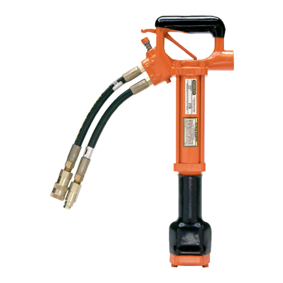
- Page 1 DR19 HYDRAULIC DIGGER USER MANUAL Safety, Operation and Maintenance © 2014 STANLEY Black & Decker, Inc. New Britain, CT 06053 U.S.A. 62213 8/2018 Ver. 8...
-
Page 3: Table Of Contents
REPAIRS AND / OR SERVICE TO THIS TOOL MUST ONLY BE DONE BY AN AUTHORIZED AND CERTIFIED DEALER. For the nearest certified dealer, call STANLEY Infrastructure at (503) 659-5660 and ask for a Customer Service Representative. DR19 User Manual ◄ 3... -
Page 4: Safety Symbols
Enter added precautions in the space provided in this manual. The DR19 Hydraulic Digger will provide safe, dependable service if operated in accordance with the instructions given in this manual. Read and understand the manual any decals, labels, or tags attached to the tool and hoses. - Page 5 • Always replace hoses, couplings, and other parts power source is connected. Accidental engagement with replacement parts recommended by STANLEY. of the equipment can cause serious injury. Refer to the parts list at the end of this manual for part numbers.
-
Page 6: Tool Stickers & Tags
OPERATION MANUAL. OPERATION MANUAL. TAG TO BE REMOVED ONLY BY TAG TO BE REMOVED ONLY BY TOOL OPERATOR. TOOL OPERATOR. SEE OTHER SIDE SEE OTHER SIDE SAFETY TAG P/N 15875 (Shown smaller then actual size) 6 ► DR19 User Manual... -
Page 7: Hose Types
This hose is not certifi ed non-conductive and must never be used near electrical conductors. HOSE SAFETY TAGS To help ensure your safety, the following DANGER tags are attached to all hose purchased from STANLEY. DO NOT REMOVE THESE TAGS. -
Page 8: Hose Recommendations
HOSE RECOMMENDATIONS 8 ► DR19 User Manual... -
Page 9: Htma / Ehtma Requirements
2000 psi 2000 psi (At the power supply outlet) (172 bar) (138 bar) (138 bar) (138 bar) (138 bar) Note: These are general hydraulic system requirements. See tool specifi cation page for tool specifi c requirements. DR19 User Manual ◄ 9... -
Page 10: Operation
3. Observe flow indicators stamped on hose couplers to be sure that oil will flow in the proper direction. The female coupler is the inlet coupler. 10 ► DR19 User Manual... -
Page 11: Tool Protection & Care
Always replace hoses, couplings and other parts • Do not use the tool for applications for which it was with replacement parts recommended by STANLEY. not intended. Supply hoses must have a minimum working pressure rating of 2500 psi/172 bar. -
Page 12: Troubleshooting
Incorrect tool bit. Ensure tool bit meets specifications. Tool operates slow. Low oil flow from power unit. Check power source for proper flow. High back-pressure. Check hydraulic system for excessive back-pressure and correct as required. 12 ► DR19 User Manual... -
Page 13: Specifications
Pressure Range......................1500–2000 psi/105–140 bar Flow Range ..........................7–9 GPM/26–34 LPM Optimum Flow ............................ 8 GPM/30 LPM Porting ..........................3/8" male pipe hose end Length..............................20 inches/51 cm System Type ............................Open Center Accessory Shank ..........................7/8" hex × 3-1/4” DR19 User Manual ◄ 13... -
Page 14: Dr19 Parts Illustration
DR19 PARTS ILLUSTRATION 14 ► DR19 User Manual... -
Page 15: Dr19 Parts List
ROD SEAL 1-1/4 × 1-1/2 × 5/16 × 3/16 04175 INSERT 03127 WIPER RING 03537 RETAINING NOSE ASSEMBLY 03536 RETAINER 03190 SPRING 02436 BALL 03552 RETAINER CAP 03553 CAPSCREW 3/8 × 24 × 2-1/2 02843 DR19 User Manual ◄ 15... - Page 16 STANLEY Infrastructure 6430 SE Lake Road Portland, Oregon 97222 USA (503) 659-5660 / Fax (503) 652-1780 www.stanleyinfrastructure.com...