
Related Manuals for Continental Motors O-200-D


Summary of Contents for Continental Motors O-200-D
- Page 1 O-200-D CONTINENTAL AIRCRAFT ENGINE INSTALLATION OPERATION MANUAL FAA APPROVED Publication OI-2 © 2017 CONTINENTAL MOTORS, INC. JAN 2017...
- Page 2 Available exclusively from the publisher: P.O. Box 90, Mobile, AL 36601 Copyright © 2011, 2015, 2017 Continental Motors, Inc. All rights reserved. This material may not be reprinted, republished, broadcast, or otherwise altered without the publisher's written permission. This manual is provided without express, statutory, or implied warranties. The publisher will not be held liable for any damages caused by or alleged to be caused by use, misuse, abuse, or misinterpretation of the contents.
-
Page 3: January
PREFACE Continental Motors (CM) provides the OI-2 Installation and Operation Manual to owners of CMI engines in accordance with Title 14, Code of Federal Regulations (CFR) Part 33 §33.5. While this manual is provided to owners, it is intended for use only by an OEM or STC aircraft customer for assistance in defining the installation and operational requirements during the initial OEM FAA (or equivalent) Type Certification Process. - Page 4 Intentionally Left Blank O-200-D & X Series Engine Installation and Operation Manual 3 January 2017...
-
Page 5: Table Of Contents
2-2.10.1.Oil Temperature and Pressure Connection Locations ........2-6 2-2.10.2.Oil Flow and Heat Rejection ................2-7 2-2.10.3.Oil Level Gauge....................2-7 2-2.10.4.Oil Filter ......................2-7 2-2.10.5.Oil Cooler Adapter (Optional)................2-7 2-2.11. Electrical System......................2-2.11.1.Starter......................... 2-7 O-200-D & X Series Engine Installation and Operation Manual 3 January 2017... - Page 6 3-1.2. Engine Receipt and Handling ..................3-1.2.1. Uncrating the Engine..................3-2 3-1.2.2. Crating an Engine for Shipping................. 3-2 3-1.2.3. Acceptance Inspection..................3-3 3-1.3. Engine Transport......................3-2. Installation Procedures..................O-200-D & X Series Engine Installation and Operation Manual 3 January 2017...
- Page 7 4-16 4-4.5. High Oil Temperature ....................4-17 4-4.6. Low Oil Pressure......................4-17 4-4.7. In-Flight Restart ......................4-17 4-4.8. Engine Fire In Flight ....................4-18 4-4.9. Propeller Strike......................4-18 O-200-D & X Series Engine Installation and Operation Manual 3 January 2017...
- Page 8 Stud Replacement .................... C-7. Cotter Pin Installation ..................C-8. Fuel System Service ..................C-9. Gasket Maker® Application................C-10. Gasket Installation ................... C-11. Hose and Tubing Installation................C-12. Harness Routing....................O-200-D & X Series Engine Installation and Operation Manual 3 January 2017...
- Page 9 Table 2-3. O-200-D Specifications ................2-23 Table 2-4. O-200-X Specifications ................2-25 Table 2-5. Accessory Drive Ratios ................2-27 Table 2-6. O-200-D & X Accessory Weights .............. 2-32 Table 4-1. Overspeed Categories ................. 4-16 O-200-D & X Series Engine Installation and Operation Manual...
- Page 10 Ignition Distribution - Continental Magnetos ........3-15 Figure 3-9. Ignition Switch Connections to Magneto ........... 3-16 Figure 3-10. O-200-D Engine Installation Drawing - Front and Top View ..... 3-19 Figure 3-11. O-200-D Engine Installation Drawing - Detail Views ......3-21 Figure 3-12.
-
Page 11: Chapter 1. Introduction
Regulations § 33.5, “Instruction manual for installing and operating the engine.” For continued airworthiness instructions, refer to the Instructions for Continued Airworthiness in publication M-2, O-200-D & X Series Engine Maintenance and Overhaul Manual. This manual contains engine interface requirements, installation instructions, installation drawings and operating instructions for O-200-D &... -
Page 12: 1-1.3. Using This Manual
Refer to the AFM/POH published by the aircraft manufacturer for operating instructions and specifications relative to your aircraft. Prior to commencing engine installation, consult the Continental Motors web site to verify the current status of the manual relating to the intended procedure. -
Page 13: Figure 1-1. Figure And Index Reference
Introduction Figure 1-1. Figure and Index Reference O-200-D & X Series Engine Installation and Operation Manual 3 January 2017... -
Page 14: Publications
Some service documents may affect or supplement information in this manual and should be reviewed prior to performing maintenance. All active service documents applicable to the O-200-D & X Series Engine have been incorporated in these instructions as of the date of publication. -
Page 15: Figure 1-2. Change Page Identification
This Manual” on Page A. The list of effective pages, itemizes the pages in each section, by change number. Original pages are designated by a 0 in the List of Effective Pages “Change” column. Figure 1-2. Change Page Identification O-200-D & X Series Engine Installation and Operation Manual 3 January 2017... -
Page 16: Figure 1-3. List Of Effective Pages
Introduction Figure 1-3. List of Effective Pages O-200-D & X Series Engine Installation and Operation Manual 3 January 2017... -
Page 17: 1-2.4. Service Documents
Introduction 1-2.4. Service Documents Continental Motors may issue Service Documents in one of six categories ranging from mandatory (Category 1) to informational (Category 6). Definitions of the categories are listed below: NOTE: Upon FAA approval, Continental Motors publishes service documents for immediate availability on our web site. The service document cover page indicates the engine models affected by the service document. -
Page 18: 1-2.4.1. Service Documents Incorporated In This Manual
Applicable technical information in the service documents listed below, relevant to the engine models covered by this engine manual, have been incorporated in this manual. The full content of active Continental Motors service documents is available at http:// www.continentalmotors.aero. Refer to Section 1-3, “Contact Information” for Continental Motors web site details. -
Page 19: 1-2.4.2. Service Documents Released After Publication
Introduction 1-2.4.2. Service Documents Released After Publication Continental Motors strives to provide clear, concise, and accurate information and instructions based on best known engineering data at the time of publication. Ongoing process improvements may change a specification or procedure after a manual is released. - Page 20 Bulletin Number: Release Date: Affected Sections: Title: Bulletin Number: Release Date: Affected Sections: Title: Bulletin Number: Release Date: Affected Sections: Title: Bulletin Number: Release Date: Affected Sections: 1-10 O-200-D & X Series Engine Installation and Operation Manual 3 January 2017...
-
Page 21: 1-2.5. Related Publications
Introduction 1-2.5. Related Publications The table below lists related publications, source, and accessibility relevant to O-200-D & X Series Engine installation, operation, maintenance & overhaul. WARNING Use only the latest revision of all publications. Using superseded information may jeopardize engine airworthiness. -
Page 22: Contact Information
Introduction 1-3. Contact Information Continental Motors is available to answer technical questions and encourages suggestions regarding products, parts, or service. If customers have an inquiry or require technical assistance, they should contact their local Continental Motors distributor or field representative. To contact a factory representative, refer to the contact information below: Continental Motors, Inc.... -
Page 23: Chapter 2. Engine Description
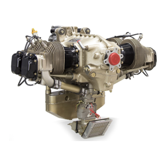
2-1. General Engine Description O-200-D and X model engines are four-cylinder, four-stroke reciprocating aircraft engines, designed for fixed pitch, ground adjustable, or electric constant speed propellers. Cylinder displacement of 200 cubic inches is achieved with a 4.06 inch bore and a 3.88 inch stroke. -
Page 24: 2-1.1. Engine Model Number Definition
The right side cylinders have odd number sequential designation 1-3, with Cylinder 1 • being closest to the rear. Firing order of the engine is 1-3-2-4. • Figure 2-3. Cylinder Number Designation O-200-D & X Series Engine Installation and Operation Manual 3 January 2017... -
Page 25: Aircraft Interface Requirements
Engineering Standard Procedure 7107, Installation Audit. The purpose of the audit is to review compliance with the minimum requirements set forth within this document. Satisfactory completion of the audit is required before Continental Motors will deliver engines in normal production. Continental Motors accepts no responsibility for the airworthiness of any installation of this engine or associated equipment in any aircraft. -
Page 26: 2-2.1. Crankcase Breather Ventilation
The alternate air system design should minimize any accumulation of dust or debris and provide a tight seal when not open to avoid engine contamination during normal operation. O-200-D & X Series Engine Installation and Operation Manual 3 January 2017... -
Page 27: Table 2-1. Recommended Instrument Range Markings
Direct airflow through the engine nacelle to minimize temperatures of fuel system • components Provide auxiliary aircraft operated fuel pumps when necessary • Avoid low points where contaminants or water may collect • O-200-D & X Series Engine Installation and Operation Manual 3 January 2017... -
Page 28: Fuel Supply Hose Routing
The oil pressure monitoring port is located on the lower aft portion of the 1-3 side of the engine crankcase. Oil temperature port: 0.625-18 UNF-3B • Oil pressure port: 0.125-27 NPTF • O-200-D & X Series Engine Installation and Operation Manual 3 January 2017... -
Page 29: Table 2-2. Oil Gauge Rod Error
2-2.6.5. Oil Cooler Adapter (Optional) The O-200-D & X series engines are not supplied with an oil cooler. If an oil cooler is required, an optional oil cooler adapter is available which is attached by three case studs over the pad behind the #2 cylinder. -
Page 30: 2-2.11.4.Spark Plugs
2-2.7.3. Magnetos The O-200-D & X ignition system may be a pair of Champion (formerly Slick) 4300 series magnetos or a CM S4LSC-21 magneto mounted on the left (2-4) side of the engine and one S4LSC-204T magneto mounted on the right (1-3) side of the engine, other combinations are available (See Section 2-4.6). -
Page 31: 2-2.13. Engine Mount Isolators
Maximum Load (Gs) Positive Load plus Engine Torque Negative Load Side Load 2-2.11. Propeller System O-200-D & X series do not provide hydraulic control for propeller pitch control. A fixed pitch propeller is recommended. 2-2.11.1. Propeller Drive Type - Flanged, Six-hole CM/Cessna Bolt Circle Diameter 4.0”... -
Page 32: Detailed Engine Description
BEARING BORE BEARING BORE CAMSHAFT CAMSHAFT SPINE BELOW SPINE BELOW BEARING BORE BEARING BORE OIL SUMP OIL SUMP CAMSHAFT CAMSHAFT MOUNT FLANGE MOUNT FLANGE Figure 2-4. Crankcase Features 2-10 O-200-D & X Series Engine Installation and Operation Manual 3 January 2017... -
Page 33: 2-3.2. Engine Drive Train
Driven Gear Camshaft Gear Camshaft Gear Camshaft Gear Oil Pump Drive Gear Oil Pump Drive Gear Oil Pump Drive Gear Alternator Alternator Alternator Figure 2-5. Engine Drive Train O-200-D & X Series Engine Installation and Operation Manual 2-11 3 January 2017... -
Page 34: 2-3.2.1. Crankshaft
The portion of the rod between the rod and the crankpin and piston pin ends is called the “I” beam. A split steel-backed bronze bushing is pressed into the piston pin end and 2-12 O-200-D & X Series Engine Installation and Operation Manual 3 January 2017... -
Page 35: 2-3.2.3. Camshaft
The camshaft is hollow to reduce total engine weight. FRONT REAR #3 & 4 #1 & 2 #4 EXH #3 EXH #2 EXH #1 EXH INTAKE INTAKE M/J - MAIN JOURNAL Figure 2-8. Camshaft O-200-D & X Series Engine Installation and Operation Manual 2-13 3 January 2017... -
Page 36: 2-3.3. Accessory Case
(two per cylinder). As the mixture is 2-14 O-200-D & X Series Engine Installation and Operation Manual 3 January 2017... -
Page 37: Figure 2-10. Cylinder Features
SEAT VALVE GUIDE VALVE GUIDE VALVE SEAT VALVE SEAT INSERT INSERT COOLING FINS COOLING FINS EXHAUST VALVE EXHAUST VALVE INTAKE VALVE INTAKE VALVE Figure 2-10. Cylinder Features O-200-D & X Series Engine Installation and Operation Manual 2-15 3 January 2017... -
Page 38: 2-3.4.1. Pistons
The interface between a cam lobe and tappet is intended to wear to some degree as the engine operates. This is similar to the piston ring / cylinder wall interface that must seat together for proper operation and wear over time. 2-16 O-200-D & X Series Engine Installation and Operation Manual 3 January 2017... -
Page 39: 2-3.5. Lubrication System
The oil pump driven gear is supported by a shaft pressed into the accessory case and the oil pump cover plate. The oil pump drive gear shaft is supported by bushings pressed into the accessory case. O-200-D & X Series Engine Installation and Operation Manual 2-17 3 January 2017... -
Page 40: 2-3.5.2. Oil Sump
Its passages are connected to the oil pump outlet passage. This valve opens when the oil pump pressure exceeds the specified operating limit and directs oil back to the oil sump. 2-18 O-200-D & X Series Engine Installation and Operation Manual 3 January 2017... -
Page 41: 2-3.5.4. Oil Cooler Adapter
Two magnetos, installed on the aft side of the accessory case use magneto drive adapters to interface with the crankshaft gear. O-200-D & X series engines are fitted with either Champion (formerly Slick) or Continental Motors (Bendix) magnetos, designed to provide ignition for four cylinder aircraft engines. -
Page 42: Figure 2-15. Continental Motors Magneto Part Number Structure
3200: With Retard Breaker SC = Short Cover SC = Short Cover Figure 2-15. Continental Motors Magneto Part Number Structure Figure 2-16. Champion Ignition Harness Routing (typical) 2-20 O-200-D & X Series Engine Installation and Operation Manual 3 January 2017... -
Page 43: 2-3.7. Starter Assembly
For a description of the aircraft electrical and charging system, see the applicable aircraft Instructions for Continued Airworthiness. For a detailed description of Continental Motors alternators, refer to Continental Motors Alternator Service Instructions. -
Page 44: 2-3.10. Fuel System
The front end of the air intake flares upward to match the outline of the air filter. A hot air supply tube and a fuel drain tube are incorporated in the air intake housing. 2-22 O-200-D & X Series Engine Installation and Operation Manual 3 January 2017... -
Page 45: Engine Specifications
Exhaust System back pressure, maximum, measured 1.5 inches from port flange, in Hg 2.0 (6.75) (kPa) EGT Thermocouple Probe, minimum distance from port, in. (mm) 2.0/2.50 (50.8/63.5) O-200-D & X Series Engine Installation and Operation Manual 2-23 3 January 2017... - Page 46 Standard day conditions are 29.92 in. Hg and 59°F. Horsepower will vary approximately 1% for each 10°F (5.6° C) change in inlet air temperature. Correction must also be made for the effect of exhaust back pressure and accessory drive losses. Contact Continental Motors engineering for correction factors for specific applications.
-
Page 47: Table 2-4. O-200-X Specifications
Exhaust System back pressure, maximum, measured 1.5 inches from port flange, in Hg 2.0 (6.75) (kPa) EGT Thermocouple Probe, minimum distance from port, in. (mm) 2.0/2.50 (50.8/63.5) O-200-D & X Series Engine Installation and Operation Manual 2-25 3 January 2017... - Page 48 Standard day conditions are 29.92 in. Hg and 59°F. Horsepower will vary approximately 1% for each 10°F (5.6° C) change in inlet air temperature. Correction must also be made for the effect of exhaust back pressure and accessory drive losses. Contact Continental Motors engineering for correction factors for specific applications.
-
Page 49: 2-4.1. Accessory Drive Ratios
Alternator (gear driven) 2.035:1 1. CW=Clockwise Rotation CCW=Counterclockwise rotation; viewed facing the drive; OPT= Optional 2-4.2. Induction Induction system specifications apply to all O-200-D & X engine model specifications. Mass Flow Sea level, standard day conditions, 100 bhp 700 lbs./hr. -
Page 50: 2-4.5. Performance Data
2-4.5. Performance Data The O-200-X model engine is a copy of the base configuration of the O-200-D4B minus all accessories. The same accessories available for the O-200-D are available on the O- 200-X configuration as cafeteria type selections. Performance specifications for both engine models are identical. -
Page 51: 2-4.5.1. O-200-D & X Performance Charts
1 gph = 5.87 lbs/hr Data Measured at Sea Level, Standard Dry Day Conditions, Minimum Engine Corrected Brake Horse Power Figure 2-18. Fuel Flow vs. Brake Horsepower O-200-D & X Series Engine Installation and Operation Manual 2-29 3 January 2017... -
Page 52: Figure 2-19. Full Throttle And Prop Load Curves
Full Rich Fuel Mixture, Minimum Engine. 0.45 1900 2000 2100 2200 2300 2400 2500 2600 2700 2800 Engine Speed (rpm) Figure 2-19. Full Throttle and Prop Load Curves 2-30 O-200-D & X Series Engine Installation and Operation Manual 3 January 2017... -
Page 53: Figure 2-20. Sea Level Performance
2000 3000 4000 5000 6000 7000 8000 9000 10000 11000 12000 13000 14000 15000 16000 17000 18000 Altitude from Sea Level (ft) Figure 2-21. Altitude Performance (uninstalled) O-200-D & X Series Engine Installation and Operation Manual 2-31 3 January 2017... -
Page 54: 2-4.6. Accessory Weights
1.78 Oil Sump Filler Neck on 2-4 side Filler Neck on 1-3 side Oil Cooler Adapter 0.63 Total Weight by Specification 196.78 188.20 196.78 188.20 188.20 2-32 O-200-D & X Series Engine Installation and Operation Manual 3 January 2017... -
Page 55: Chapter 3.Engine Installation
13. Spark Plug Manufacturer’s recommended spark plug thread lubricant 14. Part No. 646943 Anti-seize lubricant 15. Loctite 592 Pipe Sealant 16. Other supplies required by the aircraft manufacturer’s instructions O-200-D & X Series Engine Installation and Operation Manual 3 January 2017... -
Page 56: 3-1.2. Engine Receipt And Handling
1. Lower the engine onto the container base. 2. Attach the engine using shock mounts and bolts. 3. Cover the engine with a plastic bag. 4. Install and attach the container cover to the base. O-200-D & X Series Engine Installation and Operation Manual 3 January 2017... -
Page 57: 3-1.2.3. Acceptance Inspection
2. Take up slack on the hoist prior to loosening the engine mount bolts; remove the bolts from the shipping shock mounts. 3. Lift the engine and install it on a transportation stand or dolly. O-200-D & X Series Engine Installation and Operation Manual 3 January 2017... -
Page 58: Installation Procedures
3. Place a basin under the engine to catch the cylinder preservation oil. NOTE: A small amount of preservative oil remaining in the cylinder bore is acceptable; it will burn off during the first engine start. O-200-D & X Series Engine Installation and Operation Manual 3 January 2017... -
Page 59: 3-2.3. Installation Sequence
2. Connect the aircraft fuel supply to the carburetor according to aircraft manufacturer’s instructions. 3. Connect the starter and alternator wiring according to the aircraft manufacturer’s instructions. O-200-D & X Series Engine Installation and Operation Manual 3 January 2017... - Page 60 14. Perform an “Installation Inspection” according to instructions in Section 3-2.4. 15. Perform the “Engine Operational Check” according to instructions in Section 6-3.6 of M-2, Maintenance and Overhaul Manual. O-200-D & X Series Engine Installation and Operation Manual 3 January 2017...
-
Page 61: 3-2.3.1. Engine Pre-Oiling
12. Turn the aircraft fuel selector valve to the OFF position. 13. Correct any discrepancies noted. 14. Dispose of the fuel/oil mixture in accordance with Federal and State Hazardous Material Regulations. O-200-D & X Series Engine Installation and Operation Manual 3 January 2017... -
Page 62: 3-2.4. Installation Inspection
Verify the harness outlet plate is securely fastened to the magneto. c. Check the security of ignition harness, including the spark plug leads. Inspect ignition leads for proper routing and connection security. O-200-D & X Series Engine Installation and Operation Manual 3 January 2017... - Page 63 25-hour break-in. After installation, avoid prolonged ground operation at high power. 1Procedure 1. Perform an “Engine Operational Check” instructions in Section 6-3.6 of the Maintenance and Overhaul Manual (M-2). O-200-D & X Series Engine Installation and Operation Manual 3 January 2017...
- Page 64 Section 2-4. 3. Correct discrepancies according to instructions in M-2, Maintenance and Overhaul Manual. 4. Perform a “Flight Check and Break-In” according to instructions in Section 4-2.3. 3-10 O-200-D & X Series Engine Installation and Operation Manual 3 January 2017...
-
Page 65: Engine Installation Drawings
Pay particular attention to the engine models depicted when referencing drawings for engine installation requirements. 3-3.1. O-200-D & X Series Engine Common Installation Drawings Figure 3-1. Propeller Flange Figure 3-2. Exhaust Flange Dimensions O-200-D &... -
Page 66: Figure 3-3. 60 Amp Alternator Detail
Engine Installation Figure 3-3. 60 Amp Alternator Detail Figure 3-4. 50 Amp Alternator Detail 3-12 O-200-D & X Series Engine Installation and Operation Manual 3 January 2017... -
Page 67: Figure 3-5. Engine Mounts
Engine Installation Figure 3-5. Engine Mounts O-200-D & X Series Engine Installation and Operation Manual 3-13 3 January 2017... -
Page 68: Figure 3-6. Starter Connection Details
Engine Installation Figure 3-6. Starter Connection Details 3-14 O-200-D & X Series Engine Installation and Operation Manual 3 January 2017... -
Page 69: Figure 3-7. Ignition Distribution - Champion (Slick) Magnetos
Engine Installation Figure 3-7. Ignition Distribution - Champion (Slick) Magnetos Figure 3-8. Ignition Distribution - Continental Magnetos O-200-D & X Series Engine Installation and Operation Manual 3-15 3 January 2017... -
Page 70: Figure 3-9. Ignition Switch Connections To Magneto
Engine Installation Figure 3-9. Ignition Switch Connections to Magneto 3-16 O-200-D & X Series Engine Installation and Operation Manual 3 January 2017... -
Page 71: 3-3.2. O-200-D Installation Drawings
3-3.2. O-200-D Installation Drawings Figure 3-9. O-200-D Engine Installation Drawing - Left Side and Rear Views O-200-D & X Series Engine Installation and Operation Manual 3-17(Reverse Blank) 3 January 2017... - Page 72 Intentionally Left Blank 3-18 O-200-D & X Series Engine Installation and Operation Manual 3 January 2017...
-
Page 73: Figure 3-10. O-200-D Engine Installation Drawing - Front And Top View
Figure 3-10. O-200-D Engine Installation Drawing - Front and Top View O-200-D & X Series Engine Installation and Operation Manual 3-19(Reverse Blank) 3 January 2017... - Page 74 Intentionally Left Blank 3-20 O-200-D & X Series Engine Installation and Operation Manual 3 January 2017...
-
Page 75: Figure 3-11. O-200-D Engine Installation Drawing - Detail Views
Figure 3-11. O-200-D Engine Installation Drawing - Detail Views O-200-D & X Series Engine Installation and Operation Manual 3-21(Reverse Blank) 3 January 2017... - Page 76 Intentionally Left Blank 3-22 O-200-D & X Series Engine Installation and Operation Manual 3 January 2017...
-
Page 77: Figure 3-12. O-200-X Engine Installation Drawing - Left Side And Rear Views
3-3.3. O-200-X Installation Drawings Figure 3-12. O-200-X Engine Installation Drawing - Left Side and Rear Views O-200-D & X Series Engine Installation and Operation Manual 3-23(Reverse Blank) 3 January 2017... - Page 78 Intentionally Left Blank 3-24 O-200-D & X Series Engine Installation and Operation Manual 3 January 2017...
-
Page 79: Figure 3-13. O-200-X Engine Installation Drawing - Top And Front Views
Figure 3-13. O-200-X Engine Installation Drawing - Top and Front Views O-200-D & X Series Engine Installation and Operation Manual 3-25(Reverse Blank) 3 January 2017... - Page 80 Intentionally Left Blank 3-26 O-200-D & X Series Engine Installation and Operation Manual 3 January 2017...
-
Page 81: Figure 3-14. O-200-X Engine Installation Drawing - Detail Views
Figure 3-14. O-200-X Engine Installation Drawing - Detail Views O-200-D & X Series Engine Installation and Operation Manual 3-27(Reverse Blank) 3 January 2017... - Page 82 Intentionally Left Blank 3-28 O-200-D & X Series Engine Installation and Operation Manual 3 January 2017...
-
Page 83: Chapter 4. Engine Operation
Section 4-4 and Section 4-5 prior to the occurrence of such conditions. Whenever abnormal conditions arise, timely response is critical. This chapter contains the O-200-D and X Series engine operating instructions to supplement the AFM/POH. Flight Prerequisites •... -
Page 84: 4-2.1. Oil Change Interval
MIL-DTL-85470B, if approved by the aircraft manufacturer, may be added for this purpose. Refer to Chapter 3 of the Standard Practice Maintenance Manual (M-0). O-200-D & X Series Engine Installation and Operation Manual 3 January 2017... -
Page 85: 4-2.3. Flight Check And Break-In
Engine Operation 4-2.3. Flight Check and Break-In New and factory rebuilt Continental Motors engines are adjusted to un-installed factory specifications in a test cell prior to shipment. A flight check ensures the engine meets operational and performance specifications after installation in the aircraft, prior to release for normal service. -
Page 86: 4-2.3.2. Flight Check
4. If the aircraft indicated values fail to meet the published limits, repeat the Engine Operational Check and Flight Check. WARNING All abnormal conditions must be corrected prior to releasing the aircraft for normal operation. 4. Release the engine to normal service. O-200-D & X Series Engine Installation and Operation Manual 3 January 2017... -
Page 87: Normal Operation
Climbing/Ascent • Cruising • Descent • Landing/Approach • Engine Shutdown • 4-3.1. Pre-operational Requirements Refer to the Pre-operational Requirements in Section 7-3.1 of M-0, Standard Practice Maintenance Manual. O-200-D & X Series Engine Installation and Operation Manual 3 January 2017... -
Page 88: 4-3.2. Engine Start
If the engine is hot, do not prime before starting. After priming, turn the primer handle to the “LOCKED” position to prevent the engine from drawing fuel from the primer. O-200-D & X Series Engine Installation and Operation Manual 3 January 2017... -
Page 89: 4-3.2.1. Cold Start
3. Ignition Switch..........START (momentarily) Engage the starter for short durations multiple times to clear the combustion chamber of excess fuel. 4. Repeat normal start procedure without additional priming. O-200-D & X Series Engine Installation and Operation Manual 3 January 2017... -
Page 90: 4-3.3. Ground Run-Up
RESULT: Noticeable RPM (not to exceed 150 RPM) drop and slight engine roughness; record Left Magneto channel drop results. Maximum allowable RPM drop spread between magneto channels is 75 RPM. O-200-D & X Series Engine Installation and Operation Manual 3 January 2017... - Page 91 1) Ignition Switch ........BOTH 2) Throttle..........2200 RPM 3) Mixture Control........lean until RPM peaks for 10 seconds. 4) Mixture Control........FULL RICH 7. Throttle............. 1200 RPM O-200-D & X Series Engine Installation and Operation Manual 3 January 2017...
-
Page 92: 4-3.4. Taxi Preparation
Refer to troubleshooting procedures in Chapter 8 of the Maintenance and Overhaul Manual (M-2). 4. Monitor Engine Gauges not to exceed operating limits a. Tachometer b. Fuel Flow (if equipped) 4-10 O-200-D & X Series Engine Installation and Operation Manual 3 January 2017... -
Page 93: Cruise Climb
Advance the mixture control slowly toward the “FULL RICH” position until slight RPM reduction is observed on tachometer. This setting is referred to as “Best Power Cruise.” O-200-D & X Series Engine Installation and Operation Manual 4-11 3 January 2017... -
Page 94: Descent
For landing and approach procedures, refer to the AFM/POH. In anticipation of a go around and subsequent need for higher power, set the Mixture Control to FULL RICH. 4-12 O-200-D & X Series Engine Installation and Operation Manual 3 January 2017... -
Page 95: Engine Shutdown
Maximum allowable RPM drop spread between channels is 75 RPM. 5. Ignition Switch..........BOTH 6. Throttle............. IDLE 7. Mixture Control ..........IDLE CUT-OFF Wait for the propeller to stop... O-200-D & X Series Engine Installation and Operation Manual 4-13 3 January 2017... -
Page 96: Emergency Operation
Land at the nearest airport suitable for the aircraft. Land at the best available landing area within aircraft Land as Soon as Possible: gliding distance, following instructions in the AFM/POH 4-14 O-200-D & X Series Engine Installation and Operation Manual 3 January 2017... -
Page 97: 4-4.1. Engine Fire During Start
“Engine Operational Check” according to instructions in Section 6-3.6 of M-2, Maintenance and Overhaul Manual to evaluate engine performance versus specifications. O-200-D & X Series Engine Installation and Operation Manual 4-15 3 January 2017... -
Page 98: 4-4.3. Engine Overspeed
3. Airspeed ............Increase If temperature cannot be maintained within limits, reduce power, LAND AS SOON AS PRACTICAL and have the malfunction evaluated prior to further flight. 4-16 O-200-D & X Series Engine Installation and Operation Manual 3 January 2017... -
Page 99: 4-4.5. High Oil Temperature
If the oil pressure drops suddenly from a normal indication of 30-60 psi, monitor temperature closely and LAND AS SOON AS POSSIBLE. Have the engine inspected prior to further flight. O-200-D & X Series Engine Installation and Operation Manual 4-17 3 January 2017... -
Page 100: 4-4.7. In-Flight Restart
Propeller strikes can cause engine and component damage even if the propeller continues to rotate. Perform a “Propeller Strike Inspection” according to the instructions in Section 6-5.1.1 of M-0, Standard Practice Maintenance Manual after any propeller strike event. 4-18 O-200-D & X Series Engine Installation and Operation Manual 3 January 2017... -
Page 101: Engine Operation In Abnormal Environments
7-4.1.1.2 of M-0, Standard Practice Maintenance Manual. 4-5.1.1.3. Cold Weather Starting Without Preheating Refer to the “Cold Weather Starting without Preheating” instructions in Section 7-4.1.1.3 of M-0, Standard Practice Maintenance Manual. O-200-D & X Series Engine Installation and Operation Manual 4-19 3 January 2017... -
Page 102: Engine Operation In Hot Weather
Inspect the induction air filter frequently for contamination; be prepared to clean or • replace it, if necessary. If the aircraft is flown in dusty conditions, Continental Motors recommends more • frequent oil changes. Use dust covers over openings in the cowling for additional protection. -
Page 103: Ground Operation In Hot Weather
3. Monitor temperatures closely. 4. Maintain sufficient airspeed and attitude to provide engine cooling. 5. Cowl flaps ............FULLY OPEN (if equipped) O-200-D & X Series Engine Installation and Operation Manual 4-21 3 January 2017... -
Page 104: Ground Operation At High Density Altitude
If take-off is not to be made immediately following engine run-up, face the aircraft into • the wind with the engine idling between 900-1000 RPM. 4-6. Troubleshooting Engine troubleshooting instructions are in Chapter 8 of the Maintenance and Overhaul Manual. 4-22 O-200-D & X Series Engine Installation and Operation Manual 3 January 2017... - Page 105 Glossary Appendix A. Glossary Refer to Appendix A in M-0, Standard Practice Maintenance Manual. O-200-D & X Series Engine Installation and Operation Manual 3 January 2017...
- Page 106 Glossary Intentionally Left Blank O-200-D & X Series Engine Installation and Operation Manual 3 January 2017...
- Page 107 Torque Specifications Appendix B.Torque Specifications Refer to Appendix B in M-0, Standard Practice Maintenance Manual. O-200-D & X Series Engine Installation and Operation Manual 3 January 2017...
- Page 108 Torque Specifications Intentionally Left Blank O-200-D & X Series Engine Installation and Operation Manual 3 January 2017...
-
Page 109: C-1. Handling Parts
C-7. Cotter Pin Installation Refer to Appendix C-7 in M-0, Standard Practice Maintenance Manual. C-8. Fuel System Service Refer to Appendix C-8 in M-0, Standard Practice Maintenance Manual. O-200-D & X Series Engine Installation and Operation Manual 3 January 2017... -
Page 110: C-10. Gasket Installation
C-11. Hose and Tubing Installation Refer to Appendix C-11 in M-0, Standard Practice Maintenance Manual. C-12. Harness Routing Refer to Appendix C-12 in M-0, Standard Practice Maintenance Manual. O-200-D & X Series Engine Installation and Operation Manual 3 January 2017... - Page 112 www.continentalmotors.aero...
Need help?
Do you have a question about the O-200-D and is the answer not in the manual?
Questions and answers