Advertisement
SERVICE
MANUAL
CONTENTS
SPECIFICATIONS ........................................................................................................................... 2
OUTLINE AND DIMESIONS ............................................................................................................ 3
FUNCTIONS ...................................................................................................................................... 5
OPERATION DETAILS ......................................................................................................................... 6
SELF-DIAGNOSIS OPERATION ....................................................................................................... 10
MALFUNCTION ................................................................................................................................. 11
DIP SWITCH FUNCTION .................................................................................................................... 12
CIRCUIT DIAGRAM ........................................................................................................................... 13
SENSOR RESISTANCE VALUE SHEET ................................................................................................ 15
EXPLODED VIEW ............................................................................................................................ 17
PARTS LIST ....................................................................................................................................... 20
DC INVERTER
AIR CONDITIONER
WINDOW
Models
IWAR-2910
IWAR-3615
IWAR-5020
- 1 -
type
Advertisement
Table of Contents

Related Manuals for FUJIDENZO IWAR-2910


Summary of Contents for FUJIDENZO IWAR-2910
-
Page 1: Table Of Contents
DC INVERTER AIR CONDITIONER WINDOW type SERVICE Models IWAR-2910 MANUAL IWAR-3615 IWAR-5020 CONTENTS SPECIFICATIONS …………………………………………………………………………………………………………… 2 OUTLINE AND DIMESIONS ……………………………………………………………………………………………... 3 FUNCTIONS …………………………………………………………………………………………………………………….. 5 OPERATION DETAILS …………………………………………………………………………………………………………. 6 SELF-DIAGNOSIS OPERATION …………………………………………………………………………………………. 10 MALFUNCTION ………………………………………………………………………………………………………………… 11 DIP SWITCH FUNCTION …………………………………………………………………………………………………….. 12 CIRCUIT DIAGRAM ……………………………………………………………………………………………………………... -
Page 2: Specifications
SPECIFICATIONS MODEL NO. IWAR-2910 IWAR-3615 IWAR-5020 POWER SUPPLY 230V,1PH,60Hz 9894BTU/Hr 12500BTU/Hr 18000BTU/Hr COOLING CAPACITY 10438kJ/Hr 13188kJ/Hr 18990kJ/Hr 13.4 13.5 13.1 (kJ/W-Hr) STARTING CURRENT RATED RUNNING 5.3A 5.45A 7.55A CURRENT RATED POWER 780W 980W 1.455KW CONSUMPTION REFRIGERANT R410A RECHARGE AMOUNT 0.79kg 1.07kg... -
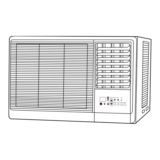
Page 3: Outline And Dimesions
OUTLINE AND DIMENSION Model : IWAR-2910 Machine Dimension : Height 400 X Width 560 X Depth 630mm Installation Dimension : Height 410 X Width 580 mm - 3 -... - Page 4 OUTLINE AND DIMENSION Model : IWAR-3615, IWAR-5020 Machine Dimension : Height 435 X Width 660 X Depth 720mm Installation Dimension : Height 445 X Width680 mm - 4 -...
-
Page 5: Functions
FUNCTIONS Indicator Button Button Setting Button Button 1. 【 Digital Indicator】(RED): - It displays room temperature when power off. - It displays setting temperature for 5 seconds - then return to display indoor temperature. - It displays error code when malfunction 2. -
Page 6: Operation Details
OPERATION DETAILS AUTO Mode Condition of AUTO mode switching: Setting Temperature room temp. pair operation mode temp. 25℃ 25℃≦temp.≦27℃ temp. 27℃ ▲ Standard FAN DRY COOL Auto Operation temp. 23℃ 23℃≦temp.≦25℃ temp. 25℃ Standard FAN DRY COOL Temp. 21℃ 21℃≦temp.≦23℃ temp. 23℃ Standard ▼ FAN DRY COOL COOL Mode 1. The temp. range of setting is between 16℃~32℃. 2. Auto, high, medium and low speeds are available. 3. The condition of compressor stop running: it has to keep in the lowest speed for 3 minute to reduce the ON/OFF frequency of compressor. ... - Page 7 OPERATION DETAILS Room Temp. Compressor operates according to COOL Mode Setting Temp. Compressor operates according to DRY Mode Setting Temp.-1℃ Setting Temp.-2℃ Compressor will stop after operating in the lowest speed for 3 minutes ...
- Page 9 OPERATION DETAILS Setting Memory Function 1. Unit has memory device, the memory contents will be Power ON/OFF, operation mode, FAN speed, FAN direction, setting temp, and the previous status of SLEEP and AIR function. 2. When unit has both power failure memory and AUTO restart functions, unit will remain power OFF status after power restored if it is in power OFF status when power failure and it will remain power ON status after power restored if it is in power ON status when power failure.
-
Page 10: Self-Diagnosis Operation
Self-diagnosis Operation Indication Lamp Reason The Operation indication lamp Light on means the unit operates. flash (GREEN) Flash means the compressor stops in the condition of operation. The TIMER indication lamp flash Flash means is setting TIMER. ... -
Page 11: Malfunction
Indoor Unit PCB Indicator Message Solu on Indica on Check if the co cord Wrong Signal between main control board and Show【E1】 Flash Once driving board Check the voltage and the DC high Error happens on the voltage Show【E2】 tension cord DBL, DBN, DCN1, DCP1 Flash Twice and DCP2 on driving board. -
Page 12: Dip Switch Function
DIP SWITCH FUNCTION Main Controller PCB Board DIP Switch ON OFF Factory Default Switch 1 w/o Auto power on Auto power on ON Switch 2 w/o Time shortness Time shortness (test mode) ON Switch 3 Remote controller with A code Remote controller with B code ON w/o 200 hours filter cleaning 200 hours filter cleaning Switch 4 ON indication indication Switch 5 w/o Power failure memory Power failure memory ON Power button can not be Power button can be operated Switch 6 ON operated when KEY LOCKED when KEY LOCKED * Noted: Power must be shut off when DIP Switch reset. ... -
Page 13: Circuit Diagram
CIRCUIT DIAGRAM Model : IWAR-2910 綠滾黃 Green with Yellow 接地線 Earthing FUSE2 15A/250V 黑 Black AC電源 綠 Green AC Power 黑 Black 白 White 接地線 Earthing 起動電容 Starting Capacitor 操作面板 Operation Panel 紅 黑 Black 風扇 黑 Black 室溫 Room Temperature Sensor 擺葉... - Page 14 CIRCUIT DIAGRAM Model : IWAR-3615, IWAR-5020 綠滾黃 Green with Yellow 接地線 Earthing 黑 Black AC電源 綠 Green AC Power 黑 Black 白 White 接地線 Earthing 起動電容 Starting Capacitor 操作面板 Operation Panel 紅 黑 Black 風扇 黑 Black 室溫 Room Temperature Sensor 擺葉...
-
Page 15: Sensor Resistance Value Sheet
SENSOR RESISTANCE VALUE COMPRESSOR DISCHARGE TUBE SENSOR RESISTANCE VALUE Rmax. Rnor. Rmin. (℃) (KΩ) (KΩ) (KΩ) 59.517 58.796 58.078 56.855 56.192 55.531 54.327 53.717 53.109 51.924 51.365 50.806 49.641 49.128 48.615 47.470 47.000 46.530 45.446 44.976 44.507 43.519 43.050 42.582 41.684 41.217 40.751... - Page 16 SENSOR RESISTANCE VALUE OTHER SENSOR RESISTANCE VALUE =10 KOhm ± 3% ℃ B25/85 = 3977 K ± 1.5% ℃ Temperature Rmax. Rnor. Rmin. Temperature Tol. (℃) (℃) (KΩ) (KΩ) (KΩ) 12.87480356 12.47906428 12.08460309 -0.70395 0.701677835 12.306665 11.93239706 11.55909873 -0.70062 0.698802644 11.76659934 11.41256767 11.05922579...
-
Page 17: Exploded View
EXPLODED VIEW Model : IWAR-2910 - 17 -... - Page 18 EXPLODED VIEW Model : IWAR-3615, IWAR-5020 - 18 -...
- Page 19 PARTS LIST Model : IWAR-2910, IWAR-3615, IWAR-5020 Parts Name IWAR-2910 IWAR-3615 IWAR-5020 Unit Base Assembly 03A000002-00 WA20-0002-00 WA20-0002-00 Pass Partition Plate Set WA29-0002-00 WS16-0006 WS16-0006 Drain Pan Styrofoam 06D000012-00 06D000021-00 06D000021-00 Styrofoam Assembly of Indoor Side Fan Shell 06D000011-00 06D000020-00...
-
Page 20: Parts List
PARTS LIST Model : IWAR-2910, IWAR-3615, IWAR-5020 Parts Name IWAR-2910 IWAR-3615 IWAR-5020 Vertical Louver Assembly 00A100002-00 00A100003-00 00A100003-00 Filter Assembly 00F100032-00 WS08-0001 WS01-0005 Air Intake Panel Assembly WB12-0003-00 WD12-0005 WD12-0005 Touchable Panel Assembly 04F000046-00 04F000048-00 04F000048-00 TiO2 Filter Assembly (optional)
Need help?
Do you have a question about the IWAR-2910 and is the answer not in the manual?
Questions and answers
H3 display but unit s cooling cant control to remote