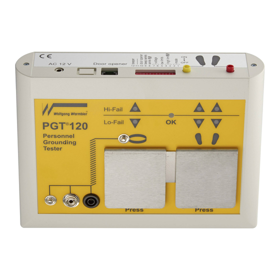
Summary of Contents for Warmbier PGT 120
- Page 1 ® 120.COM Personnel Grounding Tester Wrist Strap and Footwear Tester with serial port User's Manual...
-
Page 2: Table Of Contents
® 120.COM Art.Nr. 7100.PGT120.COM 1 Table of contents INHALTSVERZEICHNIS ................. 2 ALLGEMEINES ....................4 Rücknahme und umweltverträgliche Entsorgung ........4 INBETRIEBNAHME ..................5 BEDIENUNG ....................6 Gelenkbandprüfung einzeln ................6 Spiralkabelprüfung einzeln ................6 Schuhprüfung einzeln ................... 7 Gelenkband- und Schuhprüfung gemeinsam ..........7 Schuhprüfung als Reihenschaltung ............. - Page 3 ® 120.COM Art.Nr. 7100.PGT120.COM Wrist strap and footwear test ............... 7 Footwear in series ..................8 CONFIGURATION ................... 9 DATA OUTPUT VIA RS232 ................10 CONNECTORS ....................12 WALL MOUNTING INSTRUCTIONS .............14 SPECIFICATIONS ..................15 PICTURES ......................16 3 / 17 2016-09-07...
-
Page 4: Allgemeines
® 120.COM Art.Nr. 7100.PGT120.COM 2 Introduction ® The Personnel Grounding Tester PGT 120.COM is an electronic test instrument for checking personnel grounding systems such as wrist straps, coil cords and footwear. ® The PGT 120 is suitable for compliance verification of the above products, according to the IEC 61340-5-1 Edition 1.0 (2007-08) or ANSI/ESD S 20.20 –... -
Page 5: Inbetriebnahme
® 120.COM Art.Nr. 7100.PGT120.COM 3 Installation The Unit is for desktop or wall mounting. The optionally available wall mounting frame (Part No. 7100.PGT120.WK) can be used to fix the unit to a wall. The power is supplied by a power supply. Use only an original power supply connected to the "AC12V"... -
Page 6: Bedienung
® 120.COM Art.Nr. 7100.PGT120.COM 4 Operation This tester has no power switch. Connecting the power supply activates the electrical circuit. The measuring voltage is preset to 100V. Use the DIP switches 6+7 to adjust the voltage to either 30V or 50V. 4.1 Wrist strap test ... -
Page 7: Schuhprüfung Einzeln
® 120.COM Art.Nr. 7100.PGT120.COM 4.3 Footwear test (single shoe) Settings: Only footwear or OR is activated (DIP switch 1+2; RS232) Stand on the foot electrode, then press the right electrode and keep it pressed. A peep signal indicates the start of measurement. After a short measuring time the result is displayed. -
Page 8: Schuhprüfung Als Reihenschaltung
® 120.COM Art.Nr. 7100.PGT120.COM 4.5 Footwear in series Settings: Footwear in series activated (DIP switch 8) To show that "Footwear in series" is activated the red LED's for Hi-Fail of Footwear flash for a short time every 2s, while disspative shoes are not detected. The footwear test can be accomplished hands free, without touching a electrode. -
Page 9: Konfiguration
® 120.COM Art.Nr. 7100.PGT120.COM 5 Configuration The unit can be configured with the DIP switches on the rear according to the table below. Standard settings are marked bold. Switch 1 Switch 2 Test mode "OR" (wrist strap or footwear test) Only footwear test Only wrist strap test "AND"... -
Page 10: Datenausgabe Über Rs232
® 120.COM Art.Nr. 7100.PGT120.COM 6 Data output via RS232 Measured values and test result were output via serial port. No. Sense Start Prefix Data value value in kOhm footwear in <STX> RSG <SP> <ETX> <CR> <LF> (UNR under range) (OVR ... - Page 11 ® 120.COM Art.Nr. 7100.PGT120.COM Error no. Sense Resistance wrist strap to low Resistance wrist strap to high Resistance left shoe to low Resistance left shoe to high Resistance right shoe to low Resistance right shoe to high Voltage to low or to high contact electrode was released to early If several errors occur the error numbers are added.
-
Page 12: Anschlüsse
® 120.COM Art.Nr. 7100.PGT120.COM 7 Connectors The connectors for the power supply, the foot electrode, the door opener and the serial port are located on the rear side of the unit. Use a "RJ12" western modular plug to connect the dry contact of the door opener. The door opener relay is triggered and stays for 1s or 3 seconds when the test result indicates OK. - Page 13 ® 120.COM Art.Nr. 7100.PGT120.COM ® The PGT 120.COM has a serial port RS232 to communicate with a PC or terminal. The connector is located on the rear side of the unit. ® Use a "RJ45" western modular plug to connect PGT 120.COM to PC or terminal.
-
Page 14: Montageanleitung Wandkonsole
® 120.COM Art.Nr. 7100.PGT120.COM 8 Wall mounting instructions (Part No. 7100.PGT120.WK) Fix the wall mounting plate with the supplied dowels and screws and stick the self- adhesive Velcro tapes according to the picture. ® 1. The surface of the plate and the bottom side of the PGT 120.COM have to be clean, dry and free of grease. -
Page 15: Technische Daten
® 120.COM Art.Nr. 7100.PGT120.COM 9 Specifications external power supply 230V / 50Hz Operating voltage: Operating conditions: 15 ... 40°C up to 75% relative humidity, non condensing Storage conditions: -10 ... 60°C up to 85% relative humidity, non condensing Connectors: Wrist strap 10mm snap, 4mm snap, 4mm socket Foot electrode... -
Page 16: Zeichnungen
® 120.COM Art.Nr. 7100.PGT120.COM 10 Pictures 16 / 17 2016-09-07... - Page 17 ® 120.COM Art.Nr. 7100.PGT120.COM 17 / 17 2016-09-07...
- Page 18 Änderungen vorbehalten Subject to change without notice WOLFGANG WARMBIER GmbH & Co. KG Untere Gießwiesen21 D-78247 Hilzingen Telefon +49 77 31 86 88-0 Telefax +49 77 31 86 88-30 e-mail: info@warmbier.com http://warmbier.com...


Need help?
Do you have a question about the PGT 120 and is the answer not in the manual?
Questions and answers