Advertisement
Quick Links
Advertisement

Subscribe to Our Youtube Channel
Related Manuals for Baker Invivo2 300 UM-010


Summary of Contents for Baker Invivo2 300 UM-010
- Page 1 Invivo UM-010 Invivo 300 User Manual Affix Serial Number Sticker Here...
-
Page 2: Product Summary
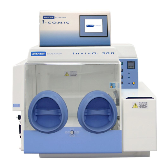
Invivo Product Summary Baker Ruskinn's Invivo hypoxia workstation allows you to isolate cells in a chamber that accurately maintains and controls temperature, humidity, oxygen and carbon dioxide. With the Invivo , you can study even the most complex cell interactions under perfect microaerophilic or anaerobic conditions. -
Page 3: Table Of Contents
Invivo Table of Contents Product Summary ........................... 2 Features and Benefits ..........................2 Overview ............................ 6 Safety Instructions ......................6 Regulatory compliance ....................7 Symbols ......................... 7 Installation and relocation .................... 8 Weight and dimensions ....................9 Gas and electrical supply requirement ..................10 Gas supply requirements .................... - Page 4 Invivo Humidity control ......................21 Humidity control overview ................21 Humidistat humidity control ................21 Environmental gas composition control .................. 21 Using the workstation chamber....................22 Using the interlock ...................... 22 Interlock overview ..................22 Opening the interlock outer door ..............22 Opening the interlock inner door ..............
- Page 5 Invivo Filling the pressure relief/ humidifier tank ............. 35 Replacing an Ezee Sleeve ................36 Replacing detox sachets ................. 37 Installing/ replacing a catalyst sachet ............. 38 Replacing the mains plug fuse – UK users only ..........39 Replacing the mains fuses ................40 Service requirements ....................
-
Page 6: Overview
Invivo Overview Please read this manual carefully to familiarise yourself with the operation and maintenance of the Invivo 300 workstation. Note: The workstation should be located in a well-ventilated area. Safety Instructions For your safety, the safety of others using the workstation and those around you; ... -
Page 7: Regulatory Compliance
Invivo Regulatory compliance This product complies with the essential EEA requirements for Electrical Safety and the Low Voltage Directive 2006/95/EC as well as Electromagnetic compatibility as set out in the EMC Directive 204/108/EC. Symbols Before using the Invivo 300, please ensure that you are familiar with the symbols on the Invivo 300. -
Page 8: Installation And Relocation
Invivo Symbol Meaning Warning, this equipment contains high voltage circuitry. Warning: Do not use toxic or Flammable substances inside the incubator. Invivo 300 contains hazardous components and must not be disposed of at a household waste site. Instead it should be taken to the appropriate collection point for the recycling of electrical and electronic equipment. -
Page 9: Weight And Dimensions
Invivo Weight and dimensions The Invivo 300 workstation weighs approximately 75kg. Figure 2 lists the dimensions of the Invivo 300 workstation; Figure 2: Invivo2 300 workstation dimensions External width 830 mm External height 650 mm External depth 660 mm Workstation chamber internal width 500 mm Workstation chamber internal height 420 mm... -
Page 10: Gas And Electrical Supply Requirement
Invivo Gas and electrical supply requirement Gas supply requirements The Invivo 300 workstation requires; Oxygen free nitrogen. In addition to this, the Invivo 300 workstation should be connected to ICO IC (supplied with the Invivo 300 workstation). All other gas connections should be made to the ICO See UM-011 ICO IC user manual for more details. -
Page 11: Powering The Workstation
Invivo Note: The power consumption is for normal operating conditions with no equipment connected to the internal power supply. Power consumption will vary dependent upon the conditions inside the workstation chamber and the conditions inside the room the workstation is located in. Powering the workstation To switch the workstation on, press the power switch (item 2 Figure 14). -
Page 12: Workstation Overview
Invivo Workstation overview Workstation layout The Invivo 300 workstation consists of 2 main areas; the workstation chamber and the interlock chamber. The workstation chamber is the main working area of the workstation. Access to the workstation chamber is provided by the glove ports, the Single Plate Entry System (SPES) and the interlock. -
Page 13: Rear View
Invivo Rear view Figure 5 shows the rear view of the Invivo 300 workstation; Figure 5: Invivo2 300 workstation rear view UM-010 R4.0 Page 13 of 48 Invivo 300 User Manual... -
Page 14: Left Side View - Standard Humidifier
Invivo Left side view – Standard humidifier Figure 6 shows the left side view of the Invivo 300 workstation with the standard humidifier; Figure 6: Invivo2 300 workstation left side view 1. Pressure relief tank cover (pressure relief tank bung). 2. -
Page 15: Left Side View - Ultrasonic Humidifier
Invivo Left side view – Ultrasonic humidifier Figure 7 shows the left side view of the Invivo 300 workstation with the ultrasonic humidifier; Figure 7: Invivo2 300 workstation left side view with ultrasonic humidifier 1. Exhaust valve outlet 2. Cable gland (optional extra) 3. -
Page 16: Right Side View
Invivo Right side view Figure 8 shows the right side view of the Invivo 300 workstation; Figure 8: Invivo2 300 workstation right side view 1. Mixed gas inlet. 2. Sample gas return. 3. Sample gas out. 4. Serial number label. 5. -
Page 17: Control System Layout
Invivo Control system layout The control system layout varies by model. Please familiarise yourself with the control system layout of your Invivo 300 workstation. Control panel Figure 9 shows the control panel of the Invivo 300 workstation; Figure 9: Invivo2 300 workstation control panel 1. -
Page 18: Temperature Controller
Invivo Temperature controller Figure 10 shows the temperature controller; Figure 10: Temperature controller 1. Not user accessible (For service personnel only) 2. Not user accessible (For service personnel only) 3. Number scrolling button. Use to move across digits. Use with buttons 4 &... -
Page 19: Interlock Inner Door Control Panel
Invivo Interlock inner door control panel Figure 12 shows the interlock inner door control panel; Figure 12: Interlock inner door control panel 1. Inner door LED indicator. Illuminates to indicate when the interlock inner door is available. 2. Inner door button. Press to unlock the interlock inner door (when available). Foot switch control panel Figure 13 shows the foot switch controller which is used to operate the spot light, vacuum control and interlock purge control. -
Page 20: Power Entry Panel
Invivo Power entry panel Figure 14 shows the power entry panel and label; Figure 14: Power entry panel 1. Mains fuse holder. 2. On/ off switch. 3. Mains lead connection. 4. Nitrogen inlet 5. Primary earth stud. 6. ICO IC Gas mixer umbilical connection. UM-010 R4.0 Page 20 of 48 Invivo... -
Page 21: Temperature And Humidity Control
Invivo Temperature and humidity control Temperature control The Invivo 300 workstation can control the workstation chamber temperature between ambient plus C and 45 The temperature in the main chamber can be set using the temperature controller on the control panel. Setting the temperature;... -
Page 22: Using The Workstation Chamber
Invivo Using the workstation chamber Using the interlock The Invivo 300 workstation has a 6.5 litre interlock for transferring materials and samples into and out of the workstation chamber. Interlock overview The interlock consists of 3 main components; Interlock outer door ... -
Page 23: Opening The Interlock Inner Door
Invivo Opening the interlock inner door To open the interlock inner door; Access the workstation chamber via the Ezee Sleeves. See section 6.2.2 for details. Press the interlock inner door button (item 2 in Figure 12). Slide the interlock inner door backwards to open. To close the interlock inner door, slide the door forwards. -
Page 24: Hand Access To The Main Chamber
Invivo Hand access to the main chamber Direct hand access to the workstation chamber is provided via the glove ports and the Ezee Sleeve system. The Ezee Sleeves provide direct bare hand (or gloved) access to the workstation chamber. The glove ports and Ezee Sleeves can be used in 3 ways; ... -
Page 25: Entering The Workstation Chamber Using The Ezee Sleeves
Invivo Entering the workstation chamber using the Ezee Sleeves To enter the workstation via the Ezee Sleeves; Set the glove port selector switch (Figure 11) to the correct position for the desired hand entry (Figure 16). Hold the desired Ezee Sleeve cuff with the opposite hand. ... -
Page 26: Exiting The Workstation Chamber Using The Ezee Sleeves
Invivo Figure 18: Glove port cover holder Exiting the workstation chamber using the Ezee Sleeves To exit the workstation chamber using the Ezee Sleeves; Remove the glove port cover from the glove port cover holder (Figure 18). Holding the glove port cover by the glove port cover knob, slowly pull the glove port cover into the glove port with the glove port bar horizontal. -
Page 27: Single Plate Entry System (Spes)
Invivo Single Plate Entry System (SPES) A SPES is provided for quick and easy direct access to the workstation chamber, for loading materials. The SPES is also known as the mailbox. SPES overview The SPES consists of an external hinged flap and an internal hinged flap. The external flap is held in place by a thumb screw when not in use. -
Page 28: Internal Power Socket
Invivo To use the SPES; Undo the thumb screw on the external flap (item 1 in Figure 19) Whilst supporting the SPES external flap, swing the thumb screw to the left. Lower the SPES external flap. Figure 21 shows the SPES when opened; Figure 21: SPES with external hinged flap opened ... -
Page 29: Rear Shelf
Invivo Main chamber light. Spot light. To switch the main chamber light on, press the chamber light switch (item 2 in Figure 9). To switch the main chamber light off, press the chamber light switch (item 2 in Figure 9). To switch the spotlight on, press and hold the spot pedal on the foot switch control panel (item 3 in Figure 13). -
Page 30: Optional Extras
Invivo Optional extras The Invivo 300 workstation may be fitted with optional extra parts to provide added functionality. The available optional extra parts for Invivo 300 workstations are; Cable gland port. Universal gland port. Gas sample port. ... -
Page 31: Gas Sample Port
Invivo Gas sample port The gas sample port can be used to collect a gas sample from the workstation chamber. To use the gas sample port; Remove the outer cap. Push a needle connected to a syringe through the internal sponge of the gas sample port. ... -
Page 32: Online Video User Guides
Invivo Online video user guides Further information and demonstrations can be found at Ruskinn Technology Limited’s YouTube channel; http://www.youtube.com/ruskinntechnology Video demonstrations are available for; Entering and exiting the workstation chamber via the Ezee Sleeves. Setting oxygen and carbon dioxide values. ... -
Page 33: Cleaning And Maintenance
Invivo Cleaning and maintenance Cleaning the workstation To ensure that your Invivo 300 workstation remains at optimum working conditions, it must be cleaned on a regular basis. A basic clean is required after each use. Deep cleaning is required at regular intervals, dependent upon the nature of the materials used in the workstation. -
Page 34: Cleaning Procedure - Deep Clean
Invivo Cleaning procedure – deep clean To deep clean the workstation; Preparing the workstation Return the ICO IC to the main menu (see UM-011 for more information). Remove all cells/ samples to an alternative storage facility. Switch the workstation off at the mains and remove the plug from the mains. ... -
Page 35: Maintaining The Workstation - End User Maintenance
Invivo Maintaining the workstation – End user maintenance To ensure that your Invivo 300 workstation remains at optimum working conditions, it must be maintained on a regular basis. Many basic tasks can be performed by the end user. Filling the pressure relief/ humidifier tank The pressure relief/ humidifier tank requires refilling if the water level is on or below the low level indication. -
Page 36: Replacing An Ezee Sleeve
Invivo Replacing an Ezee Sleeve To remove an Ezee Sleeve; Ensure that the glove port covers are closed. Remove the O-rings that hold the Ezee Sleeve to the glove port. Note: The O-rings will be tight. Figure 28 shows the O-ring removal; Figure 28: O-ring removal ... -
Page 37: Replacing Detox Sachets
Invivo Replacing detox sachets Detox sachets are supplied with the Invivo 300 workstation. The detox sachets adsorb volatile organic compounds, improving the air quality within the workstation chamber. Detox sachets need to be replaced annually. See section 7.4.2 for ordering details. To replace the detox sachets;... -
Page 38: Installing/ Replacing A Catalyst Sachet
Invivo Lower the floor tray, ensuring that the floor tray leg has located in the floor tray locator (item 3 in Figure 29). Close the glove ports using the glove port covers. Reinstall the Ezee Sleeves (see section 0 for more details). ... -
Page 39: Replacing The Mains Plug Fuse - Uk Users Only
Invivo Replacing the mains plug fuse – UK users only To replace the mains plug fuse; Remove the plug from the mains socket. Using a small flat bladed screw driver, remove the fuse cover from the mains plug. Figure 30 shows the fuse removal;... -
Page 40: Replacing The Mains Fuses
Invivo Replacing the mains fuses To replace the mains fuses; Switch off the Invivo 300. Remove the plug from the mains socket. Remove the mains fuse drawer using a small flat bladed screwdriver. Figure 31 shows the removal of the mains fuse holder;... -
Page 41: Service Requirements
Invivo Service requirements To maintain the best performance from your Invivo 300 workstation, it must be serviced at regular intervals. Figure 32 lists the servicing requirements, intervals and persons capable of performing the service; Figure 32: Invivo2 300 servicing requirements Action Frequency Clean workstation... -
Page 42: Spare Parts And Cleaning Agents
Invivo Spare parts and cleaning agents Figure 33 lists the spare parts and cleaning agents available for your Invivo 300 workstation. To order spare parts, please contact your local distributor for the latest pricing and availability. All items are sold individually except where stated. Figure 33: Invivo2 300 end user spare parts and cleaning agents list Part Where used... -
Page 43: Workstation Malfunction
Invivo Workstation malfunction In the event of a workstation malfunction, please check section 7.6.1 for a list of common problems and solutions. If you cannot find a solution to your problem, please contact your local distributor, quoting the serial number of your workstation. If the problem is related to the ICO IC, please contact your local distributor. -
Page 44: Interlock Problems
Invivo Interlock problems Figure 36 gives a list of common interlock problems and solutions; Figure 36: Interlock problems and solutions Problem Cause Solution The interlock inner interlock inner Check for obstructions to closing the interlock door will not close door is blocked inner door and remove them The interlock is purging Wait for the interlock purge cycle to finish... -
Page 45: Gas Mixer And Gas Consumption Problems
Invivo Gas mixer and gas consumption problems The Invivo 300 workstation is fitted with a gas demand indicator (item 7 in Figure 9). When the gas demand indicator is illuminated, the pressure is low in the workstation chamber. A shot of gas will be injected into the workstation to raise the pressure in the workstation chamber. -
Page 46: Warranty Information
Invivo Warranty information Ruskinn Technology Limited warrants for the applicable time period that the Invivo 300 will substantially perform in accordance with the user documentation. The terms of this Agreement do not affect or prejudice the statutory rights of a consumer acquiring the Ruskinn Technology Limited Invivo otherwise than in the normal course of a business. -
Page 47: Disposal Information
Invivo Disposal information Invivo 300 contains hazardous components and must not be disposed of at a household waste site. Instead it should be taken to the appropriate collection point for the recycling of electrical and electronic equipment. Alternatively, please contact your local distributor for disposal instructions. Invivo 300 contains recyclable parts. - Page 48 Ruskinn Technology Limited is a registered company in United Kingdom, company number 05692599 Ruskinn Technology Limited is VAT registered in United Kingdom, VAT number 870194126 Ruskinn Technology Limited is a wholly owned subsidiary of the Baker Company UM-010 R4.0 Page 48 of 48...
Need help?
Do you have a question about the Invivo2 300 UM-010 and is the answer not in the manual?
Questions and answers