Table of Contents
Advertisement
Quick Links
Advertisement
Table of Contents

Subscribe to Our Youtube Channel
Related Manuals for Stentofon 1401110100


Summary of Contents for Stentofon 1401110100
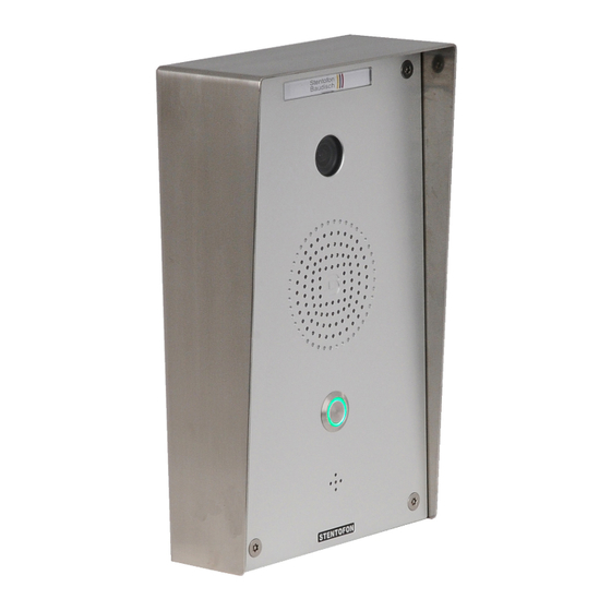
- Page 1 Vandal Resistant IP Video Station CONFIGURATION MANUAL A100K11377...
- Page 2 Document Scope i do u ent de ri e t e onfiguration and etu o t e IP Video Station Product Item No. Vandal Resistant IP Video Station 1401110100 Flush Mount Back Box 1401199101 Surface Mount Back Box 1401199111 Protective Roof...
-
Page 3: Table Of Contents
Contents 1 Introduction ....................4 Produ t e ri tion S te er ie 2 Starting Up The System ................5 e ault a tor Setting ard are Pre etting Conne tor oard Conne ting t e IP Video Station 3 IP Video Station Configuration ..............7 Preli inar e uire ent IP Station Configuration... -
Page 4: Introduction
▪ utton it i olor ring 1.2 System Overview Video Ca era i STENTOFON Pul e SIP IP Network SIP Phone AlphaCom XE7 Ser er ener ela ternal utton IP Video Station... -
Page 5: Starting Up The System
4.1.Preconfiguration Starting Up The System IP Video oorStation a i ed IP addre e deli er IP Su Station it 2.1 Default Factory Settings IP Ca era IP Video Station a de ault IP addre e on deli er ▪ IP Station 169.254.1.100 4.2.Presettings Hardware ▪... - Page 6 Connection Option 1: Switch with PoE ▪ Conne t t e Po it a net or a le to t e ort P on t e tation Connection Option 2: Switch without PoE ▪ Conne t a V C o er u e ured to V o t e P ter inal lo on t e tation...
-
Page 7: Ip Video Station Configuration
IP Video Station Configuration 3.1 Preliminary Requirements ▪ t ernet or onne ting t e IP Video Station ▪ le tri al Po Standard o er u 3.2 IP Station Configuration 3.2.1 Log into the Web Interface e tation eature an e edded e inter a e allo u er to log in ia a tandard e... -
Page 8: Station Mode And Ip Setting
3.2.2 Station Mode and IP Settings ▪ Station Main > Main Settings to a e t e age or onfiguring tation ode and IP ara eter Station Mode ▪ Use Alphacom radio utton e IP Station or a an l inter o tation nder egi tration Setting... -
Page 9: Eneral D Ini Tration
3.2.3 General Administration ▪ Sele t Station Administration Reboot ▪ e oot ard are re oot o t e IP Station ▪ e oot ain a li ation are re tart o t e IP Station Logging la o ariou e age Licensing entering li en e e... - Page 10 Manual Upgrade o arr out a o t are u grade ro eed a ollo ▪ o nload t e late t i age file or t e IP Station ro t e enitel ort e a i i ▪ Start a P er er on our PC P er er an e...
-
Page 11: Udio Setting
3.2.4 Audio Settings ▪ Sele t Advanced Configuration > Audio ro Handset Volume ▪ Volu e o t e internal ea er Noise Reduction Levels ▪ e el ean t at noi e redu tion i di a led ▪ e el gi e a a i u noi e redu tion o... -
Page 12: Erating A Sip Client
3.2.5 Operating as SIP Client ▪ Station Main > Main Settings to a e t e age or onfiguring tation ode and IP ara eter Station Mode ▪ Sele t t e Use SIP radio utton ▪ I ne e ar ad u t t e etting under IP Settings ▪... - Page 13 Directory Number (SIP ID) i i t e identifi ation o t e tation in t e SIP do ain i e t e one nu er or t e tation ara eter i andator nter t e SIP I in integer a ording to t e SIP a ount on t e SIP do ain er er Server Domain (SIP) ara eter i...
- Page 14 Disable Disconnect By Button n e i ting oi e o uni ation an not e ended re ing t e all utton o t e IP Video Station C e t e o to ena le t i un tion Overlap dialing ill lead to t e one tarting to dial ea...
- Page 15 Remote Controlled Volume Override Mode a ti ating t i un tion t e oi e dire tion an e et re ing ertain utton during an e i ting oi e o uni ation re ing t e a teri utton on t e one t e...
- Page 16 ▪ e tandard un tion o t e In ut utton i Call o and an not e anged ▪ nter t e one nu er in t e field Value ould e dialed a ter re ing t e all utton ▪...
-
Page 17: Erating A Pul E Ser Er
▪ Static IP Sele t t i o tion i t e IP tation all u e a tati IP addre ▪ Save ollo ed Apply 3.2.7 Operating as Pulse Client ▪ Station Main > Main Settings Station Mode ▪ Sele t t e Use Pulse radio utton IP Settings ▪... -
Page 18: Create Sip Client
Licensing 3.2.8.2 Create SIP Clients ▪ Server Management > Server Configuration >Directory Settings nder STENTOFON Stations t e Video Station it el a ell a all a aila le S lient in t e Pul e are di... -
Page 19: E Ault Setting
3.2.9 Default Settings 3.2.9.1 Restore Default Settings with Static IP ile re ing t e all utton o er u t e tation en t e tation tart ing relea e t e all utton after exactly 1 flash et t e or exactly 2 more times t en re t e utton again... -
Page 20: Ip Setting
3.2.11 IP Settings ▪ System Settings er na e ad in ▪ Network in t e le t Common ▪ ti ation dea ti ation o re ote a e P on t e file o t e IP Ca era ▪... -
Page 21: Er Manage Ent
3.2.12 Camera Settings ▪ System Settings er na e ad in ▪ Camera in t e le t Settings ▪ Configuration Pre et C oi e o onfiguration te late or t e a era etting e ault Pre et i ▪... -
Page 22: I Age Video I La
o delete a u er ro eed a ollo ▪ Sele t Delete User ▪ Sele t t e u er ou ant to delete ▪ Delete User 3.2.14 Image / Video Display In t e e inter a e it i o i le to di la t e i age o t e a era a a lide... - Page 23 ▪ ig t li t e rogra i on to o en t e onfiguration Minimize e di la ed ideo i age are ini i ed en t e onfiguration i et to ll uto Po t e ideo indo reo en en t ere a all Maximize e ideo i age are di...
- Page 24 nter t e ollo ing in or ation under t e Camera ta ▪ Modulena e ign a na e or t e a era e g ain entran e ▪ IP addre e IP addre o t e a era ▪...
-
Page 25: Configuring T E Ip Ca Era
3.2.15.2 Configuring the IP Camera ▪ og into t e e inter a e o t e IP Ca era ▪ System Settings er ad in ▪ Network nder Ports t e ollo ing ara eter ould e et ▪ uto ati Ca ete tion 4005 ▪... - Page 26 ▪ e 8 - Conversation - Outgoing ▪ en C ange o ON or OFF ▪ tion Co and or C IND %1p 2 1 1 3.2.16 Example Configuration of snom IP Telephone with Image Transmission e i age o t e IP Ca era an e o n on t e di la o a no tele...
- Page 27 e ollo ing etting are re uired ▪ Identit a ti e on ▪ la na e an na e o t e SIP er er e g Pul e Ser er ▪ ount SIP I ogin na e e g ▪...
-
Page 28: Board Connections
STENTOFON.IP VideoDoorStation Board Connections Ver ion Stand The IP Video Station should not be operated with power supply voltages of ~230VAC. If this is not complied with, and there is no grounding, the station may be damaged, and electrical power on the housing may be a danger to life. - Page 29 STENTOFON.IP VideoDoorStation 4.2 Connections for Hardware Version 0.2/0.3/1.0 Ver ion Stand 6.3.2. View of the Connections Hardware Version 0.2/0.3/1.0 Station oard Station oard LAN Port LS- (Pin 1) Relay Relay 0V (Ext) 24V (Ext) Conne tor oard LED ON I LED...
- Page 30 4.3 Connections On Boards STENTOFON.IP VideoDoorStation Ver ion Stand Connection Name Description S ea er alread onne ted (Station Board) Potential ree rela onta t Clo er ternal oltage u ttention not i ultaneou l it Po rounding or illu ination...
- Page 31 Ver ion Stand Connection Name Description rounding or illu ination (Connector a ground illu ination Board V0.2) 1st button 2nd button e eren e oint utton (Connector Board V0.1) a ground illu ination rounding or illu ination (Connector Board V0.2) 1st button 2nd button 3th button...
-
Page 32: Operating States Indication Leds
Indi ator Operating States Indication LEDs e Video oorStation indi ate di erent tate e eral on t e Su Station it e Video Station indi ate di erent tate on e eral on t e 6.3.3. Connections and Operating States Station oard on t e a The STATUS LED is a bicolored SMD LED and displays the... - Page 33 LAN LEDs on RJ45 ports Left LED Stead lig t t ernet onne tion t ernet tra fi o lig t o t ernet onne tion Right LED Stead ig t M it t ernet onne tion o lig t M it t ernet onne tion A100K11377 IP Video Station Configuration Manual...
-
Page 34: Product Specifications
1 Relay output IP protocols IP v4 - TCP - UDP - HTTPS – TFTP - RTP - RTCP -DHCP - SNMP - DiffServ - TOS – STENTOFON CCoIP® - SIP LAN protocols Power over Ethernet (IEEE 802.3 a-f), VLAN (IEEE 802.1pq)*, Network Access Control (IEEE 802.1x)*, STP (IEEE 802.1d),... -
Page 35: Station I En Ion
6.2 Station Dimensions STENTOFON.IP-VideoDoorStation Version 0.3 - Stand: 10.01.2013 A100K11377 IP Video Station Configuration Manual Bei der Montage, Demontage ist insbesondere bei der Hardwareversion V0.1 darauf zu achten,... - Page 36 6.3 Back Boxes / Protective Roof Mount a Sur a e Mount a Prote ti e oo A100K11377 IP Video Station Configuration Manual...
- Page 37 A100K11377 IP Video Station Configuration Manual...
- Page 38 A100K11377 Zenitel and its subsidiaries assume no responsibility for any errors that may appear in this publication, or for damages arising from the information therein. STENTOFON and VINGTOR products are developed and marketed by Zenitel. The company’s Quality Assurance System is certified to meet the requirements in NS-EN ISO 9001. Zenitel reserves the right to modify designs and alter specifications without notice.
Need help?
Do you have a question about the 1401110100 and is the answer not in the manual?
Questions and answers