Table of Contents
Advertisement
Quick Links
Advertisement
Table of Contents

Subscribe to Our Youtube Channel
Related Manuals for Alfa Laval LKAP


Summary of Contents for Alfa Laval LKAP
- Page 1 Instruction Manual LKAP Air-Operated Valve ESE01993-EN6 2016-07 Original manual...
-
Page 3: Table Of Contents
4.3. Recommended cleaning ................. 5. Maintenance ................... 5.1. General maintenance ................5.2. Dismantling ..................5.3. Assembly ..................6. Technical data ..................6.1. Technical data ..................7. Parts list and service kits ................7.1. LKAP-V and LKAP-T air-operated valves with welding ends ......... -
Page 4: Ec Declaration Of Conformity
1 EC Declaration of conformity Revision of Declaration of Conformity 2009-12-29 The Designated Company Alfa Laval Kolding A/S Company Name Albuen 31, DK-6000 Kolding, Denmark Address +45 79 32 22 00 Phone No. hereby declare that Valve Designation LKAP Type... -
Page 5: Safety
2 Safety Unsafe practices and other important information are emphasized in this manual. Warnings are emphasized by means of special signs. 2.1 Important information Always read the manual before using the valve! WARNING Indicates that special procedures must be followed to avoid serious personal injury. CAUTION Indicates that special procedures must be followed to avoid damage to the valve. -
Page 6: Safety Precautions
2 Safety All warnings in the manual are summarized on this page. Pay special attention to the instructions below so that severe personal injury and/or damage to the valve are avoided. 2.3 Safety precautions Installation: Always observe the technical data (see section 6 Technical data) Always release compressed air after use. -
Page 7: Installation
Check the delivery: CAUTION 1. Complete valve, LKAP-V or LKAP-T 2. Delivery note Alfa Laval cannot be held responsible for incorrect unpacking. 3. Instruction manual Step 2 1. Clean the valve for possible packing materials 2. Inspect the valve for visible transport damage 3. - Page 8 3 Installation Study the instructions carefully and pay special attention to the warnings! The valve has welding ends as standard but can also be supplied with fittings. NO = Normally open. NC = Normally closed. Step 4 Fittings: Ensure that the connections are tight (remember seal rings). TD402-019_1 Step 5 Air connection: R 1/8”...
-
Page 9: Welding
3 Installation Study the instructions carefully. The items refer to the drawings and the parts list in section 7 Parts list and service kits. Check the valve for smooth operation after welding. 3.3 Welding Step 1 1. Turn air cylinder (2) anticlockwise by hand with a strap wrench or with a spanner. -
Page 10: Recycling Information
- At end of use, the equipment shall be recycled according to relevant, local regulations. Beside the equipment itself, any hazardous residues from the process liquid must be considered and death with in a proper manner. When in doubt, or in the absence of local regulations, please contact the local Alfa Laval sales company. -
Page 11: Operation
The items refer to the drawings and the parts list in section 7 Parts list and service kits 4.1 General operation Step 1 CAUTION Alfa Laval cannot be held responsible for incorrect operation. Always read the technical data thoroughly. (see section 6 Technical data) Always release compressed air after use. -
Page 12: Recommended Cleaning
4 Operation The valve is designed for cleaning in place (CIP). CIP = Cleaning In Place. Study the instructions carefully and pay special attention to the warnings! NaOH = Caustic Soda. HNO3 = Nitric acid. 4.3 Recommended cleaning Step 1 Caustic danger! Always handle lye and acid with great care. -
Page 13: Maintenance
5 Maintenance Maintain the valve and the actuator carefully. Study the instructions carefully and pay special attention to the warnings! Always keep service kits in stock. Check the valve for smooth operation after service. 5.1 General maintenance Step 1 NOTE All scrap must be stored/discharged in accordance with current rules/directives. -
Page 14: Dismantling
5 Maintenance Study the instructions carefully. The items refer to the drawings and the parts list in section 7 Parts list and service kits 5.2 Dismantling Step 1 1. Turn air cylinder (2) anticlockwise by hand with a strap wrench or with a spanner 2. - Page 15 5 Maintenance Study the instructions carefully. The items refer to the drawings and the parts list in section 7 Parts list and service kits Step 4 1. Separate piston (6) from valve plug unit (12, 14) 2. Pull off O-ring (7) from the piston Step 5 1.
-
Page 16: Assembly
5 Maintenance Study the instructions carefully. The items refer to the drawings and the parts list in section 7 Parts list and service kits. Lubricate the rubber seals before fitting them. Step 7 1. Remove hollow spindle (12) from valve spindle (14) 2. - Page 17 5 Maintenance Study the instructions carefully. The items refer to the drawings and the parts list in section 7 Parts list and service kits. Lubricate the rubber seals before fitting them. Step 3 1. Fit O-rings (8, 9) into the grooves of bottom piece (10) 2.
- Page 18 5 Maintenance Study the instructions carefully. The items refer to the drawings and the parts list in section 7 Parts list and service kits. Lubricate the rubber seals before fitting them. Step 6 1. Position spring (5) in the groove of piston (6) 2.
-
Page 19: Technical Data
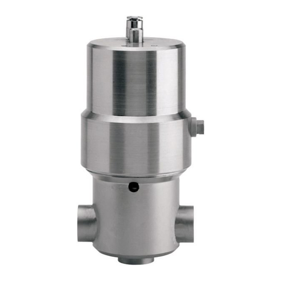
The valve is operated by means of compressed air and has spring return. It has few and simple moving parts which results in a very reliable valve. Standard Design LKAP consists of actuator with air cylinder and piston, double lipseal for stem, stem unit with replaceable O-ring in the plug, and valve body with welding connections. -
Page 21: Parts List And Service Kits
7 Parts list and service kits It is important to observe the technical data during installation, operation and maintenance. Inform the personnel about the technical data. NO = Normally open. NC = Normally closed. -
Page 22: Lkap-V And Lkap-T Air-Operated Valves With Welding Ends
7 Parts list and service kits It is important to observe the technical data during installation, operation and maintenance. Inform the personnel about the technical data. NO = Normally open. NC = Normally closed. 7.1 LKAP-V and LKAP-T air-operated valves with welding ends TD 402-043_1... - Page 23 7 Parts list and service kits It is important to observe the technical data during installation, operation and maintenance. Inform the personnel about the technical data. NO = Normally open. NC = Normally closed. Parts list Pos. Denomination Plug Pointed screw Air cylinder Air cylinder ...
- Page 24 © Alfa Laval Corporate AB This document and its contents is owned by Alfa Laval Corporate AB and protected by laws governing intellectual property and thereto related rights. It is the responsibility of the user of this document to comply with all applicable intellectual property laws. Without limiting any rights related to this document, no part of this document may be copied, reproduced or transmitted in any form or by any means (electronic, mechanical, photocopying, recording, or otherwise), or for any purpose, without the expressed permission of Alfa Laval Corporate AB.
Need help?
Do you have a question about the LKAP and is the answer not in the manual?
Questions and answers