Table of Contents
Advertisement
Advertisement
Table of Contents

Related Manuals for Moehlenhoff Alpha IP


Summary of Contents for Moehlenhoff Alpha IP
- Page 1 Alpha IP RTD 61001-N1 132713.1628...
- Page 2 M3 x 30 mm 5 mm...
- Page 3 ~ 30 cm ~150 cm...
-
Page 6: Table Of Contents
Intended use Safety notes 3 Function 4 Device overview Technical data 5 Commissioning Teaching the device 5.1.1 Teaching to Alpha IP Base Station 5.1.2 Teaching-in to Alpha IP Access Point Installation 5.2.1 On-surface installation 5.2.2 Installation in flush-type box 5.2.3... - Page 7 6.1.7 Offset temperature 6.1.8 Selection of temperature display/humidity 6.1.9 Configuration of Alpha IP Base station 6.1.10 Connection test 7 Operation 8 Displays Status indications Error indications 9 Changing the batteries 10 Cleaning Restoring the factory settings 12 Decommissioning 13 Disposal...
-
Page 8: About These Instructions
These instructions must be kept and to be handed over to future users. The latest version of these instructions/of Additional Alpha IP System infor- mation can be found under www.alphaip.de. System information, functions and operating steps from the instructions for Alpha IP Access Point (HAP 21001) must be observed. -
Page 9: Safety
• the registration of the actual temperature (room temperature) and the humidity, • the setting of the target temperature (comfort temperature), • the control of the actual temperature by an activation of the Alpha IP Base sta- tion for the control of floor heating systems (FAL-x10x1-xx1) or connected Alpha IP radiator thermostats, •... -
Page 10: Function
3 Function The Alpha IP room control unit Display RTD 61001-N1 allows to set the room tem- perature in a time-controlled way in order to adapt the heating phases to your indi- vidual requirements. The room control unit measures the temperature and transmits these data cyclically to the Alpha IP Base station FAL-x10x1-xx1 or to connected Alpha IP radiator thermostats. -
Page 11: Device Overview
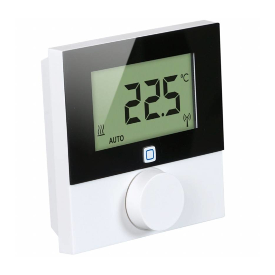
Device overview 4 Device overview Device overview (see page 4 fig. 1) Installation bottom Room control unit Display Display System button (teaching button and LED) Removable setting wheel Display overview (see fig. 1) Fig. 1: Display overview Automatic operation Target/actual temperature and humidity Holiday mode Condensation warning... -
Page 12: Technical Data
Function 4.1 Technical data Short designation of RTD 61001-N1 device Supply voltage 2x 1.5 V LR03/micro/AAA Power consumption max. 50 mA Battery service life 2 years (normally) Protection type IP20 Contamination degree Ambient temperature 0 to 50 °C Dimensions (W x H x D) 86 x 86 x 21.6 mm / 26.5 mm Weight 110 g (including batteries) -
Page 13: Commissioning
If no teaching-in is performed, the teach-in mode is finished automatically after 30 seconds. If the room control unit shall be taught-in to the Alpha IP Base station, the two devices to be linked must be set to teach-in mode. -
Page 14: Teaching-In To Alpha Ip Access Point
For a control via the Alpha IP app, the teaching-in must of the RTD 61001-N1 must be performed via the Access Point (HAP 21001). Teach-in the device as follows: Ö The Alpha IP Access Point has been set up via the Alpha IP App (see instructions HAP 21001). -
Page 15: Installation
Commissioning 5. The device is displayed automatically in the Alpha IP app. 6. Enter the last four ciphers of the device number (SGTIN) or scan the supplied QR code for confirmation. The device number can be found below the QR code or in the battery compartment. -
Page 16: Installation In Flush-Type Box
Commissioning If wood walls are present, the screws can be screwed directly into the wood. Pre-drilling with a 1.5 mm wood drill can facilitate the installation of the screws. 6. For stone walls, drill the holes at the marked positions with a 5 mm masonry drill. 7. -
Page 17: Installation With Adhesive Strips
Commissioning 5.2.3 Installation with adhesive strips Depending on the ground, installation can be performed using the supplied dou- ble-sided adhesive tapes. Installation is possible on different grounds, as e. g. ma- sonry, furniture, tiles or glass. 1. Select an appropriate installation position. If the installation is done with adhesive strips, the installation surface must be smooth, level, undamaged, clean, and free from grease and solvents. -
Page 18: Operating Modes And Configuration
6 Operating modes and configuration The setting wheel E (see page 4 fig. 1) provides the operating functions of the de- vice. Depending on the configuration, the settings are transmitted to the Alpha IP Base station or to the Alpha IP app. -
Page 19: Automatic Mode
Operating modes and configuration 6.1.1 Automatic mode Do the following to activate automatic operation: 1. Press and hold the setting wheel (E) in order to open the configuration menu. 2. Select the symbol “ “ and confirm the selection by shortly pressing the setting wheel. -
Page 20: Operating Lock
Operating modes and configuration 6.1.4 Operating lock The operation at the device can be locked in order to prevent the unintentional change of settings e. g. by accidental touch. Proceed as follows in order to activate or deactivate the operation lock: 1. - Page 21 Operating modes and configuration “Pr.Ad” for the individual setting of the week profiles („no. 1, no. 2 ... no. 6“). Up to 6 heating phases (13 switch-over points) can be set in the week profile for every week day for the selected heating profile. Programming is made for the selected days for the time from 00:00 to 23:59 o’clock.
-
Page 22: Setting Date And Time
Operating modes and configuration 6.1.6 Setting date and time 1. Press and hold the setting wheel (E) in order to open the configuration menu. 2. Select the symbol “ “ and confirm the selection by shortly pressing the setting wheel. 3. -
Page 23: Configuration Of Alpha Ip Base Station
The device parameters “UnP1/UnP2” and the channel parameters “ChAn” are avail- able in the configuration menu for the Alpha IP Base station; these parameters allow the modification of the pump lead and follow-up times, setback temperatures, time intervals and many other parameters. -
Page 24: Operation
In automatic operation, the heating profile set with the Alpha IP app is active. In manual op- eration, the temperature can be set at the device or using the app, and remains until the next manual change is made. -
Page 25: Displays
Displays 8 Displays 8.1 Status indications Display Meaning Meaning Humidity limit Ventilate room flashes (standard: 60 %) in the room exceeded Humidity input activat- Ventilate room flash ed at Multi IO Box Operating lock active flashes Short flashing in orange Radio transmission/ Wait until the transmission Transmission attempt/... -
Page 26: Error Indications
8.2 Error indications Display Meaning Solution Battery voltage low. Change the batteries. Bad connection to Check the connection. (flashes) the Alpha IP Access Point Short illumination in Batteries dead Change the batteries. orange (after reception signal) Long illumination in red Transmission error,... -
Page 27: Changing The Batteries
Cleaning 9 Changing the batteries The symbol in the display and in the Alpha IP app indicates low battery voltage. Replacing the batteries: 1. Take off the device from the installation bottom (see page 5, fig. 4). 2. Remove the batteries from the back side. -
Page 28: Restoring The Factory Settings
Restoring the factory settings 11 Restoring the factory settings The reset to factory setting will delete all settings made by the user. 1. Take off the device from the installation bottom (see page 5, fig. 4). 2. Remove the batteries. 3. -
Page 29: Decommissioning
Disposal 12 Decommissioning 1. Take off the room control unit Display from the installation bottom (see page 5 fig. 6). 2. Remove the batteries from the back side. 3. Uninstall the device and dispose of properly. 13 Disposal The device must not be disposed with domestic waste. The operator has the duty to hand the device to a suitable collection point. - Page 30 132713.1628...
Need help?
Do you have a question about the Alpha IP and is the answer not in the manual?
Questions and answers