
Related Manuals for Jema Autolifte JA4000F


Summary of Contents for Jema Autolifte JA4000F
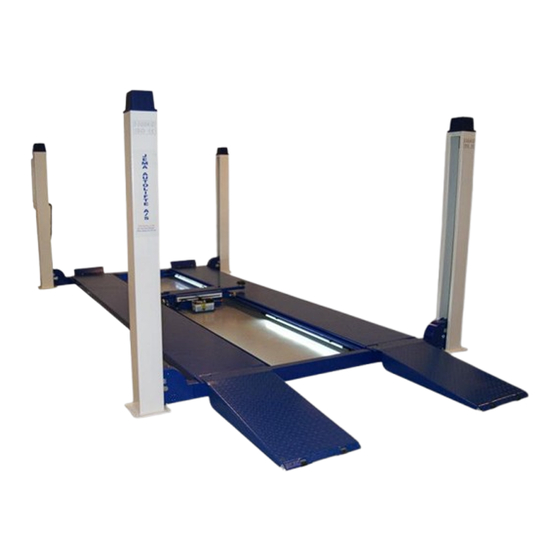
- Page 1 Jema Autolifte A/S JA4000F FOUR POST LIFT Electrical Release INSTALLTION, OPERATION AND MAINTENANCE MANUAL Read this entire manual carefully and completely before installation and operation of the lift.
-
Page 2: Table Of Contents
INDEX 1. Important safety instructions……………………………….…..5~7 1.1 Important notices 1.2 Qualified personnel 1.3 Danger notices 1.4 Warning signs 1.5 Sound level 1.6 Training 2. Overview of the lift……………………………………………….……..7~8 2.1 General descriptions 2.2 Construction of the lift 2.3 Optional parts 3. Installation instructions………………………………………….……8~11 3.1 Preparations before installation 3.1.1 Tools and equipments needed 3.1.2 A list for parts checking... - Page 3 User’s Records Fill the following blanks with the information on the nameplate. Model No. ____________________________ Serial No.___________________________ Production Date ______________________ The following specially trained people are permitted to operate and maintain this lift.
- Page 4 Installation Records Model No. _________________________ Serial No. _ _ ____________________ _ __ Customer’s Name: ______________________ ___ _ _ _ Installation Date: __________________ ________ _ _ Declaration The above mentioned lift has been correctly installed and all its functions including the reliability of safety locks have passed strict tests. Therefore we hereby declare that this lift is in normal working condition when installation finished.
-
Page 5: Important Notices
1.1 Important notices Jema autolifte A/S will offer one-year's quality warranty for the whole machine,during which any quality problem will be properly solved to the user's satisfaction. However, we will not take any responsibility for whatever bad consequence resulted from improper installation and operation, overload running or unqualified ground condition. -
Page 6: Warning Signs
1.4 Warnings (Read and understand all safety warnings before operation) All safety warning signs attached on the lift are for the purpose of drawing the user’s attention to safety operation. The labels must be kept clean and need to be replaced when they are worn-out or have dropped. Read the explanations of the labels carefully and try to memorize them. -
Page 7: Sound Level
1.5 Sound Level The sound emitted from the lift should not exceed 75DB. For the sake of your health, we suggest putting a noise detector in your working area. 1.6 Training Only properly trained people are allowed to operate the lift. We are quite willing to provide professional training for the users when necessary. -
Page 8: Optional Parts
Unfold the package and check if any parts missed as per Annex 1. Do not hesitate to contact us in case any parts missed, but if you do not contact us and insist installing upon the lack of some parts, Jema Autolifte A/S as well as our dealers will not bear any responsibility for this and will charge for any parts subsequently demanded by the buyer. -
Page 9: Installation
3.3 Installation instructions Step1: Choose a proper site Location requirement If not specifically stated, our lifts are only for indoor use. It should be fixed on a smooth and solid concrete ground. Do not install this lift on expansion beams of concrete or on a second or an elevated floor without first consulting building architect. Make sure that the space around or over the lift should be free of obstructions like heaters, building supports, electrical lines etc. - Page 10 Step6: Separately insert the four rods of safety teeth fixer into the four ends of cross beams. Please refer to the diagram of safety construction and insert along the inside surface of the post’s blanking plate. Have an M20 nut screwed on the end of the fixer which is to fix the rod of safety teeth fixer.
-
Page 11: Items To Be Checked After Installation
Step 12: Connect the electrical system. Attention: electrical connection must be done by a licensed electrician. Connect the wiring as per the wiring diagram and do pay careful attention to the number tubes attached on each threads of wire. Wires of with the same number shall be connected together. Step 13: Leveling No vehicle on platforms when leveling. -
Page 12: Descriptions Of Control Box
4.1.3 The machine shall not lift or lower an automobile if its center of gravity is not positioned midway of the platforms. Otherwise, Jema Autolifte as well as our dealers will not bear any responsibility for any consequence resulted thereby. -
Page 13: Flow Chart For Operation
4.3 Flow chart for operation Raising Lowering Switch on Switch on Press the UP button Press the DOWN button Motor drives the gear pump work Platforms are lowered The piston goes back to oil cylinder Platforms are raised 4.4 Operation instructions Raise the lift 1. -
Page 14: Emergency Lowering In Case Of No Power
4.5 Emergency lowering in case of no power In the case the safety lock is not fully engaged: 1. Push the front rod of the four electric magnets under the cross beam to have the four safety blocks released from the safety rods. - Page 15 2. Push the front rod of the four electric magnets under the cross beam to have the four safety blocks released from the safety rods. Front rod of electric magnet Safety block and safety rod 3. Press and screw loose counter-clockwise the unloading valve to lower the platform. Unloading valve...
- Page 16 5. Trouble Shooting ATTENTION: If the trouble could not be fixed by yourself, please do not hesitate to contact us for help .We will offer our service at the earliest time we can. By the way, your troubles will be judged and solved much faster if you could provide us more details or pictures of the trouble.
- Page 17 6. Maintenance Easy and low cost routine maintenance can ensure the lift work normally and safely. Following are requirements for routine maintenance. You may decide the frequency of routine maintenance by consulting your lift’s working conditions and time. Name Slider Steel cable Side slider Sliding wheel...
- Page 18 7. Annex Annex1:Packing list of the whole lift Name Drawing#/size Main platform JA4000FN-A4 Assistant platform JA4000FN-A5 Beam A JA4000FM-A2 Beam B JA4000FM-A7 Ramp A JA4000FN-A8 Ramp B JA4000FN-A10 Post JA4000FN-A1-B1 Post JA4000FN-A6-B1 Bar for safety lock JA4000FN-A1-B2 Control box JA4000FC Pump JA4000FM-A3-B33 Slider...
- Page 19 Annex2:Overall diagram...
- Page 20 Annex3:Floor plan Annex 4: Steel cable connection...
- Page 21 Annex 5:Hydraulic working system 1. Oil cylinder 3. Electrical unloading valve 4. Throttle valve 5. Motor 6. Coupling 7. Gear pump 8. One way valve 9. Overflow valve 10. Anti-surge valve 11. Cushion valve 12. Emergency unloading valve...
- Page 22 Annex 6:Wiring diagram Single phase...
- Page 23 Three phase...
- Page 29 Annex7:Separate diagrams for the lift JA4000F...
- Page 30 Material# Name Spec.(Drawing#) Note 214002 Cross flat headed bolt M8×12 261042 Baffle block of shaft JA4000FN-A3-B13 262007 Spacer A JA4000FN-A3-B1 261024 Shaft A of the sheave JA4000FN-A3-B4 220013 Bushing 4040 261004 Sheave A JA4000FN-A3-B3 262008 Spacer B JA4000FN-A3-B2 212046 Outside hex bolt M8×15 217002 Washer...
- Page 31 Material# Name Spec.(Drawing#) Note 628402 4T-connction block of steel cable JA4000FN-A3-B20 ¢10 steel cable 261080 Steel cable clipper 261003 Rotor wheel C JA4000FN-A3-B26 220012 Bushing 4030 261023 Shaft B of rotor wheel JA4000FN-A3-B18 212012 Outside hex bolt M12×30 211058 inside hex sunken head bolt M12×25 428165 Protection...
- Page 32 Material# Name Spec.(Drawing#) Note 428163 Padding plate JA4000FN-A3-B35 215026 Cross round headed bolt M3×8 334031 Main plug P32K3A 215032 Cross round headed bolt M5×12 211101 Inside hex flat headed bolt M8×20 334032 Main plug P32J3R 628317 JA4000FN-A5 628007...
- Page 33 Annex8:Spare parts list Spare parts for the electrical system Material# Name Spec. Unit Picture 321001 Power switch LW26GS-20/04 322008 Button Y090-11BN 322003 Button Y090-20BN 324021 Power indicator AD17-22G-AC24 green 320088 Transformer JBK3-400VA 220V-24V 320115 Transformer JBK3 400VA 230V-24V Same outlook as item 5 Transformer 320116 JBK3 400VA 240V-24V...
- Page 34 Material# Name Spec. Unit Picture Circuit breaker 327010 DZ47-63C6/1P Circuit breaker 327020 DZ47-63C16/1P Same outlook as item 14 6435N-A14 261605 Electric magnet (MQB3-10-20/AC24V) 322010 Emergency stop Y090-11ZS/red 324022 Alarm buzzer AD17-22SM/DC24 336012 Bridge rectifier KBPC5A-35A 335007 Capacitor 4700UF/50V 328017 Control box 6435N-A19 326017 Relay...
- Page 35 Material# Name Spec. Unit Picture 334031 Main plug P32K3A 334032 Main plug P32J3R 334033 Main plug P32J3A 334034 Main plug P32K3R 321024 Limit switch YBLX-ME8104 Spare parts list for the hydraulic system Material# Name Spec. Unit Picture Hydraulic block YF-2 Electrical 313042 XYF-C...
- Page 36 Material# Name Spec. Unit Picture 313017 Cushion valve HCYF-C Sunken head inside 211064 M14*1.5 hex fitting 333022 Tie-in of the pump M14*1.5-G1/4 inside swivel 313015 Coupling YL-A 312106 Gear pump CBK-F330 313030 Oil-absorbing pipe YX-B/270 313014 Oil filter YF-C 313013 Oil-back pipe YH-D 329001...
- Page 37 Annex9:Size and weight requirements on vehicles...
- Page 38 Single fase / 220V Electric diagram...
- Page 39 Three fase / 380V Electric diagram...
Need help?
Do you have a question about the JA4000F and is the answer not in the manual?
Questions and answers