Table of Contents
Advertisement
Quick Links
s
SINAMICS S210
1 AC 230 V
Edition 12/17
WARNING
Danger to life if the safety instructions and installation instructions are not observed
The Quick Installation Guide only contains the most important information for the installation of the
converter. If the safety instructions and installation instructions in the associated documentation are not
observed, accidents involving severe injuries or death can occur.
• Observe the safety instructions and installation instructions given in the associated operating
instructions:
www.siemens.com/sinamics-s210
• Also observe the safety instructions for the integrated functional Safety functions. Make sure that
these functions are fully operational again after replacing a converter.
DANGER
Danger to life through electric shock due to residual charge in the dc link capacitors
Because the DC link capacitors, a hazardous voltage is present for up to 5 minutes after the power to the
converter has been removed.
Contact with live parts of the converter can result in death or serious injury.
• Do not open the protective covers or the terminal covers until 5 minutes after the power has been
removed.
• Before starting any work, check that the system is in a voltage-free state by measuring all terminals,
including to ground.
• Ensure that the associated warning labels, in the approropriate languages, are attached.
Technical data
Order number:
6SL3210-
6SL3210-
6SL3210-
5HB10-1UF0
5HB10-2UF0
5HB10-4UF0
Line supply
• Line voltage
1 AC 200 ... 240 V ±10 %
• Input frequency
Hz
50/60
Rated input current
A
1,4
2,7
5
Inrush current
A
8.0
8.0
8.0
Power dissipation
W
7
14
28
Electronic supply
• Ext. supply voltage
24 V -15 % ... +20 %
• Current, max.
A
1,6
Output for motor
• Rated power
kW
0,1
0,2
0,4
• Rated output current
A
0,8
1,36
2,4
• Output current, max.
A
3,1
4,8
8,7
Pulse frequency
kHz 8
Output frequency
Hz
0 ... 550
EMC filter (integrated)
Category C2 (≤ 10 m) / Category C3 (≤ 25 m)
Brake resistor
None 1)
Integrated
Integrated
2 Measuring probes or Reference marks
Digital inputs
1 Failsafe input (F-DI)
1 Temperature monitor for ext. brake resistor
Cooling
Convection (without Fan)
Frame Size
FSA
FSA
FSB
Dimensions
• Width
mm 45
45
55
• Hight
mm 170
170
170
• Depth
mm 170
170
170
Weight, approx.
kg
1,1
1,1
1,2
Climatic conditions
0 ... 50 °C, Relative humidity: 5 ... 95 % condensation, spraying water
for operation
and ice formation not permitted
Up to max. 4000 m
• Up to 1000 m above sea level w/o derating
Installation altitude
• Above 1000 m Derating 10 % current or 5 K per 1000 m
• Above 2000 m Isolation-transformer required
Pollution degree
2 (according to EN 6180051)
Protection acc. EN60529
IP20, Must be installed in a control cabinet
Short-circuit current (SCCR)
≤ 65 kA rms
Fuse according to IEC
3NA3 801 (6 A) 3NA3 801 (6 A) 3NA3 803 (10 A) 3NA3 805 (16 A)
Fuse according to UL, classes
6 A
6 A
10A
2
Directives and Standards
CE, cULus, RCM, EAC
1) Due to the available DC-Link capacity an internal brake resistor is not required for normal operation.
2)Any class from class J, T, CC, G, etc., which are equal or better than Class RK5 fuses
Mounting the converter
The converter may be operated only in closed housings or in higher-level control cabinets with protective
covers that are closed, and when all of the protective devices are used. The installation of the converter in a
metal control cabinet or the protection with another equivalent measure must prevent the spread of fire and
emissions outside the control cabinet.
Protect the converter, e.g. by installing it in a control cabinet with degree of protection IP54 according to IEC
60529 or NEMA 12. Further measures may be necessary for particularly critical operating conditions.
If condensation or conductive pollution can be excluded at the installation site, a lower degree of control
cabinet protection may be permitted.
Leave a minimum 100 mm clearance to other devices at the top and bottom. A lateral clearance between
multiple SINAMICS S210 converters is not mandatory. Observe a lateral clearance of at least 10 mm to other
devices.
Clearance distances
Dimensional drawings and drill dimensions
6SL3210-
5HB10-8UF0
9,3
8.0
52,5
Dimensions
Frame size
Width (mm)
Height (mm)
FSA
45
170
0,75
FSB
55
170
4,4
FSC
70
170
16
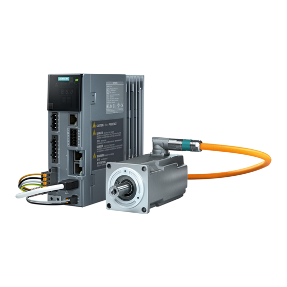
System overview
Integrated
FSC
70
170
195
1,9
20A
Quick Installation Guide
System overview (cont'd)
Line supply 230 V
Fuse and circuit breaker
Line contactor (optional)
Line filter (optional)
External braking resistor (optional)
Power supply 24 V
Ferrite core
Connection the converter
Install the converter so that you comply with local regulations for erecting and installing low voltage
systems.
Notes
Operating displays for converter operation
If, when switching over a function from ON to OFF, an LED or other similar display is not lit or not active;
this does not indicate that the device is switched-off or in a no-current condition.
Converter is grounded (earthed) correctly
Make sure that the shield of the motor cable is properly grounded (earth). Use the shielding clamp
which comes with the cable to mount the cable to the converter's shielding plate.
Safety devices
Install suitable protective equipment between the line supply and converter.
Protection and monitoring equipment
To provide protection against short-circuit, use the overcurrent devices listed in the Technical data (fuses,
circuit breakers etc.).
If the apparent impedance of the line supply at the infeed point is not suitable, so that fuses
do not rupture in the specified time in the case of insulation failure (ground fault, fault to frame), then you
must use additional residual current protective devices RCD (RCCB or MRCD), type B.
To prevent an RCD from unnecessarily tripping as a result of operational leakage currents, the following
preconditions must be fulfilled:
• The neutral point of the line supply is grounded.
• Use an RCCB type B with a response limit current of 300 mA. Connect the RCCB in series with the
overcurrent protective devices.
• Use a separate RCD for each converter.
• The motor cables are shorter than 50 m (164 ft) shielded.
Connections and operator controls on the converter
Depth (mm)
Weight (kg)
170
1.1
170
1.2
195
1.9
Error acknowledge
X124
24V supply voltage -
daisy chain connection
↔ 30 m
X1
Mains supply and
external braking resistor
↔ braking resistor 3 m
X2
Motor connection
↔ 50 m
Shielding plate for shielded
cables (use sheilding clamp)
Cables and connections
Circular connector M12 or M17, 10-pin
MOTION-CONNECT OCC cable
Shielding
X1: Line connection and connection for external braking resistor
Pin
Connection for
L1
Phase L1 line system
Shield clamps
N
Neutral conductor
External braking resistor
SD-memory card (optional)
DCP
Internal braking resistor
Shielding plate
R2
Internal braking resistor
OCC - connecting cable for Motor Holding
R1
External braking resistor
Brake and encoder
Weidmuller: BLF 5.08HC/05/180F SN BK BX, article number 1012670000
Servomotor 1FK2
As daisy chain: BLDF 5.08/05/180F SN BK BX, article number 1000970000
Commissioning using PC
The terminals are spring-type terminals.
Permissible conductor cross-sections for single-core connection or for the connection of flexible cables
with end sleeves:
Control example; SIMATIC S7-1500 PLC
• 0.2 mm
... 2.5 mm
2
2
• AWG: 26 ... 12
X2: Power connections for the motor
Pin
Pin assignment
U
Motor phase U
V
Motor phase V
W
Motor phase W
PE
Protective ground
Weidmuller: BLF 5.08HC/05/180F SN BK BX, article number 1012660000
The terminals are spring-type terminals.
Permissible conductor cross-sections for single-core connection or for the connection of flexible cables
with end sleeves:
• 0.2 mm
2
... 2.5 mm
2
• AWG: 26 ... 12
X100: Siemens IX connector: Encoder connection
Pin
Pin assignment
1
TXP
2
TXN
3
Reserved
4
Reserved
5
Reserved
6
RXP
7
RXN
8
Reserved
9
Reserved
10
Reserved
Siemens IX, article number 6FX2003-0DE01
X107: Motor holding brake
Status LEDs
Pin
Pin assignment
Error display
BR-
B-
BR+
B+
SD card slot
Phoenix 1745894 FMC 1.5 / 2-ST-3.81, article number 1745894
The terminals are spring-type terminals.
X127
Permissible conductor cross-sections: for single-core connection or for flexible cables with end sleeves
Commissioning
(Webserver [Ethernet])
without plastic protection:
↔ 10 m
• 0.25 mm
... 1.5 mm
, AWG: 24 ... 16
2
2
for flexible cables with end sleeves with plastic protection:
• 0.25 mm
... 0.75 mm
, AWG: 24 ... 19
2
2
X130
Connect the wires for the holding brake to the connector X107 also if you are using a motor without holding
Measuring inputs and
brake.
fail-safe digital inputs
X124: 24 VDC control voltage
Pin
Pin assignment
X150 P1
Profinet Port 1
M
0 V
↔ 100 m
M
0 V
X150 P2
L+
24 V
Profinet Port 2
↔ 100 m
L+
24 V
Dinkle: article number A000101686
X100
Encoder connection
The terminals are spring-type terminals.
↔ 50 m
Permissible conductor cross-sections for single-core connection or for the connection of flexible cables
with end sleeves:
X107
Motor holding brake
• 0.2 mm
... 2.5 mm
2
2
↔ 50 m
• AWG: 26 ... 12
X130: Connector for digital inputs
↔Maximum cable lengths
Pin
Pin assignment
L+
24 V supply
DI 0
High-speed DI, measuring input
M
Ground
L+
24 V supply
DI 1
High-speed DI, measuring input
M
Ground
Dinkle: article number A000101686
The terminals are spring-type terminals.
Wires for holding brake
Permissible conductor cross-sections:
• for single-wire connection: 0.2 mm
Wires for motor power
• for flexible cables with end sleeves: 0.25 mm
• for flexible cables with end sleeves with plastic protection: 0.25 mm
SIEMENS IX connector for signal cable
SINAMICS S210 FSA - FSC
Edition 12/17
Explanation
If you are using the internal braking resistor, DCP
and R2 must be jumpered.
If you are using the external braking resistor, remove
the jumper between DCP and R2.
Connect the external braking resistor by means of
terminals DCP and R1
Colour coding for Siemens OCC cables
Brown
Black
Gray
Green-yellow
Explanation
Sending data + / encoder power supply M
Sending data - / encoder power supply M
Receiving data + / encoder power supply P24+
Receiving data + / encoder power supply P24+
Explanation
Voltage for motor holding brake, 0 V (white)
Voltage for motor holding brake, 24 V (black)
Explanation
Power supply for the converter electronics
Pin assignment
Pin
D1 2+
D1 2-
Fail-safe digital inputs
DI 3+
DI 3-
24 V supply
L+
Digital input
DI 4
2
... 1.5 mm
2
, AWG: 24 ... 16
... 1.5 mm
, AWG: 24 ... 16
2
2
... 0.75 mm
, AWG: 24 ... 19
2
2
Advertisement
Table of Contents

Related Manuals for Siemens SINAMICS S210 FSA


Summary of Contents for Siemens SINAMICS S210 FSA
- Page 1 SINAMICS S210 FSA - FSC Quick Installation Guide Edition 12/17 X1: Line connection and connection for external braking resistor Clearance distances System overview (cont'd) Connection for Explanation Phase L1 line system SINAMICS S210 Line supply 230 V Shield clamps Neutral conductor...
- Page 2 Germany The line filter exceeded temperature limits or has non-permissible state External value/signal out of the range © Siemens AG, 2017 Digital/Analog inputs error (or temperature) Application / technology fault Application or technology function has exceeded a limit (position, velocity, torque…)
Need help?
Do you have a question about the SINAMICS S210 FSA and is the answer not in the manual?
Questions and answers