Allen-Bradley E300 User Manual
Electronic overload relay
Hide thumbs
Also See for E300:
- User manual (736 pages) ,
- Quick start instructions (44 pages) ,
- Installation instructions manual (16 pages)

Related Manuals for Allen-Bradley E300


Summary of Contents for Allen-Bradley E300
- Page 1 User Manual Original Instructions E300 Electronic Overload Relay Bulletin Numbers 193, 592...
- Page 2 Important User Information Read this document and the documents listed in the additional resources section about installation, configuration, and operation of this equipment before you install, configure, operate, or maintain this product. Users are required to familiarize themselves with installation and wiring instructions in addition to requirements of all applicable codes, laws, and standards.
-
Page 3: Table Of Contents
Table of Contents Preface Summary of Changes ......... . 11 Access Relay Parameters . - Page 4 Table of Contents Standard Current-based Protection ......25 Ground Fault Current-based Protection..... 26 Voltage- and Power-based Protection.
- Page 5 Table of Contents Network Start Communication Idle Modes ....53 Introduction to Operating Modes ......54 Chapter 4 Operating Modes Overload Operating Modes .
- Page 6 Table of Contents Two-speed Starter (Network) with Feedback ....102 Two-speed Starter (Operator Station) ..... . 104 Two-speed Starter (Operator Station) with Feedback.
- Page 7 Table of Contents Test Trip ..........145 Thermistor (PTC) Protection .
- Page 8 Integration with Logix-based Controllers..... . . 181 Configure an E300 Relay in a Logix Project ....181 Access I/O Data .
- Page 9 Wiring Diagrams E300 Wiring Configurations ........217...
- Page 10 Table of Contents Notes: Rockwell Automation Publication 193-UM015F-EN-P - August 2018...
-
Page 11: Preface
DeviceNet Communications Module setup and configuration page 187 Access Relay Parameters The spreadsheet that is attached to this PDF details the E300 parameters. To access this file, click the Attachments link (the paper clip) and double-click the file. Additional Resources These documents contain additional information concerning related products from Rockwell Automation. - Page 12 Preface Notes: Rockwell Automation Publication 193-UM015F-EN-P - August 2018...
-
Page 13: Module Descriptions
• True RMS current/voltage sensing (50/60 Hz) • Protection for single- and three-phase motors The E300 relay consists of three modules: sensing, control and communications. You have choices in each of the three with additional accessories to tailor the electronic overload for your application’s exact needs. -
Page 14: Control Module
(1) Includes PTC thermistor and external ground fault. Communication Modules • EtherNet/IP • DeviceNet Expansion Digital I/O You can add up to four additional expansion digital modules to the E300 relay expansion bus. • 4 inputs/2 relay outputs • 24V DC • 120V AC •... -
Page 15: Expansion Power Supply
• 24V DC Expansion Operator Station You can add one operator station to the E300 relay expansion bus to be used as a user interface device. The operator stations provide E300 relay status LEDs and function keys for motor control. The operator stations also support CopyCat™, which allows you to upload and download E300 relay configuration parameters. -
Page 16: Overtemperature Protection (Ptc And Rtd)
Thermal Warning The E300 Electronic Overload Relay provides the capability to alert in the event of an impending overload trip. A thermal warning bit is set in the Current Warning Status when the calculated percentage of thermal capacity utilization exceeds the programmed thermal warning level, which has a setting range of 0…100% TCU. -
Page 17: Stall
250 seconds. Jam (Overcurrent) The E300 Electronic Overload Relay can respond quickly to take a motor off-line in the event of a mechanical jam, reducing the potential for damage to the motor and the power transmission components. Trip adjustments include a trip setting that is adjustable from 50…600% FLA and a trip delay time with a range of 0.1…25.0 seconds. -
Page 18: Current Imbalance (Asymmetry)
Power Protection While the motor is powering a load, the E300 sensing module with voltage, current, and ground fault current, also protects the motor based on power. This option monitors and protects for both excessive and low real power (kW), reactive power (kVAR), apparent power (kVA), and power factor for a specific application (such as pump applications). -
Page 19: Voltage, Power, And Energy Monitoring
The Test/Reset button, which is located on the front of the E300 Electronic Overload Relay, allows you to perform the following: • Test — The trip relay contact opens if the E300 Electronic Overload Relay is in an untripped condition and the Test/Reset button is pressed for 2 seconds or longer. -
Page 20: Single/Three-Phase Operation
Straight-through wiring is available in both cases. EtherNet/IP Communications The E300 EtherNet/IP communication module has two RJ45 ports that act as an Ethernet switch to support a star, linear, and ring topology and supports the following: • 2 concurrent Class 1 connections [1 exclusive owner + (1 input only or 1 listen only)] •... -
Page 21: Communication Options
• Trip Snapshot Simplified Wiring The E300 relay provides an easy means to mount to both IEC and NEMA Allen-Bradley® contactors. A contactor coil adapter is available for the 100-C contactor, which allows you to create a functional motor starter with only two control wires. -
Page 22: Control Module
Control Module Figure 2 - Control Module The control module is the heart of the E300 relay and can attach to any sensing module. The control module performs all protection and motor control algorithms and contains the native I/O for the system. The control module has two varieties: •... -
Page 23: Communication Modules
Optional Add-On Modules Optional Expansion I/O The E300 relay lets you add more digital and analog I/O to the system via the E300 relay Expansion Bus if the native I/O count is not sufficient for the application on the base relay. You can add any combination of up to four Digital I/O Expansion Modules that have four inputs (120V AC, 240V AC, or 24V DC) and two relay outputs. -
Page 24: Optional Operator Station
Stop Reset The E300 relay lets you add one operator interface to the Expansion Bus. You can choose between two types of operator stations: Control Station or a Diagnostic Station. Both types of operator stations mount into a standard 22 mm push button knockout, and they provide diagnostic status indicators that allow you to view the status of the E300 relay from the outside of an electrical enclosure. -
Page 25: Optional Expansion Bus Power Supply
The Diagnostic Station requires Control Module firmware v3.000 or higher. Optional Expansion Bus The E300 relay expansion bus provides enough current to operate a system that has (1) Digital Expansion Module and (1) Operator Station. An E300 relay system that Power Supply contains more expansion modules needs supplemental current for the Expansion Bus. -
Page 26: Ground Fault Current-Based Protection
• Thermistor – PTC (49) • Stator Protection – RTD (49) • Bearing Protection – RTD (38) Applications You can use the E300 relay with the following across the line starter applications: • Non-reversing starter • Reversing starter • Wye (Star) / Delta starter •... -
Page 27: Diagnostic Station
The E300 Diagnostic Station allows you to view parameters by using a group menu system or by a linear list. To start the navigation menu, press the key. The menu prompts you to view parameters by groups, parameters in a linear list, or E300 relay system information. Parameter Group Navigation To start the navigation menu, press the key. -
Page 28: Linear List Navigation
Chapter 2 Diagnostic Station Use the keys to select the parameter group to display and press Use the keys to view the parameters that are associated with that group. When viewing a bit enumerated parameter, press to view the description of each bit. -
Page 29: System Info
The E300 Diagnostic Station can display firmware revision information, view the time and date of the E300 relay virtual clock, and edit the time and date of the E300 relay virtual clock. To view E300 relay system information, start the navigation menu by pressing key. -
Page 30: Editing Parameters
To start the navigation menu, press the key. You are prompted to view parameters by groups, parameters in a linear list, or E300 relay system information. Choose the appropriate method and navigate to the parameter to be modified. -
Page 31: Editing A Bit Enumerated Parameter
Programmable Display Display Sequence Sequence The Diagnostic Station of the E300 relay sequentially displays up to seven screens every 5 seconds. • Three-phase current • Three-phase voltage • Total power •... -
Page 32: Stopping The Display Sequence
436) defines, the Diagnostic Station automatically returns to the programmable display sequence. Automatic Trip and Warning When the E300 relay is in a trip or warning state, the E300 Diagnostic Station automatically displays the trip or warning event. Screens Press any of the navigation keys (... -
Page 33: System Operation And Configuration
Ready Mode Ready Mode is a standby mode for the E300 relay in which the relay is ready to help protect an electric motor and no electrical current has been detected. You can modify configuration parameters, update firmware, and issue commands if the appropriate security policies are enabled. -
Page 34: Option Match
System Operation and Configuration Run Mode Run Mode is an active mode for the E300 relay in which the relay is sensing electrical current and is actively protecting an electric motor. Only non-motor protection configuration parameters can be modified if the appropriate security policies are enabled. -
Page 35: Digital I/O Expansion Modules
Option Match feature for the communication module. Operator Station Type (Parameter 224) The E300 relay offers two different types of operator stations. Place the value of the expected operator station into Parameter 224. A value of (0) disables the Option Match feature for the operator station. -
Page 36: Analog I/O Expansion Modules
System Operation and Configuration Module 3 Type (Parameter 227) The E300 relay supports up to four additional Digital I/O expansion modules. This parameter configures the Option Match feature for the Digital I/O expansion module set to Digital Module 3. There are three different types of Digital I/O expansion modules. -
Page 37: Option Match Action (Parameter 233)
• when this policy is disabled, all external message instructions with configuration data return a communication error when the E300 relay is in Ready Mode or Run Mode • allows you to send external message instruction via a communication network to perform a soft device reset when the E300 relay is in Ready Mode Device Reset •... -
Page 38: Output Assignments
• Output Pt02 Assignment (Parameter 204) Output Relay Configuration When assigned as a Normal/General Purpose Relay or Control/Control & Trip Relay, you can configure the E300 relay's output relays to go to a specific safe state when one States of following events occur: •... -
Page 39: Output Relay Protection Fault Modes
Chapter 3 Output Relay Protection Fault Modes When the E300 relay has a trip event, you can configure the E300 output relays to go to a specific state (Open or Closed) or ignore the trip event and continue to operate as normal. -
Page 40: Output Relay Communication Idle Modes
Parameter Fault Name Description • defines the amount of time (s) that the E300 relay remains in the Communication Fault Mode state when a communication fault occurs. 0 = forever Fault Mode Output State Duration • If communication between the E300 relay and a network scanner or control system is not... -
Page 41: Expansion Bus Fault
Mode or a PLC goes into Program Mode Expansion Bus Fault The expansion bus of the E300 relay can be used to expand the I/O capabilities of the device with the addition of digital and analog expansion I/O modules. The Expansion... -
Page 42: Emergency Start
IMPORTANT Activating Emergency Start inhibits overload and blocked start protection. Running in this mode can cause equipment overheating and fire. To enable the Emergency Start feature in the E300 relay, set the Emergency Start Enable (Parameter 216) to Enable. Table 7 - Emergency Start (Parameter 216) -
Page 43: Language
Description User-defined Screen 1 – Parameter 1 • the E300 parameter number to display for the first parameter in user-defined screen 1 User-defined Screen 1 – Parameter 2 • the E300 parameter number to display for the second parameter in user-defined screen 1 User-defined Screen 2 –... -
Page 44: Analog Input Channels
Chapter 3 System Operation and Configuration Analog Input Channels The universal analog inputs can accept the following analog signals: • Current – 4…20 mA – 0…20 mA • Voltage – 0…10V DC – 1…5V DC – 0…5V DC • 2-Wire or 3-Wire RTD Sensors –... - Page 45 System Operation and Configuration Chapter 3 Table 11 - Analog Input Data Format for Voltage Input Type Input Engineering Engineering Raw / Input Value Condition Range Units Units x 10 Proportional 10.50V DC High Limit 10500 1050 32767 17202 10.00V DC High Range 10000 1000...
- Page 46 Low Limit -32768 The performance for the input channels of the E300 Analog I/O Expansion Module is dependent on the filter setting for each channel. The total scan time for the input channels of the module is determined by adding the conversion time for all enabled input channels.
-
Page 47: Analog Output Channel
• Channel 01 is configured for 17 Hz voltage (conversion time = 153 ms). • Channel 02 is configured for 62 Hz current (conversion time = 65 ms). The E300 Analog I/O Expansion Module input channel scan time is 1242 ms (1024+153+65). - Page 48 Low Limit 0.00% The analog output can be used to communicate E300 diagnostic information via an analog signal to distributed control systems, programmable logic controllers, or panel- mounted analog meters. The analog output can represent one of the following E300 diagnostic parameters: •...
-
Page 49: Analog Modules
• defines the E300 relay parameter that Output Channel 00 represents Output Channel 00 Expansion Bus Fault Action • defines the value that Output Channel 00 provides when there is an E300 Expansion Bus fault Output Channel 00 Protection Fault Action •... - Page 50 • defines the value that the E300 Analog I/O Expansion Module Output Channel 00 provides when there is an E300 Output Channel 00 Expansion Bus Fault Action Expansion Bus fault • defines the value that the E300 Analog I/O Expansion Module Output Channel 00 provides when the E300 is in a Output Channel 00 Protection Fault Action tripped state (1) Open circuit detection is always enabled for this input channel.
- Page 51 • defines the value that the E300 Analog I/O Expansion Module Output Channel 00 provides when there is an E300 Output Channel 00 Expansion Bus Fault Action Expansion Bus fault • defines the value that the E300 Analog I/O Expansion Module Output Channel 00 provides when the E300 is in a Output Channel 00 Protection Fault Action tripped state (1) Open circuit detection is always enabled for this input channel.
-
Page 52: Network Start Configuration States
• defines the value that the E300 Analog I/O Expansion Module Output Channel 00 provides when there is an E300 Output Channel 00 Expansion Bus Fault Action Expansion Bus fault • defines the value that the E300 Analog I/O Expansion Module Output Channel 00 provides when the E300 is in a Output Channel 00 Protection Fault Action tripped state (1) Open circuit detection is always enabled for this input channel. -
Page 53: Network Start Communication Fault Modes
Parameter Name Description • defines the amount of time in seconds that the E300 remains in the Network Start Communication Fault Mode state when a communication fault occurs. 0 = forever Fault Mode Output State Duration • if communication between the E300 relay and a network scanner or control system is not restored within the... -
Page 54: Introduction To Operating Modes
The default Operating Mode (Parameter 195) for the E300 relay is Overload (Network) in which the E300 relay operates like a traditional overload relay in which one of the output relays is assigned as a Trip Relay or Control Relay. You can use network commands to control any output relays that are assigned as Normal output relays or Control Relays. -
Page 55: Operating Modes
• Operator Station • Local I/O • Custom The E300 relay is wired as a traditional overload relay with one of the output relays configured as a normally closed trip relay. Figure 7 is a wiring diagram of a non- reversing starter. -
Page 56: Overload (Network)
Motor (1) Contact shown with supply voltage applied. For Control Module firmware v3.000 and higher, you can also wire the E300 relay as a control relay so that the relay that is controlled by the communication network opens when a trip event occurs. -
Page 57: Overload (Operator Station)
Station) operating mode is used when an automation controller uses the start and stop keys of the E300 Operator Station for its motor control logic. You can use network commands to control the control relay or any of the remaining output relays that are assigned as normal output relays. -
Page 58: Overload (Local I/O)
E300 Operator Station. You can use the digital inputs of the E300 for the motor control logic of an automation controller. The automation controller can use network commands to control the control relay or any of the remaining output relays that are assigned as Normal output relays. -
Page 59: Non-Reversing Starter Operating Modes
A normally open control relay controls the Operating Modes contactor coil. When a trip event occurs, the control relay remains open until the E300 receives a trip reset command. There are 15 non-reversing starter-based operating modes to choose from: •... -
Page 60: Non-Reversing Starter (Network) With Feedback
3. Overload Trip must be enabled in TripEnableI (Parameter 183). Wiring Diagram The E300 relay’s Output Relay 0 is wired as a control relay in which the relay is controlled by the communication network and opens when a trip event occurs. - Page 61 Warning in WarningEnableC (Parameter 192) must be enabled. Wiring Diagram The E300 relay’s Output Relay 0 is wired as a control relay in which the relay is controlled by the communication network and opens when a trip event occurs. Figure 12 is a wiring diagram of a non-reversing starter with the contactor auxiliary wired to Input 0 and Output Relay 0 configured as a control relay.
-
Page 62: Non-Reversing Starter (Operator Station)
These keys are momentary push buttons, so the non- reversing starter remains energized when you release the “I” button. The E300 relay issues a trip or warning event if the E300 Operator Station disconnects from the base relay. - Page 63 6. Communication Fault & Idle Override (Parameter 346) must be enabled. 7. Network Fault Override (Parameter 347) must be enabled. Wiring Diagram The E300 relay’s Output Relay 0 is wired as a control relay, and it opens when a trip event occurs. Figure 14 is a wiring diagram of a non-reversing starter with Output Relay 0 configured as a control relay.
-
Page 64: Non-Reversing Starter (Operator Station) With Feedback
Warning in WarningEnableC (Parameter 192) must be enabled. Wiring Diagram The E300 relay’s Output Relay 0 is wired as a control relay in which the relay is controlled by the communication network and opens when a trip event occurs. Figure 16 is a wiring diagram of a non-reversing starter with the contactor auxiliary wired to Input 0 and Output Relay 0 configured as a control relay. -
Page 65: Non-Reversing Starter (Local I/O) - Two-Wire Control
Input 0 is a maintained value, so the non-reversing starter remains energized when Input 0 is active. The reset button of the E300 Operator Station is enabled for this operating mode. Rockwell Automation Publication 193-UM015F-EN-P - August 2018... - Page 66 5. Network Fault Override (Parameter 347) must be enabled. Wiring Diagram The E300 relay’s Output Relay 0 is wired as a control relay in which the relay is controlled by the state of Input 0 and opens when a trip event occurs.
-
Page 67: With Feedback
6. Network Fault Override (Parameter 347) must be enabled. Wiring Diagram The E300 relay’s Output Relay 0 is wired as a control relay in which the relay is controlled by the state if Input 1 and opens when a trip event occurs. -
Page 68: Non-Reversing Starter (Local I/O) - Three-Wire Control
Output Relay 0. Both Input 0 and Input 1 are momentary values, so the non- reversing starter only energizes if Input 0 is active and Input 1 is momentarily active. The reset button of the E300 Operator Station is enabled for this operating mode. Rockwell Automation Publication 193-UM015F-EN-P - August 2018... - Page 69 5. Network Fault Override (Parameter 347) must be enabled. Wiring Diagram The E300 relay’s Output Relay 0 is wired as a control relay in which the relay is energized when Input 0 is active and Input 1 is momentarily active. Output Relay 0 de- energizes when Input 0 is momentarily de-active or when a trip event occurs.
-
Page 70: Non-Reversing Starter (Local I/O)
7. Network Fault Override (Parameter 347) must be enabled. Wiring Diagram The E300 relay’s Output Relay 0 is wired as a control relay in which the relay is controlled by the state if Input 1 and opens when a trip event occurs. -
Page 71: Non-Reversing Starter (Network & Operator Station)
Remote” button on the E300 Operator Station. The LED above “Local/Remote” button illuminates yellow in Local control mode and red in Remote control mode. The E300 relay issues a trip or warning event if the E300 Operator Station disconnects from the base relay. - Page 72 7. Network Fault Override (Parameter 347) must be enabled. Wiring Diagram The E300 relay’s Output Relay 0 is wired as a control relay in which the relay is controlled by the communication network and opens when a trip event occurs.
-
Page 73: With Feedback
Feedback Timeout (Parameter 213), then the E300 relay issues a trip or warning event. The E300 relay issues a trip or warning event if the E300 Operator Station disconnects from the base relay. -
Page 74: Non-Reversing Starter (Network & Local I/O)
8. Network Fault Override (Parameter 347) must be enabled. Wiring Diagram The E300 relay’s Output Relay 0 is wired as a control relay in which the relay is controlled by the communication network and opens when a trip event occurs. - Page 75 5. Network Fault Override (Parameter 347) must be enabled. Wiring Diagram The E300 relay’s Output Relay 0 is wired as a control relay in which the relay is controlled by the communication network and opens when a trip event occurs.
-
Page 76: Non-Reversing Starter (Network & Local I/O) With Feedback
Feedback Timeout (Parameter 213), then the E300 relay issues a trip or warning event. The reset button of the E300 Operator Station is enabled for this operating mode. IMPORTANT The Non-reversing Starter (Network &... - Page 77 7. Network Fault Override (Parameter 347) must be enabled. Wiring Diagram The E300 relay’s Output Relay 0 is wired as a control relay in which the relay is controlled by the communication network and opens when a trip event occurs.
-
Page 78: Three-Wire Control
Input 3 is used to select between Local and Remote control mode. Activate Input 3 to select Remote control mode. De-activate Input 3 to select Local control mode. The reset button of the E300 Operator Station is enabled for this operating mode. IMPORTANT The Non-reversing Starter (Network &... -
Page 79: Non-Reversing Starter (Network & Local I/O) With Feedback
6. Network Fault Override (Parameter 347) must be enabled. Wiring Diagram The E300 relay’s Output Relay 0 is wired as a control relay in which the relay is controlled by the communication network and opens when a trip event occurs. - Page 80 7. Network Fault Override (Parameter 347) must be enabled. Wiring Diagram The E300 relay’s Output Relay 0 is wired as a control relay in which the relay is controlled by the communication network and opens when a trip event occurs.
-
Page 81: Non-Reversing Starter (Custom)
3. Overload Trip must be enabled in TripEnableI (Parameter 183). Wiring Diagram The E300 relay can also be wired as a control relay so that the relay that is controlled by the communication network opens when a trip event occurs. -
Page 82: Reversing Starter Operating Modes
Two normally open control relays control the Modes forward and reverse contactor coils. When a trip event occurs, both control relays remain open until the E300 receives a trip reset command. There are 11 reversing starter-based operating modes to choose from: • Network •... -
Page 83: Reversing Starter (Network) With Feedback
Chapter 4 Wiring Diagram The E300 relay’s Output Relay 0 is wired as a control relay to the forward contactor and Output Relay 1 is wired as a control relay to the reversing contactor in which both relays are controlled by the communication network and open when a trip event occurs. - Page 84 Warning in WarningEnableC (Parameter 192) must be enabled. Wiring Diagram The E300 relay’s Output Relay 0 is wired as a control relay to the forward contactor and Output Relay 1 is wired as a control relay to the reversing contactor in which both relays are controlled by the communication network and open when a trip event occurs.
-
Page 85: Reversing Starter (Operator Station)
Reversing Starter (Operator Station) The E300 relay’s Operating Mode Reversing Starter (Operating Station) (Parameter 195 = 29) uses the E300 Operator Station’s “I” key to control Output Relay 0, which controls the forward contactor coil. The “II” key controls Output Relay 1, which controls the reversing contactor coil. - Page 86 8. Network Fault Override (Parameter 347) must be enabled. Wiring Diagram The E300 relay’s Output Relay 0 is wired as a control relay to the forward contactor, and Output Relay 1 is wired as a control relay to the reversing contactor. Both relays open when a trip event occurs.
-
Page 87: Reversing Starter (Operator Station) With Feedback
The E300 relay’s Operating Mode Reversing Starter (Operator Station) with Feedback (Parameter 195 = 30) uses the E300 Operator Station’s “I” and “0” keys to control Relay 0, which controls the contactor coil. These keys are momentary push buttons, so the reversing starter remains energized when you release the “I”... - Page 88 Warning in WarningEnableC (Parameter 192) must be enabled. Wiring Diagram The E300 relay’s Output Relay 0 is wired as a control relay to the forward contactor and Output Relay 1 is wired as a control relay to the reversing contactor. Both relays open when a trip event occurs.
-
Page 89: Reversing Starter (Local I/O) - Two-Wire Control
The Reversing Starter (Local I/O) – Two-wire Control operating mode uses the signal from Input 0 or Input 1 to control the starter. When an E300 relay powers up, the starter energizes if either Input 0 or Input 1 is active. - Page 90 6. Network Fault Override (Parameter 347) must be enabled. Wiring Diagram The E300 relay’s Output Relay 0 is wired as a control relay to the forward contactor and Output Relay 1 is wired as a control relay to the reversing contactor. Both relays open when a trip event occurs.
-
Page 91: Two-Wire Control With Feedback
The Reversing Starter (Local I/O) – Two-wire Control operating mode uses the signal from Input 0 or Input 1 to control the starter. When an E300 relay powers up, the starter energizes if either Input 0 or Input 1 is active. -
Page 92: Reversing Starter (Local I/O) - Three-Wire Control
Relay 1 Run Reverse DeviceLogix Program The DeviceLogix program is automatically loaded and enabled in the E300 relay on power-up or when Operating Mode (Parameter 195) is set to a value of 41. Timing Diagram Figure 47 - Reversing Starter (Operator Station) with Feedback Timing Diagram... - Page 93 Input 2 must be momentarily de-active before changing to another direction. InterlockDelay (Parameter 215) defines the minimum time delay when switching direction. The reset button of the E300 Operator Station is enabled for this operating mode. Rules 1. Available for Control Module firmware v5.000 and higher.
-
Page 94: Reversing Starter (Network & Operator Station)
(Parameters 569 – 573) described in Chapter In Local control mode, the E300 Operator Station’s “I” key is used to control Output Relay 0, which controls the forward contactor coil. The “II” key controls Output Relay 1, which controls the reversing contactor coil. The “0” key is used to de-energize Output Relay 0 and Output Relay 1. - Page 95 8. Network Fault Override (Parameter 347) must be enabled. Wiring Diagram The E300 relay’s Output Relay 0 and Output Relay 1 are wired as a control relays in which the relay is controlled by the communication network or E300 Operator Station, and both output relays open when a trip event occurs.
-
Page 96: Reversing Starter (Network & Local I/O) - Two-Wire Control
7. Network Fault Override (Parameter 347) must be enabled. Wiring Diagram The E300 relay’s Output Relay 0 and Output Relay 1 are wired as a control relays in which the relay is controlled by the communication network or Input 0 & Input 1. -
Page 97: Reversing Starter (Network & Local I/O) - Three-Wire Control
Relay 1 Run Reverse DeviceLogix Program The DeviceLogix program is automatically loaded and enabled in the E300 relay on power-up or when Operating Mode (Parameter 195) is set to a value of 20. Timing Diagram Figure 52 - Reversing Starter (Network & Local I/O) – Two-wire Control Timing Diagram... - Page 98 7. Network Fault Override (Parameter 347) must be enabled. Wiring Diagram The E300 relay’s Output Relay 0 and Output Relay 1 are wired as a control relays in which the relay is controlled by the communication network or Input 0, Input 1, and Input 2.
-
Page 99: Reversing Starter (Custom)
Relay 1 Run Reverse DeviceLogix Program The DeviceLogix program is automatically loaded and enabled in the E300 relay on power-up or when Operating Mode (Parameter 195) is set to a value of 21. Reversing Starter (Custom) The E300 relay’s Operating Mode Reversing Starter (Custom) (Parameter 195 = 51) operates as a reversing starter with two output relays that are assigned as normally open control relays. -
Page 100: Two-Speed Starter Operating Modes
Two normally open control relays control the Modes high-speed and low-speed contactor coils. When a trip event occurs, both control relays remain open until the E300 receives a trip reset command. There are 11 two- speed starter-based operating modes to choose from: • Network •... -
Page 101: Two-Speed Starter (Network)
4. Overload Trip must be enabled in TripEnableI (Parameter 183). Wiring Diagram The E300 relay’s Output Relay 0 is wired as a control relay to the high-speed contactor and Output Relay 1 is wired as a control relay to the low-speed contactor. In this configuration, both relays are controlled by the communication network and open when a trip event occurs. -
Page 102: Two-Speed Starter (Network) With Feedback
E300 relay issues a trip or warning event. InterlockDelay (Parameter 215) defines the minimum time delay when switching direction. The reset button of the E300 Operator Station is enabled for this operating mode. IMPORTANT The Two-speed Starter (Network) operating mode uses the value in network tag LogicDefinedPt00Data or LogicDefinedPt01Data to control the starter. - Page 103 Warning in WarningEnableC (Parameter 192) must be enabled. Wiring Diagram The E300 relay’s Output Relay 0 is wired as a control relay to the high-speed contactor and Output Relay 1 is wired as a control relay to the low-speed contactor. In this configuration, both relays are controlled by the communication network and open when a trip event occurs.
-
Page 104: Two-Speed Starter (Operator Station)
The E300 relay’s Operating Mode Two Speed Starter (Operating Station) (Parameter 195 = 33) uses the E300 Operator Station’s “I” key to control Output Relay 0, which controls the high-speed contactor coil. The “II” key controls Output Relay 1, which controls the low-speed contactor coil. - Page 105 8. Network Fault Override (Parameter 347) must be enabled. Wiring Diagram The E300 relay’s Output Relay 0 is wired as a control relay to the high-speed contactor, and Output Relay 1 is wired as a control relay to the low-speed contactor. Both relays open when a trip event occurs.
-
Page 106: Two-Speed Starter (Operator Station) With Feedback
The E300 relay’s Operating Mode Two Speed Starter (Operator Station) with Feedback (Parameter 195 = 34) uses the E300 Operator Station’s “I” and “0” keys to control Relay 0, which controls the contactor coil. These keys are momentary push buttons, so the two-speed starter remains energized when you release the “I”... - Page 107 Warning in WarningEnableC (Parameter 192) must be enabled. Wiring Diagram The E300 relay’s Output Relay 0 is wired as a control relay to the high-speed contactor and Output Relay 1 is wired as a control relay to the low-speed contactor. Both relays open when a trip event occurs.
-
Page 108: Two-Speed Starter (Local I/O) - Two-Wire Control
The Two-speed Starter (Local I/O) – Two-wire Control operating mode uses the signal from Input 0 or Input 1 to control the starter. When an E300 relay powers up, the starter energizes if either Input 0 or Input 1 is active. - Page 109 6. Network Fault Override (Parameter 347) must be enabled. Wiring Diagram The E300 relay’s Output Relay 0 is wired as a control relay to the high-speed contactor and Output Relay 1 is wired as a control relay to the low-speed contactor. Both relays open when a trip event occurs.
-
Page 110: Two-Wire Control With Feedback
The Two-speed Starter (Local I/O) – Two-wire Control operating mode uses the signal from Input 0 or Input 1 to control the starter. When an E300 relay powers up, the starter energizes if either Input 0 or Input 1 is active. -
Page 111: Two-Speed Starter (Local I/O) - Three-Wire Control
Trip Two-speed Starter (Local I/O) – Three-wire Control The E300 relay’s Operating Mode Two Speed Starter (Local I/O) – Three Wire Control (Parameter 195 = 48) uses a normally open momentary push button in Input 0 to energize Output Relay 0, which controls the high-speed contactor coil. A normally open momentary push button in Input 1 is used to energize Output Relay 1, which controls the low-speed contactor coil. - Page 112 Input 0 or Input 1 is momentarily active. InterlockDelay (Parameter 215) defines the minimum time delay when switching direction. The reset button of the E300 Operator Station is enabled for this operating mode. Rules 1. Available for Control Module firmware v5.000 and higher.
-
Page 113: Two-Speed Starter (Network & Operator Station)
Network Communication Idle parameters (Parameters 569 – 573) described in Chapter In Local control mode, the E300 Operator Station’s “I” key is used to control Output Relay 0, which controls the high-speed contactor coil. The “II” key controls Output Relay 1, which controls the low-speed contactor coil. The “0” key is used to de-energize Output Relay 0 and Output Relay 1. - Page 114 8. Network Fault Override (Parameter 347) must be enabled. Wiring Diagram The E300 relay’s Output Relay 0 and Output Relay 1 are wired as a control relays in which the relay is controlled by the communication network or E300 Operator Station, and both output relays open when a trip event occurs.
-
Page 115: Two-Wire Control
Remote control mode. De-activate Input 3 to select Local control mode. InterlockDelay (Parameter 215) defines the minimum time delay when switching direction. The reset button of the E300 Operator Station is enabled for this operating mode. IMPORTANT The Two-speed Starter (Network & Operator Station) operating mode uses the value in network tag LogicDefinedPt00Data or LogicDefinedPt01Data to control the starter. - Page 116 7. Network Fault Override (Parameter 347) must be enabled. Wiring Diagram The E300 relay’s Output Relay 0 and Output Relay 1 are wired as a control relays in which the relay is controlled by the communication network or Input 0 & Input 1.
-
Page 117: Three-Wire Control
Remote control mode. De-activate Input 3 to select Local control mode. InterlockDelay (Parameter 215) defines the minimum time delay when switching direction. The reset button of the E300 Operator Station is enabled for this operating mode. Rockwell Automation Publication 193-UM015F-EN-P - August 2018... - Page 118 7. Network Fault Override (Parameter 347) must be enabled. Wiring Diagram The E300 relay’s Output Relay 0 and Output Relay 1 are wired as a control relays in which the relay is controlled by the communication network or Input 0, Input 1, and Input 2.
-
Page 119: Monitor Operating Mode
Monitor Operating Mode The E300 relay’s monitor-based operating mode allows you to disable all protection features of the E300 relay. You can use the E300 relay as a monitoring device to report current, voltage, power, and energy information. There is one monitor based operating mode – Custom. -
Page 120: Monitor (Custom)
Monitor (Custom) The E300 relay’s Operating Mode Monitor (Custom) (Parameter 195 = 54) allows you to use the E300 relay as a monitoring device. No configuration rules apply in this operating mode if all motor protection features are disabled. Rules 1. -
Page 121: Protective Trip And Warning Functions
• Power-based • Control-based • Analog-based This chapter explains the trip and warning protection features of the E300 relay and the associated configuration parameters. Current Protection The E300 relay digitally monitors the electrical current that is consumed by an electric motor. -
Page 122: Current Warning
• Any relay outputs configured as warning alarm close Overload Protection The E300 relay provides overload protection through true RMS current measurements of the individual phase currents of the connected motor. Based on the highest current measured, the programmed FLA Setting, and Trip Class, a thermal model that simulates the actual heating of the motor is calculated. - Page 123 5…30. Enter the application trip class into Trip Class (Parameter 172). Select the reset mode for the E300 relay after an overload or thermistor (PTC) trip. If an overload trip occurs and automatic reset mode is selected, the E300 relay automatically resets when the value stored...
- Page 124 Chapter 5 Protective Trip and Warning Functions Trip Curves The following figures illustrate the E300 relay’s time-current characteristics for trip classes 5, 10, 20, and 30. Figure 76 - Time-Current Characteristics for Trip Classes 5, 10, 20, and 30 Trip Class 5...
-
Page 125: Phase Loss Protection
The phase loss inhibit timer starts after the maximum phase of load current transitions from 0 A to 30% of the minimum FLA setting of the device. The E300 relay does not begin monitoring for a phase loss condition until the Phase Loss Inhibit Time expires. -
Page 126: Ground Fault Current Protection
The E300 relay provides core-balanced ground fault current detection capability, with the option of enabling Ground Fault Trip, Ground Fault Warning, or both. The ground fault detection method and range depends upon the catalog number of the E300 Sensing Module and Control Module ordered. -
Page 127: Stall Protection
Define the time period a ground fault condition must be present before a trip occurs and is adjustable Ground Fault Trip Delay from 0.0…25.0 s. Ground Fault Trip Level (Parameter 244) allows you to define the ground fault current in which the E300 relay trips and is adjustable from: • 0.500…5.00 A (Internal) •... -
Page 128: Jam Protection
Define the time period a jam condition must be present before a trip occurs. It is adjustable from Jam Trip Delay 0.1…25.0 s. Define the current at which the E300 relay trips on a jam. It is user-adjustable from 50…600% of the FLA Setting (Parameter 171). IMPORTANT... -
Page 129: Current Imbalance Protection
The Underload Inhibit Timer starts after the maximum phase of load current transitions from 0 A to 30% Underload Trip Level of the minimum fla SETTING of the device. The E300 relay does not begin monitoring for an underload condition until the Underload Inhibit Time expires. -
Page 130: Line Undercurrent Protection
L2 Under Current Trip Delay adjustable from 0.1…25.0 seconds. L3 Under Current Trip Delay Define the current at which the E300 relay trips on a L1 Under Current. It is user-adjustable from 10…100% of the FLA Setting (Parameter 171). IMPORTANT... -
Page 131: Line Loss Protection
Chapter 5 Parameter Name Parameter Number Description Define the current at which the E300 relay trips on a L1 Over Current. It is user-adjustable from 10…100% of the FLA Setting (Parameter 171). L1 Over Current Trip Level IMPORTANT L2 Over Current Trip Level... -
Page 132: Voltage Trip
Voltage Trip Status (Parameter 5) and Voltage Warning Status (Parameter 11) are used to view the status of the respective voltage-based protective trip and warning functions. Voltage Trip The E300 relay trips with a voltage indication if: • No trip currently exists • A voltage trip is enabled •... -
Page 133: Voltage Warning
This can damage to an electric motor over an extended period of time. The E300 relay can monitor for this condition with its Under Voltage Trip and Warning function to detect for low voltage levels to minimize motor damage and loss of production. -
Page 134: Overvoltage Protection
Over Voltage Trip Level IMPORTANT The Over Voltage Inhibit Time starts after a phase voltage transitions from 0V to 20V L-L. The E300 relay does not begin monitoring for an over voltage condition until the Over Voltage Inhibit Time expires. -
Page 135: Phase Rotation Protection
IMPORTANT Phase Rotation Trip Type The Phase Rotation Inhibit Time starts after a phase voltage transitions from 0V to 20V L-L. The E300 relay does not begin monitoring for a phase rotation mismatch condition until the Phase Rotation Inhibit Time expires. -
Page 136: Power Protection
IMPORTANT Under Frequency Trip Level The Under Frequency Inhibit Time starts after a phase voltage transitions from 0V to 20V L-L. The E300 relay does not begin monitoring for an under frequency condition until the Under Frequency Inhibit Time expires. -
Page 137: Power Trip
Power Trip Status (Parameter 6) and Power Warning Status (Parameter 12) are used to view the status of the respective power-based protective trip and warning functions. Power Trip The E300 relay trips with power indication if: • No trip currently exists • A power trip is enabled •... -
Page 138: Power Warning
• Any relay outputs configured as a Warning Alarm close Real Power (kW) Protection The E300 relay has the capability to help protect against real power (kW) for specific applications that require the monitoring of both voltage and current. You can help protect or issue a warning if the real power (kW) consumption of an electric motor is either too high or too low. -
Page 139: Reactive Power (Kvar) Protection
The Under kW Inhibit Time starts after a phase voltage transitions from 0V to 20V L-L and a phase of load current transitions from 0 A to 30% of the minimum FLA setting of the device. The E300 relay does not begin monitoring for an under real power (kW) condition until the Under kW Inhibit Time expires. - Page 140 The Under kVAR Generated Inhibit Time starts after a phase voltage transitions from 0V to 20V L-L and a phase of load current transitions from 0 A to 30% of the minimum FLA setting of the device. The E300 relay does not begin monitoring for an under reactive power (kVAR) generated condition until the Under kVAR Generated Inhibit Time expires.
-
Page 141: Apparent Power (Kva) Protection
The Over kVAR Generated Inhibit Time starts after a phase voltage transitions from 0V to 20V L-L and a phase of load current transitions from 0 A to 30% of the minimum FLA setting of the device. The E300 relay does not begin monitoring for an over reactive power (kVAR) generated condition until the Over kVAR Generated Inhibit Time expires. -
Page 142: Power Factor Protection
The Over kVA Inhibit Time starts after a phase voltage transitions from 0V to 20V L-L and a phase of load current transitions from 0 A to 30% of the minimum FLA setting of the device. The E300 relay does not begin monitoring for an over apparent power (kVA) condition until the Over kVA Inhibit Time expires. - Page 143 Chapter 5 Parameter Name Parameter Number Description Define the power factor leading at which the E300 relay trips on an under power factor leading. It is user-adjustable from 0…2,000,000 kW. IMPORTANT Under Power Factor Leading Trip Level The Under Power Factor Leading Inhibit Time starts after a phase voltage transitions from 0V to 20V L-L and a phase of load current transitions from 0 A to 30% of the minimum FLA setting of the device.
-
Page 144: Control Protection
Chapter 5 Protective Trip and Warning Functions Control Protection The E300 relay provides a number of control-based protection functions including: • Test Trip • Operator Station Trip • Remote Trip • Start Inhibit • Preventive Maintenance • Configuration Trip • Option Match Trip/Warning •... -
Page 145: Test Trip
Chapter 5 Test Trip The E300 relay provides the capability to put the overload relay into a Test Trip state. You can implement this feature when commissioning a motor control circuit to verify the response of the E300 relay, its associated Expansion I/O modules, and the networked automation system. -
Page 146: Remote Trip
This protective function allows you to limit the number of starts in a given time period and limit the operating hours for an electric motor. A start is defined as the E300 relay sensing a transition in current from 0 A to 30% of the minimum FLA rating of the device. -
Page 147: Hardware Fault
The E300 relay provides the capability to put the overload relay into a Test Mode Trip state if motor control center enclosure is in a test position, and the E300 relay detects motor current and/or voltage is present. -
Page 148: Analog Protection
Protective Trip and Warning Functions Analog Protection The E300 relay’s Analog I/O Expansion Modules scan up to three analog signals per module. This information can be used to trigger an over analog level Trip or Warning. The analog-based protection features can be used with the following analog applications: •... -
Page 149: Analog Warning
• Any relay outputs configured as a Warning Alarm close Analog Module The E300 supports as many as 4 analog modules. Analog I/O Expansion Module scans up to three analog signals. An over level trip or warning can be configured for each input channel. - Page 150 Analog Module 2 – Channel 01 Trip Level Analog Module 2 – Channel 02 Trip Level Define the magnitude of the analog signal in which the E300 relay trips on a level trip. It is user-adjustable from -32768…+32767. Analog Module 3 – Channel 00 Trip Level Analog Module 3 –...
-
Page 151: Trip Reset
• Clear command Trip Reset Trip Reset (Parameter 163) allows you to reset an E300 relay when it is in a tripped state. Trip Reset has the same functionality as pressing the blue reset button on E300 communication module and using the Trip Reset bit in the consumed output assemblies of a communication network. - Page 152 Chapter 6 Commands Parameter Name Default Units Parameter Name Default Units Parameter Name Default Units Value Value Value WarnHistoryMaskA 0x0FFF OutPt01ComFltVal Open InAnMod1Ch00Type Disable FLASetting 0.50 Amps OutPt01ComIdlAct Goto Value InAMod1Ch0Format Eng Units TripClass OutPt01ComIdlVal Open InAMod1C0TmpUnit Degrees C OLPTCResetMode Automatic OutPt02PrFltAct Goto Value...
- Page 153 Commands Chapter 6 Parameter Name Default Units Parameter Name Default Units Parameter Name Default Units Value Value Value AnalogMod2Type Ignore PhaseRotTripType InAMod2C1WarnLvl AnalogMod3Type Ignore VIBInhibitTime Seconds InAnMod2Ch02Type Disable AnalogMod4Type Ignore VIBTripDelay Seconds InAMod2Ch2Format Eng Units MismatchAction 0x0000 VIBTripLevel InAMod2C2TmpUnit Degrees C PLInhibitTime Seconds VIBWarningLevel...
- Page 154 Chapter 6 Commands Parameter Name Default Units Parameter Name Default Units Parameter Name Default Units Value Value Value L3OCWarningLevel UPFLagWarnLevel InAMod4C0OpCktSt Upscale LineLossInhTime Seconds OPFLagInhibTime Seconds InAnMod4Ch0RTDEn 3-Wire L1LossTripDelay Seconds OPFLagTripDelay Seconds InAMod4C0TripDly Seconds L2LossTripDelay Seconds OPFLagTripLevel InAMod4C0TripLvl L3LossTripDelay Seconds OPFLagWarnLevel InAMod4C0WarnLvl Datalink0...
-
Page 155: Clear Command
Commands Chapter 6 Clear Command Clear Command (Parameter 165) allows you to clear historical logs, operating statistics, and energy data within the nonvolatile memory of the E300 relay. Table 28 - Clear Command Functions Function Name Parameter Name Parameter No. Description... - Page 156 Chapter 6 Commands Function Name Parameter Name Parameter No. Description % Thermal Capacity Utilized Operating Time Starts Counter kWh x 10 kWh x 10 kWh x 10 kWh x 10 kWh x 10 kVARh Consumed x 10 kVARh Consumed x 10 kVARh Consumed x 10 kVARh Consumed x 10 kVARh Consumed x 10...
-
Page 157: Metering And Diagnostics
• reports the calculated percent thermal capacity utilization of the motor that is being monitored (%TCU) • when the percent thermal capacity utilization equals 100%, the E300 relay issues an overload trip • overload Time to Trip indicates the estimated time remaining before an overload trip occurs when the... - Page 158 • reports the state of the digital inputs on the E300 relay Digital Expansion Modules Output Status • reports the state of the relay outputs on the E300 relay Control Module and Digital Expansion Modules Operator Station Status • reports the state of the E300 relay Operator Station input buttons and output LEDs •...
-
Page 159: Current Monitor
Table 31 - Voltage Monitor Parameters Parameter Name Parameter No. Description • reports the voltage in volts in reference to the T1 and T2 power terminals of the E300 relay Sensing L1-L2 Voltage Module • reports the voltage in volts in reference to the T2 and T3 power terminals of the E300 relay Sensing... -
Page 160: Power Monitor
Parameter No. Description L2-N Voltage • reports the voltage in volts in reference to the T2 power terminal of the E300 relay Sensing Module L3-N Voltage • reports the voltage in volts in reference to the T3 power terminal of the E300 relay Sensing Module •... -
Page 161: Energy Monitor
– Total Power Factor = (L1 Power Factor + L2 Power Factor) / 2 Energy Monitor The E300 relay’s energy monitor diagnostics provides information on the electrical energy the load is consuming. The energy diagnostics include kWh, kVARh, kVAh, kW Demand, kVAR Demand, and kVA Demand. - Page 162 Chapter 7 Metering and Diagnostics Parameter Name Parameter No. Description • reports a component of total real energy (kWh) kWh 10 • multiply this value by 10 and add to the other kWh parameters – represents 000,000,000,000. XXX kWh • reports a component of total reactive energy consumed (kVARh) kVARh Consumed 10 •...
-
Page 163: Analog Monitor
• reports the status of Analog Module 4 Trip / Warning History The E300 relay provides a trip and warning history in which the last five trips and last five warnings are recorded into nonvolatile storage. A mask is available to limit which trip and warning events are logged to the history’s memory. - Page 164 Chapter 7 Metering and Diagnostics Table 35 - Trip History Codes Trip History Code Description No Fault Conditions Detected Motor current overload condition Phase current Loss is detected in one of the motor phases Power conductor or motor winding is shorting to ground Motor has not reached full speed by the end of Stall Enable Time Motor current has exceeded the programmed jam trip level Motor current has fallen below normal operating levels...
- Page 165 Metering and Diagnostics Chapter 7 Trip History Code Description Maximum starts per hour exceeded Hardware configuration fault. Check for shorts on input terminal DeviceLogix Feedback Timeout Trip was detected Control Module CAN0 initialization failure Control Module CAN0 bus failure Control Module CAN1 initialization failure Control Module CAN1 bus failure Control Module ADC0 failure Control Module detected too many CRC errors...
-
Page 166: Trip History Parameters
• reports the fifth most recent trip event Trip History Mask You can decide which trip events are recorded into the E300 relay’ s trip history by using the Trip History Masks Current Trip History Mask • allows you to select which current-based trip events are recorded in the trip history Voltage Trip History Mask •... - Page 167 Metering and Diagnostics Chapter 7 Warning History Code Description Over Reactive Power Generated (-kVAR) condition detected Total Apparent Power (kVA) is below warning level Total Apparent Power (kVA) exceeded warning level Under Total Power Factor Lagging (-PF) condition detected Over Total Power Factor Lagging (-PF) condition detected Under Total Power Factor Leading (+PF) condition detected Over Total Power Factor Leading (+PF) condition detected PTC input indicates that the motor stator windings overheated...
-
Page 168: Warning History Parameters
Table 39 - Trip Snapshot Parameters Parameter Name Parameter No. Description • reports the voltage in volts in reference to the T1 and T2 power terminals of the E300 relay Sensing Module at the time of Trip Snapshot L1-L2 Voltage the most recent trip event •... -
Page 169: Devicelogix™ Functionality
(missing I/O connection) or communication idle (network scanner or programmable logic controller is not in Run mode) condition exists – If DeviceLogix functionality is enabled but Communication Fault & Idle Override is disabled, the operation of the E300 output relays is controlled by the Communication Fault Mode and Communication Idle Mode parameters if a communication fault or communication idle condition occurs. -
Page 170: Devicelogix Programming
Boolean operations with any of the available I/O. The inputs and outputs used to interface with the logic can come from the network or from the E300 digital inputs and output relays. There are many reasons to use the DeviceLogix functionality, but some of the most common are listed below: •... -
Page 171: Ethernet/Ip Communication
Chapter EtherNet/IP Communication This chapter provides the necessary instructions to successfully connect the E300™ Electronic Overload Relay EtherNet/IP Communication Module (Catalog Number 193-ECM-ETR) to an Ethernet network and configure it to communicate to an EtherNet/IP scanner such as an Allen-Bradley Logix controller. -
Page 172: Set The Ip Address
• DNS addressing • Duplicate IP address detection Set the IP Address The E300 relay EtherNet/IP Communication Module ships with DHCP enabled. You can set the network Internet Protocol (IP) address by using: • The EtherNet/IP node address selection switches •... -
Page 173: Assign Network Parameters Via The Bootp/ Dhcp Utility
IMPORTANT Before starting the BOOTP/DHCP utility, make sure you have the hardware MAC ID of the module, which is printed on the front of the E300 relay EtherNet/IP Communication Module. The MAC ID has a format similar to: 00-0b-db-14-55-35. This utility recognizes DHCP-enabled devices and provides an interface to configure a static IP address for each device. - Page 174 BOOTP or DHCP requests. 5. Double-click the MAC address of the module to be configured. NOTE: The MAC address is printed underneath the sliding front cover of the E300 relay EtherNet/IP Communication Module. The format of the hardware address resembles: 00-0b-db-14-55-35 The New Entry window appears with the module's Ethernet Address (MAC).
-
Page 175: Mac Scanner Software
Administration Mode. To do this, set the rotary dials that are located underneath the front cover of the E300 relay EtherNet/IP Communication Module to 000 and cycle power. The device then goes online with the IP Address used at the time of the previous startup. -
Page 176: Permanently Enable The Web Server
If you forget or misplace the password for user name Administrator, you can restore the password to the factory default value by turning the rotary dials on the E300 EtherNet/IP Communication Module to 8-8-8 and cycling power. This resets all EtherNet/IP communication settings and E300 configuration parameters back to the factory default values. -
Page 177: View And Configure Parameters Via The Web Server
The web server in the E300 relay EtherNet/IP Communication Module, when enabled, can view and configure parameters for the E300 relay. You can use the web Parameters via the Web interface to edit parameters for E300 relay if it is not being scanned by an EtherNet/IP Server scanner. - Page 178 3. To increase the update rate of the data being viewed, enter a faster update time in the refresh rate box shown below: 4. E300 relay EtherNet/IP Communication Module web page displays up to 17 parameters per web page. If more than 17 parameters exist for a parameter group, use the navigation arrows to display the other parameters.
-
Page 179: Edit Parameters
2. Click the down arrow on the pull-down boxes to adjust fixed values and/or enter numerical values in the fields without an arrow to adjust the values. 3. Click Apply once all parameter edits have been completed. The E300 relay EtherNet/IP Communication Module downloads the new parameter values to the device. -
Page 180: Back Up/Restore Parameters
EtherNet/IP Communication Back up/Restore Parameters With an E300 Series B Control Module and v7.xxx firmware installed, you have the option to back up or restore the device configuration parameters through the E300 web server interface. (Note: the backup/restore feature does not include any administrative parameters or DeviceLogix programming). -
Page 181: Integration With Logix-Based Controllers
1756-PM012. Configure an E300 Relay in a Logix Project Use the Studio 5000 Logix Designer application to configure an E300 relay in a Logix project. Download and install the Add-on Profile. Download firmware, associated files (such as AOP, DTM, and EDS), and access product release notes from only the... -
Page 182: Access I/O Data
Identify and fix the reason for the communication error and press Upload again, or press Cancel to remove any module definition changes. If the upload is not successful due to an E300 configuration trip, a display appears indicating that the profile is using its existing settings. Click OK to continue. Read parameters 38 and 39 from the E300 relay to determine the reason for the configuration trip. -
Page 183: E-Mail/Text
EtherNet/IP Communication Chapter 9 To control the output relays or issue a remote reset command to the E300 relay, navigate to the output tags. E-mail/Text The E300 relay EtherNet/IP Communication Module can send e-mail messages and text notifications for different trip and warning events using a Simple Mail Transfer Protocol (SMTP) server. -
Page 184: E-Mail Configuration
Simple Mail Transfer Protocol (SMTP) server and select notifications. Follow these steps to configure an e-mail notification. 1. In the web browser, enter the IP address of the E300 relay EtherNet/IP Communication Module URL of the web browser. 2. Select Administrative Settings>Device Identity 3. - Page 185 You can change these after the initial configurations. 7. Click Apply to accept the configuration 8. When an E300 relay event occurs, the e-mail message looks like the following: Rockwell Automation Publication 193-UM015F-EN-P - August 2018...
-
Page 186: Text Notifications
EtherNet/IP Communication Text Notifications The E300 relay EtherNet/IP Communication Module can send a text message to a wireless phone by e-mailing the wireless phone's service provider. The format for the text message is provided by the service provider and looks similar to the example formats below. - Page 187 EtherNet/IP Communication Chapter 9 Notes: Rockwell Automation Publication 193-UM015F-EN-P - August 2018...
- Page 188 Chapter 9 EtherNet/IP Communication Rockwell Automation Publication 193-UM015F-EN-P - August 2018...
-
Page 189: Devicenet Communication
63 vacant for introduction of new slave devices. You can change the node address and data rate for E300 Overload Relays by using software or by setting the hardware switches that are on the front of each unit. While both methods yield the same result, it is a good practice to choose one method and use it consistently throughout the system. -
Page 190: Setting The Hardware Switches
For example, when the left dial is set to 0 and the right dial is set to 1, the resulting DeviceNet node address is: 01. For node address switch values in the range of 0 to 63, cycle power to the E300 Overload Relay to initialize the new setting. - Page 191 Building and Registering an EDS File. 5. If RSNetWorx software recognizes the device as an E300 Overload Relay (or E3/E3 Plus in emulation mode), skip ahead to the following section – Using the Node Commissioning Tool of RSNetWorx for DeviceNet.
- Page 192 8. On the input/output screen in the EDS Wizard, select the Polled checkbox, then enter a value of 8 for Input and 1 for Output. 9. Select Next. RSNetWorx uploads the EDS file from the E300 Overload Relay. 10. Select Next to display the icon options for the node.
- Page 193 4. Select OK. The Node Commissioning screen shows Current Device Settings entries that are completed. It also provides the current network baud in the New E300 Overload Relay Settings area. Do not change the baud setting unless you are sure it must be changed.
-
Page 194: Produced And Consumed Assembly Configurations
RSNetWorx software and verify that the node address is set correctly. Produced and Consumed Assembly Configurations The Input and Output Assembly format for the E300 Overload Relay is identified by the value in Output Assembly, Parameter 289, and Input Assembly, Parameter 290. - Page 195 DeviceNet Communication Chapter 10 Table 41 - DeviceNet Input Assembly Instance 131 Instance 131—Basic Overload Member Size Param DINT Device Status 0 Device Status 1 Input Status 0 Input Status 1 Output Status OpStation Status Reserved % Thermal Utilized Average % FLA Average Current Table 42 - DeviceNet Input Assembly Instance 131 Attributes Attribute ID Access Rule Member Index...
- Page 196 Chapter 10 DeviceNet Communication Table 43 - DeviceNet Output Assembly Instance 144 Instance 131—Default Consumed Assembly Member Size Path DINT Output Status 0 Param 18 NetworkStart 1 — Symbolic NetworkStart2 — Symbolic TripReset — Symbolic EmergencyStop — Symbolic RemoteTrip — Symbolic Reserved —...
- Page 197 6BH & “PtDeviceIns” Member Data Description UINT Member Path Size UINT Member Path Packed EPATH 6BH & “AnDeviceIns” — Data UINT See data format above — Size UINT — Name SHORT_STRING “E300 Consumed” Rockwell Automation Publication 193-UM015F-EN-P - August 2018...
-
Page 198: Mapping The Scanner To The Scan List
Chapter 10 DeviceNet Communication Choose the size and format of the I/O data that is exchanged by the E300 Overload Relay by selecting Input and Output Assembly Instance numbers. Each assembly has a given size (in bytes). This instance number is written to the Input Assembly and Output Assembly parameters. -
Page 199: Devicelogix Interface In Rsnetworx For Devicenet
167. E3/E3 Plus Overload Emulation Mode The E300 Overload Relay used with the Series B Control Module supports an E3 Plus™ overload relay emulation mode when it is attached to a DeviceNet communication module. This lets you reuse configuration parameters from the E3 Plus overload relay when you use configuration tools like ADR, the DeviceNet Configuration Terminal (193-DNCT), and RSNetWorx for DeviceNet. - Page 200 Chapter 10 DeviceNet Communication To configure an E300 Overload Relay to operate in E3 Plus emulation mode, using RSNetWorx for DeviceNet, perform the following steps: 1. Right-click on the target E300 device and select properties. Navigate to the Parameters tab to view the present device configuration.
- Page 201 DeviceNet Communication Chapter 10 To revert back to the native E300 device, note that the emulation mode parameter as an E3/E3 Plus device is parameter 303. Navigate to this parameter and select “disable” to return to E300 functionality. Then follow steps 4…5...
- Page 202 Chapter 10 DeviceNet Communication Notes: Rockwell Automation Publication 193-UM015F-EN-P - August 2018...
-
Page 203: Firmware And Eds Files
Logix-based controller. The ControlFLASH kits for E300 firmware system revisions v1.085, v2.085, v3.083, v4.083, and v5.082 use one command to update all E300 relay modules and subsystems for that specific system release. Consult the Product Compatibility and Download Center to find the most current firmware revision. - Page 204 Chapter 11 Firmware and EDS Files 1. Open RSLinx Classic and browse the EtherNet/IP network that has the E300 relay. It is identified with a yellow question mark. Right click on the unrecognized device and select "Upload EDS File from Device".
-
Page 205: Install The Eds File
1. Start the EDS Hardware Installation Tool located at Start>Programs>Rockwell Software>RSLinx Tools and Add a new device 2. Using the EDS Wizard, install the downloaded E300 relay EtherNet/IP Communication Module EDS file. 3. When finished, RSLinx Classic recognizes the newly registered E300 relay EtherNet/IP Communication Module. - Page 206 Chapter 11 Firmware and EDS Files Rockwell Automation Publication 193-UM015F-EN-P - August 2018...
- Page 207 Firmware and EDS Files Chapter 11 Notes: Rockwell Automation Publication 193-UM015F-EN-P - August 2018...
- Page 208 Chapter 11 Firmware and EDS Files Rockwell Automation Publication 193-UM015F-EN-P - August 2018...
-
Page 209: Troubleshooting
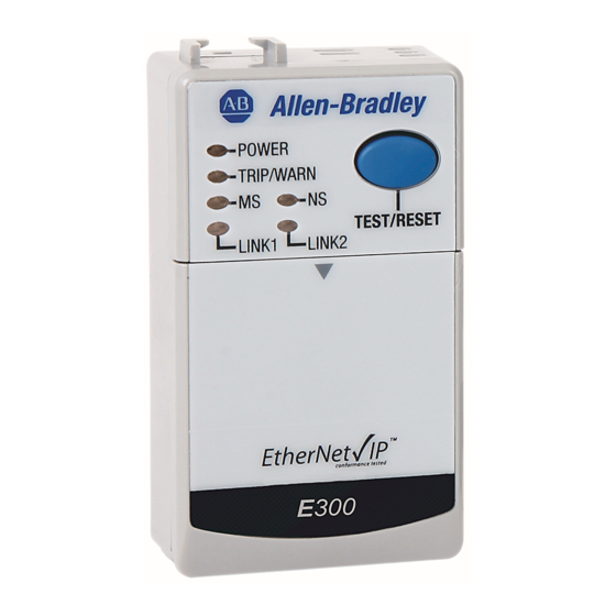
All E300 relay Communication Modules and Operator Station have two diagnostic status indicators: Power LED and Trip/Warn LED. You can use these diagnostic status indicators to help identify the state of the E300 relay and the reason for the trip or warning event. -
Page 210: Module Status (Ms)
One or more EtherNet/IP connections timed out. Reset the E300 EtherNet/IP Communication Module. Flashing Reset the E300 EtherNet/IP Communication Module or verify the validity of the data in the The E300 Overload Relay is in a fault state. configuration assembly. -
Page 211: Network Status (Ns)
Trip/Warn The E300 relay Power LED identifies the reason for the trip or warning event. The E300 relay displays a long and short blinking pattern to identify the reason for the trip or warning event. Table 50 - Trip / Warn LED for EtherNet/IP and DeviceNet Communication Modules... - Page 212 Chapter 12 Troubleshooting Table 51 lists the blink patterns for the E300 relay trip and warning events. Table 51 - Blink Patterns for Trip/Warn Events Code Long Blink Pattern Short Blink Pattern Overload Phase Loss Ground Fault Current Stall Underload...
-
Page 213: Reset A Trip
ATTENTION: Resetting a trip does not correct the cause for the trip. Take corrective action before you reset the trip. The E300 relay trip condition can be reset by taking one of the following actions: • Actuating the Blue Trip/Reset button on the E300 relay Communication Module •... -
Page 214: Trip/Warn Led Troubleshooting
Chapter 12 Troubleshooting Trip/Warn LED Troubleshooting Trip Description Possible Cause Corrective Action Test Trip 1. Operation of the Test/Reset 1. Operate the Test/Reset button to clear 1. Motor overloaded 1. Check and correct source of overload (load, mechanical transmission components, motor bearings). Overload 2. - Page 215 Troubleshooting Chapter 12 Trip Description Possible Cause Corrective Action 1. Operating Time (Parameter 28) is equal to Total Operating or greater than the value set in Total 1. Clear Command (Parameter 165) to "Clear Operating Statistics" to reset Operating Time (Parameter 28) Hours Warning Operating Hours (Parameter 208) 1.
- Page 216 Chapter 12 Troubleshooting Rockwell Automation Publication 193-UM015F-EN-P - August 2018...
-
Page 217: E300 Wiring Configurations
Appendix Wiring Diagrams E300 Wiring Configurations The following pages illustrate various wiring configurations for the E300™ Electronic Overload Relay Figure 83 - Delta Configuration with Two Potential Transformers (Open Delta) Delta Source Signal filter and short-circuit protection Signal filter and... - Page 218 Appendix A Wiring Diagrams Figure 84 - Wye Configuration with Two Potential Transformers (Open Delta) Wye Source Grounded or ungrounded neutral Signal filter and short-circuit protection Signal filter and short-circuit protection Signal filter and short-circuit protection Signal filter and short-circuit protection 10 M 10 M...
- Page 219 Wiring Diagrams Appendix A Figure 85 - Grounded B Phase Configuration With Two Potential Transformers (Open Delta) Grounded B Phase Delta Source Signal filter and short-circuit protection Signal filter and short-circuit protection Signal filter and short-circuit protection Signal filter and short-circuit protection 10 M...
- Page 220 Appendix A Wiring Diagrams Figure 86 - Delta Configuration with Three Potential Transformers (Delta-to-Delta) Delta Source Signal filter and short-circuit protection Signal filter and short-circuit protection Signal filter and short-circuit protection Signal filter and short-circuit protection 10 M 10 M 10 M Delta to Delta Potential Transformer...
- Page 221 Wiring Diagrams Appendix A Figure 87 - Wye Configuration with Three Potential Transformers (Delta-to-Delta) Wye Source Grounded or ungrounded neutral Signal filter and short-circuit protection Signal filter and short-circuit protection Signal filter and short-circuit protection Signal filter and short-circuit protection 10 M 10 M 10 M...
- Page 222 Appendix A Wiring Diagrams Figure 88 - Delta Configuration with Three Potential Transformers (Wye-to-Wye) Delta Source Signal filter and short-circuit protection Signal filter and short-circuit protection Signal filter and short-circuit protection Signal filter and short-circuit protection 10 M 10 M 10 M Delta Load Wye to Wye Potential...
- Page 223 Wiring Diagrams Appendix A Figure 89 - Wye Configuration with Three Potential Transformers (Wye-to-Wye) Wye Source Grounded or ungrounded neutral Signal filter and short-circuit protection Signal filter and short-circuit protection Signal filter and short-circuit protection Signal filter and short-circuit protection 10 M 10 M 10 M...
- Page 224 Appendix A Wiring Diagrams Figure 90 - Delta Configuration with Wye-to-Delta Potential Transformers Delta Source Signal filter and short-circuit protection Signal filter and short-circuit protection Signal filter and short-circuit protection Signal filter and short-circuit protection 10 M 10 M 10 M Wye to Delta Potential Delta Load Transformer...
- Page 225 Wiring Diagrams Appendix A Figure 91 - Wye Configuration with Wye-to-Delta Potential Transformers Wye Source Grounded or ungrounded neutral Signal filter and short-circuit protection Signal filter and short-circuit protection Signal filter and short-circuit protection Signal filter and short-circuit protection 10 M 10 M 10 M Wye to Delta Potential...
- Page 226 Appendix A Wiring Diagrams Figure 92 - Delta Configuration with Delta-to-Wye Potential Transformers Delta Source Signal filter and short-circuit protection Signal filter and short-circuit protection Signal filter and short-circuit protection Signal filter and short-circuit protection 10 M 10 M 10 M Delta to Wye Potential Transformer Delta Load...
- Page 227 Wiring Diagrams Appendix A Figure 93 - Wye with Delta-to-Wye Potential Transformers Wye Source Grounded or ungrounded neutral Signal filter and short-circuit protection Signal filter and short-circuit protection Signal filter and short-circuit protection Signal filter and short-circuit protection 10 M 10 M 10 M Delta to Wye Potential...
- Page 228 Appendix A Wiring Diagrams Notes: Rockwell Automation Publication 193-UM015F-EN-P - August 2018...
-
Page 229: Identity Object - Class Code 0X0001
Appendix Common Industrial Protocol (CIP) Objects The E300™ Electronic Overload Relay’s EtherNet/IP Communication Module supports the following Common Industrial Protocol (CIP). Table 52 - CIP Object Classes Class Object 0x0001 Identity 0x0002 Message Router 0x0003 DeviceNet 0x0004 Assembly 0x0005 Connection... - Page 230 Table Table 55 - Identity Object Instance 1 Attributes Attribute ID Access Rule Name Data Type Value Vendor UINT 1 = Allen-Bradley Device Type UINT Product Code UINT Revision Structure of: Major Revision USINT Firmware revision of the Control firmware...
- Page 231 Instance 2 of the Identity Object contains the attributes in Table Table 57 - Identity Object Instance 2 Attributes Attribute ID Access Rule Name Data Type Value Vendor UINT 1 = Allen-Bradley Device Type UINT Product Code UINT Revision Structure of: Major Revision USINT...
-
Page 232: Message Router - Class Code 0X0002
Table Table 58 - Identity Object Instance 3 Attributes Attribute Access Name Data Type Value Rule Vendor UINT 1 = Allen-Bradley Device Type UINT Product Code UINT Revision Structure of: Major Revision USINT Firmware revision of the Sensing Module firmware... -
Page 233: Instance 2
Trip Status Required ODVA Produced Instance Produced DataLinks Object 8 Datalinks Produced Assembly Config Configuration Configuration Assembly Consumed E300 Consumed Default Consumed Assembly Produced Current Diags Produced Assembly with Current Diagnostics Only Produced All Diags Default Produced Assembly Instance 2 Table 64 summarizes Attribute 3 Format. -
Page 234: Instance 50
Appendix B Common Industrial Protocol (CIP) Objects Table 65 - Instance 2 Attributes Attribute Access Member Name Data Type Value Rule Index Number of Members in Member UINT List Member List Array of STRUCT Member Data Description UINT Member Path Size UINT Member Path Packed EPATH... -
Page 235: Instance 120 - Configuration Assembly Revision 2
Common Industrial Protocol (CIP) Objects Appendix B Instance 120 - Configuration Assembly Revision 2 Table 68 shows Attribute 3 Format and Attribute 2 Member List for revision 2 of the assembly. Table 68 - Instance 120 — Configuration Assembly DINT 15 Size (bits) Param ConfigAssyRev = 2 1100... - Page 236 Appendix B Common Industrial Protocol (CIP) Objects DINT 15 Size (bits) Param OperStationType DigitalMod1Type DigitalMod2Type DigitalMod3Type DigitalMod4Type AnalogMod1Type AnalogMod2Type AnalogMod3Type AnalogMod4Type Reserved Language OutAAssignment OuBAssignment OutCAssignment InPt00Assignment InPt01Assignment InPt02Assignment InPt03Assignment InPt04Assignment InPt05Assignment ActFLA2wOutput EmergencyStartEn Reserved StartsPerHour Reserved StartsInterval PMTotalStarts PMOperatingHours FeedbackTimeout TransitionDelay InterlockDelay...
- Page 237 Common Industrial Protocol (CIP) Objects Appendix B DINT 15 Size (bits) Param CIInhibitTime CITripDelay CITripLevel CIWarningLevel CTPrimary CTSecondary UCInhibitTime L1UCTripDelay L1UCTripLevel L1UCWarningLevel L2UCTripDelay L2UCTripLevel L2UCWarningLevel L3UCTripDelay L3UCTripLevel L3UCWarningLevel OCInhibitTime L1OCTripDelay L1OCTripLevel L1OCWarningLevel L2OCTripDelay L2OCTripLevel L2OCWarningLevel L3OCTripDelay L3OCTripLevel L3OCWarningLevel LineLossInhTime L1LossTripDelay L2LossTripDelay L3LossTripDelay Datalink0...
- Page 238 Appendix B Common Industrial Protocol (CIP) Objects DINT 15 Size (bits) Param OutPt00PrFltAct OutPt00PrFltVal OutPt00ComFltAct OutPt00ComFltVal OutPt00ComIdlAct OutPt00ComIdlVal OutPt01PrFltAct OutPt01PrFltVal OutPt01ComFltAct OutPt01ComFltVal OutPt01ComIdlAct OutPt01ComIdlVal OutPt02PrFltAct OutPt02PrFltVal OutPt02ComFltAct OutPt02ComFltVal OutPt02ComIdlAct OutPt02ComIdlVal OutDig1PrFltAct OutDig1PrFltVal OutDig1ComFltAct OutDig1ComFltVal OutDig1ComIdlAct OutDig1ComIdlVal OutDig2PrFltAct OutDig2PrFltVal OutDig2ComFltAct OutDig2ComFltVal OutDig2ComIdlAct OutDig2ComIdlVal OutDig3PrFltAct...
- Page 239 Common Industrial Protocol (CIP) Objects Appendix B DINT 15 Size (bits) Param VoltageMode PhRotInhibitTime UVInhibitTime UVTripDelay UVTripLevel UVWarningLevel OVInhibitTime OVTripDelay OVTripLevel OVWarningLevel VUBInhibitTime VUBTripDelay VUBTripLevel VUBWarningLevel UFInhibitTime UFTripDelay UFTripLevel UFWarningLevel OFInhibitTime OFTripDelay OFTripLevel OFWarningLevel DemandPeriod NumberOfPeriods UWInhibitTime UWTripDelay OWInhibitTime OWTripDelay UWTripLevel UWWarningLevel OWTripLevel...
- Page 240 Appendix B Common Industrial Protocol (CIP) Objects DINT 15 Size (bits) Param UVARGInhibitTime UVARGTripDelay OVARGInhibitTime OVARGTripDelay UVARGTripLevel UVARGWarnLevel OVARGTripLevel OVARGWarnLevel UVAInhibitTime UVATripDelay OVAInhibitTime OVATripDelay UVATripLevel UVAWarningLevel OVATripLevel OVAWarningLevel UPFLagInhibTime UPFLagTripDelay UPFLagTripLevel UPFLagWarnLevel OPFLagInhibTime OPFLagTripDelay OPFLagTripLevel OPFLagWarnLevel UPFLeadInhibTime UPFLeadTripDelay UPFLeadTripLevel UPFLeadWarnLevel OPFLeadInhibTime OPFLeadTripDelay OPFLeadTripDelay...
- Page 241 Common Industrial Protocol (CIP) Objects Appendix B DINT 15 Size (bits) Param InAMod1C0TripDly InAMod1C1TripDly InAMod1C2TripDly Reserved 1102 InAMod1C0TripLvl InAMod1C0WarnLvl InAMod1C1TripLvl InAMod1C1WarnLvl InAMod1C2TripLvl InAMod1C2WarnLvl InAnMod1Ch00Type InAnMod1Ch01Type InAnMod1Ch02Type Reserved 1101 OutAnMod1Select InAMod1Ch0Format InAMod1C0FiltFrq InAMod1C0OpCktSt InAMod1Ch1Format InAMod1C1FiltFrq InAMod1C1OpCktSt InAMod1Ch2Format InAMod1C2FiltFrq InAMod1C2OpCktSt InAMod1C0TmpUnit InAnMod1Ch0RTDEn InAMod1C1TmpUnit InAnMod1Ch1RTDEn InAMod1C2TmpUnit...
- Page 242 Appendix B Common Industrial Protocol (CIP) Objects DINT 15 Size (bits) Param InAnMod2Ch00Type InAnMod2Ch01Type InAnMod2Ch02Type Reserved 1101 OutAnMod2Select InAMod2Ch0Format InAMod2C0FiltFrq InAMod2C0OpCktSt InAMod2Ch1Format InAMod2C1FiltFrq InAMod2C1OpCktSt InAMod2Ch2Format InAMod2C2FiltFrq InAMod2C2OpCktSt InAMod2C0TmpUnit InAnMod2Ch0RTDEn InAMod2C1TmpUnit InAnMod2Ch1RTDEn InAMod2C2TmpUnit InAnMod2Ch2RTDEn OutAnMod2FltActn OutAnMod2dlActn OutAnMod2Type Reserved 1101 InAMod3C0TripDly InAMod3C1TripDly InAMod3C2TripDly Reserved 1102...
- Page 243 Common Industrial Protocol (CIP) Objects Appendix B DINT 15 Size (bits) Param InAMod3Ch1Format InAMod3C1FiltFrq InAMod3C1OpCktSt InAMod3Ch2Format InAMod3C2FiltFrq InAMod3C2OpCktSt InAMod3C0TmpUnit InAnMod3Ch0RTDEn InAMod3C1TmpUnit InAnMod3Ch1RTDEn InAMod3C2TmpUnit InAnMod3Ch2RTDEn OutAnMod3FltActn OutAnMod3dlActn OutAnMod3Type Reserved 1101 InAMod4C0TripDly InAMod4C1TripDly InAMod4C2TripDly Reserved 1102 InAMod4C0TripLvl InAMod4C0WarnLvl InAMod4C1TripLvl InAMod4C1WarnLvl InAMod4C2TripLvl InAMod4C2WarnLvl InAnMod4Ch00Type InAnMod4Ch01Type InAnMod4Ch02Type...
-
Page 244: Instance 120 - Configuration Assembly Revision 1
Appendix B Common Industrial Protocol (CIP) Objects Instance 120 - Configuration Assembly Revision 1 Table 69 shows Attribute 3 Format and Attribute 2 Member List for revision 1 of the assembly. This is a stripped down simple version of a config assembly. Table 69 - Instance 120 —... - Page 245 Common Industrial Protocol (CIP) Objects Appendix B DINT 15 Size (bits) Param OutputStatus OpStationStatus TripStsCurrent WarnStsCurrent TripStsVoltage WarnStsVoltage TripStsPower WarnStsPower TripStsControl WarnStsControl TripStsAnalog WarnStsAnalog Reserved 1103 MismatchStatus ThermUtilizedPct CurrentImbal AvgPercentFLA AverageCurrent L1Current L2Current L3Current GFCurrent Reserved 1103 Datalink1 1291 Datalink2 1292 Datalink3 1293...
-
Page 246: Instance 199 - All Diagnostics Produced Assembly
Appendix B Common Industrial Protocol (CIP) Objects DINT 15 Size (bits) Param InAnMod2Ch00 InAnMod2Ch01 InAnMod2Ch02 Reserved 1103 InAnMod3Ch00 InAnMod3Ch01 InAnMod3Ch02 Reserved 1103 InAnMod4Ch00 InAnMod4Ch01 InAnMod4Ch02 Reserved 1103 Instance 199 - All Diagnostics Produced Assembly Table 72 - Instance 199 - All Diagnostics Produced Assembly DINT 15 Size (bits) Param Reserved for Logix... - Page 247 Common Industrial Protocol (CIP) Objects Appendix B DINT 15 Size (bits) Param GFCurrent Reserved 1103 AvgVoltageLtoL L1toL2Voltage L2toL3Voltage L3toL1Voltage TotalRealPower TotalReactivePwr TotalApparentPwr TotalPowerFactor Datalink0 1291 Datalink1 1292 Datalink2 1293 Datalink3 1294 Datalink4 1295 Datalink5 1296 Datalink6 1297 Datalink7 1298 PtDeviceOuts AnDeviceOuts 1105 InAnMod1Ch00...
-
Page 248: Connection Object - Class Code 0X0005
Appendix B Common Industrial Protocol (CIP) Objects Connection Object — CLASS CODE 0x0005 No class attributes are supported for the Connection Object Multiple instances of the Connection Object are supported, instances 1, 2 and 4 from the group 2 predefined master/slave connection set, and instances 5-7 are available explicit UCMM connections. - Page 249 Common Industrial Protocol (CIP) Objects Appendix B Instance 2 is the Predefined Group 2 Connection Set Polled IO Message Connection. The instance 2 attributes in Table 74 are supported: Table 74 - Connection Object — CLASS CODE 0x0005 Instance 2 Attributes Attribute ID Access Rule Name Data...
- Page 250 Appendix B Common Industrial Protocol (CIP) Objects Instance 4 is the Predefined Group 2 Connection Set Change of State / Cyclic I/O Message Connection. The instance 4 attributes in Table 75 are supported: Table 75 - Connection Object — CLASS CODE 0x0005 Instance 4 Attributes Attribute ID Access Rule Name Data Type Value...
-
Page 251: Discrete Input Point Object - Class Code 0X0008
Common Industrial Protocol (CIP) Objects Appendix B Instances 5 - 7 are available group 3 explicit message connections that are allocated through the UCMM. The attributes in Table 76 are supported: Table 76 - Connection Object — CLASS CODE 0x0005 Instance 5…7 Attributes Attribute ID Access Rule Name Data Type Value 0=nonexistant... -
Page 252: Discrete Output Point Object - Class Code 0X0009
Appendix B Common Industrial Protocol (CIP) Objects InputPt02 Control Module Input 2 InputPt03 Control Module Input 3 InputPt04 Control Module Input 4 InputPt05 Control Module Input 5 InputDigMod1Pt00 Digital Expansion Module 1 Input 0 InputDigMod1Pt01 Digital Expansion Module 1 Input 1 InputDigMod1Pt02 Digital Expansion Module 1 Input 2 InputDigMod1Pt03... -
Page 253: Analog Input Point Object - Class Code 0X000A
Common Industrial Protocol (CIP) Objects Appendix B Table 83 - Discrete Output Point Object Instances Instance Name Description OutputPt00 Control Module Output 0 OutputPt01 Control Module Output 1 OutputPt02 Control Module Output 2 OutDigMod1Pt00 Digital Expansion Module 1 Output 0 OutDigMod1Pt01 Digital Expansion Module 1 Output 1 OutDigMod2Pt00... -
Page 254: Parameter Object - Class Code 0X000F
Appendix B Common Industrial Protocol (CIP) Objects Table 86 - Analog Input Point Object Class Attributes Attribute ID Access Rule Name Data Type Value Revision UINT Max. Instance UINT 12 Instances of the Analog Input Point Object are supported. The raw analog value is scaled appropriately to the analog input configuration parameters and the scaled value are placed in the Value attribute. -
Page 255: Parameter Group Object - Class Code 0X0010
Common Industrial Protocol (CIP) Objects Appendix B Attribute ID Access Rule Name Data Type Value Parameter Class Descriptor WORD 0x03 Configuration Assembly Instance UINT Native Language UINT 1 = English The instance attributes in Table 91 are implemented for all parameter attributes. Table 91 - Parameter Object Instance Attributes Attribute ID Access Rule Name... -
Page 256: Discrete Output Group Object - Class Code 0X001E
Appendix B Common Industrial Protocol (CIP) Objects The instance attributes in Table 94 are supported for all parameter group instances and are implemented for all parameter attributes. Table 94 - Parameter Group Object Instance Attributes Attribute ID Access Rule Name Data Type Value Group Name String... -
Page 257: Control Supervisor Object - Class Code 0X0029
Common Industrial Protocol (CIP) Objects Appendix B Get/Set Idle Value BOOL 0=OFF, 1=ON Get/Set Pr Fault Action BOOL 0=Pr Fault Value Attribute, 1=Ignore Get/Set Pr Fault Value BOOL 0=OFF, 1=ON The common services in Table 98are implemented for the Discrete Output Group Object. -
Page 258: Base Energy Object - Class Code 0X004E
Appendix B Common Industrial Protocol (CIP) Objects Attribute ID Access Rule Name Data Type Value Current L2 xxx.x Amps (tenths of amps) Current L3 xxx.x Amps (tenths of amps) GF Current 0.00 – 12.75 Amps The common services in Table 102 are implemented for the Overload Object. -
Page 259: Electrical Energy Object - Class Code 0X004F
Common Industrial Protocol (CIP) Objects Appendix B Table 105 - Base Energy Object Common Services Service Code Implemented for: Service Name Class Instance 0x01 GetAttributes_All 0x05 Reset 0x0E Get_Attribute_Single 0x10 Set_Attribute_Single Table 106 describes the Get_Attributes_All response. Table 106 - Base Energy Object Class Attributes Get_Attributes_All Response Attribute ID Data Type Name... - Page 260 Appendix B Common Industrial Protocol (CIP) Objects Attribute ID Access Rule Name Data Type Value Reactive Energy ODOMETER Returns params 90-94 values. Generated Odometer Reactive Energy Net SIGNED ODOMETER Returns params 95-99 values. Odometer Apparent Energy ODOMETER Returns params 100-104 values. Odometer Line Frequency REAL...
- Page 261 Common Industrial Protocol (CIP) Objects Appendix B Table 109 describes the Get_Attributes_All response. Table 109 - Electrical Energy Object Class Attributes Get_Attributes_All Response Attribute ID Data Type Name Value Array[5] of INT Real Energy Consumed Odometer Attribute 1 Value Array[5] of INT Real Energy Generated Odometer 0.0.0.0.0 Array[5] of INT Real Energy Net Odometer...
-
Page 262: Wall Clock Time Object - Class Code 0X008B
Appendix B Common Industrial Protocol (CIP) Objects Wall Clock Time Object — CLASS CODE 0x008B The class attributes in Table 110are supported: Table 110 - Wall Clock Time Object Class Attributes Attribute ID Access Rule Name Data Type Value Object Revision UINT Number of Instances UINT... -
Page 263: Dpi Fault Object - Class Code 0X0097
Common Industrial Protocol (CIP) Objects Appendix B Attribute Access Rule Name Data Type Value The number of minutes to be adjusted for Set / SSV DST Adjustment daylight saving time It specifies if we are in daylight saving time or Set / SSV Enable DST USINT... - Page 264 Appendix B Common Industrial Protocol (CIP) Objects Table 114 - DPI Fault Object Instance Attributes Attribute ID Access Rule Name Data Type Value Full / All Info Struct of: Fault Code UINT Table 115 Fault Source Struct of: DPI Port Number USINT Device Object USINT...
- Page 265 Common Industrial Protocol (CIP) Objects Appendix B Fault Code Fault Text Help Text L3OverCurrenTrip L3 Current was over L3 Overcurrent Level longer than Trip Delay L1LineLossTrip L1 Current Lost for longer than the L1 Loss Trip Delay L2LineLossTrip L2 Current Lost for longer than the L2 Loss Trip Delay L3LineLossTrip L3 Current Lost for longer than the L3 Loss Trip Delay UnderVoltageTrip...
-
Page 266: Dpi Warning Object - Class Code 0X0098
Appendix B Common Industrial Protocol (CIP) Objects Fault Code Fault Text Help Text Trip63 Trip64 InAnMod1Ch00Trip Input Channel 00 on Analog Module 1 exceeded its Trip Level InAnMod1Ch01Trip Input Channel 01 on Analog Module 1 exceeded its Trip Level InAnMod1Ch02Trip Input Channel 02 on Analog Module 1 exceeded its Trip Level InAnMod2Ch00Trip Input Channel 00 on Analog Module 2 exceeded its Trip Level... - Page 267 Common Industrial Protocol (CIP) Objects Appendix B Attribute ID Access Rule Name Data Type Value Get/Set Warning Cmd Write USINT 0=NOP 2=Clear Queue The instance of the Warning Queue Warning Instance Read UINT Entry containing information about the most recent warning The number of Warning recorded in Number of Recorded Faults UINT the Warning Queue...
- Page 268 Appendix B Common Industrial Protocol (CIP) Objects Warning Warning Text Warning Help Text Code Ground Fault Power conductor or motor winding is shorting to ground Warning4 JamWarning Motor current has exceed the programmed jam warning level UnderloadWarning Motor current has fallen below normal operating levels Current ImbalWarn Phase to phase current imbalance detected L1UnderCurrWarn...
- Page 269 Common Industrial Protocol (CIP) Objects Appendix B Warning Warning Text Warning Help Text Code Warning52 Warning53 Warning54 Warning55 ConfigWarning Invalid parameter config. See parameters 38-39 for details Warning57 DLXFBTimeoutWarn DeviceLogix Feedback Timeout Trip was detected Warning59 PM Starts Number of Starts Warning Level Exceeded PM Oper Hours Operating Hours Warning Level Exceeded Warning62...
-
Page 270: Mcc Object - Class Code 0X00C2
Appendix B Common Industrial Protocol (CIP) Objects MCC Object — CLASS CODE 0x00C2 A single instance (instance 1) of the MCC Object is supported: Table 121 - MCC Object Instance Attributes Attribute ID Access Rule Name Data Type Range Value Get/Set Mcc Number USINT... -
Page 271: Devicenet I/O Instances
Appendix DeviceNet I/O Assemblies DeviceNet I/O Instances The E300™ Electronic Overload Relay’s DeviceNet Communication Module supports the following I/O Instances. Table 123 - DeviceNet I/O Instances Instance Name Page Basic Overload Input Assembly Datalinks Produced Assembly Configuration Assembly - Large Configuration... - Page 272 Appendix C DeviceNet I/O Assemblies Table 126 - Instance 100—Datalinks Produced Assembly Instance 100—Datalinks Produced Assembly Member Size Path DINT Reserved for Logix 1104 Datalink0 Datalink1 Datalink2 Datalink3 Datalink4 Datalink5 Datalink6 Datalink7 Rockwell Automation Publication 193-UM015F-EN-P - August 2018...
- Page 273 DeviceNet I/O Assemblies Appendix C Table 127 - Instance 100 Attributes Attribute ID Access Rule Member Index Name Data Type Value Number of Members in Member List UINT Member List Array of STRUCT Member Data Description UINT Member Path Size UINT Member Path Packed EPATH...
- Page 274 Appendix C DeviceNet I/O Assemblies Table 129 - Instance 120—Configuration Assembly Instance 120—Configuration Assembly Member Size Param INT DINT ConfigAssyRev =2 Delivery Mechanism Header * 2 - 1 1100 SetOperatingMode Reserved 1102 FLASetting FLA2Setting TripClass OLPTCResetMode SingleOrThreePh GFFilter GFMaxInghibit PhaseRotTrip PowerScale VoltageScale OLResetLevel...
- Page 275 DeviceNet I/O Assemblies Appendix C Instance 120—Configuration Assembly Member Size Param INT DINT OperStationType DigitalMod1Type DigitalMod2Type DigitalMod3Type DigitalMod4Type AnalogMod1Type AnalogMod2Type AnalogMod3Type AnalogMod4Type Reserved Language OutAAssignment OuBAssignment OutCAssignment InPt00Assignment InPt01Assignment InPt02Assignment InPt03Assignment InPt04Assignment InPt05Assignment ActFLA2wOutput EmergencyStartEn Reserved StartsPerHour OutPt00FnlFltVal OutPt01FnlFltVal OutPt02FnlFltVal OutDig1FnlFltVal OutDig2FnlFltVal OutDig3FnlFltVal...
- Page 276 Appendix C DeviceNet I/O Assemblies Instance 120—Configuration Assembly Member Size Param INT DINT StallTripLevel JamInhibitTime JamTripDelay JamTripLevel JamWarningLevel ULInhibitTime ULTripDelay ULTripLevel ULWarningLevel CIInhibitTime CITripDelay CITripLevel CIWarningLevel CTPrimary CTSecondary UCInhibitTime L1UCTripDelay L1UCTripLevel L1UCWarningLevel L2UCTripDelay L2UCTripLevel L2UCWarningLevel L3UCTripDelay L3UCTripLevel L3UCWarningLevel OCInhibitTime L1OCTripDelay L1OCTripLevel L1OCWarningLevel L2OCTripDelay...
- Page 277 DeviceNet I/O Assemblies Appendix C Instance 120—Configuration Assembly Member Size Param INT DINT OutPt00PrFltAct OutPt00PrFltVal OutPt00ComFltAct OutPt00ComFltVal OutPt00ComIdlAct OutPt00ComIdlVal OutPt01PrFltAct OutPt01PrFltVal OutPt01ComFltAct OutPt01ComFltVal OutPt01ComIdlAct OutPt01ComIdlVal OutPt02PrFltAct OutPt02PrFltVal OutPt02ComFltAct OutPt02ComFltVal OutPt02ComIdlAct OutPt02ComIdlVal OutDig1PrFltAct OutDig1PrFltVal OutDig1ComFltAct OutDig1ComFltVal OutDig1ComIdlAct OutDig1ComIdlVal OutDig2PrFltAct OutDig2PrFltVal OutDig2ComFltAct OutDig2ComFltVal OutDig2ComIdlAct OutDig2ComIdlVal...
- Page 278 Appendix C DeviceNet I/O Assemblies Instance 120—Configuration Assembly Member Size Param INT DINT PTPrimary PTSecondary VoltageMode PhRotInhibitTime UVInhibitTime UVTripDelay UVTripLevel UVWarningLevel OVInhibitTime OVTripDelay OVTripLevel OVWarningLevel VUBInhibitTime VUBTripDelay VUBTripLevel VUBWarningLevel UFInhibitTime UFTripDelay UFTripLevel UFWarningLevel OFInhibitTime OFTripDelay OFTripLevel OFWarningLevel DemandPeriod NumberOfPeriods UWInhibitTime UWTripDelay OWInhibitTime OWTripDelay...
- Page 279 DeviceNet I/O Assemblies Appendix C Instance 120—Configuration Assembly Member Size Param INT DINT OVARCWarnLevel UVARGInhibitTime UVARGTripDelay OVARGInhibitTime OVARGTripDelay UVARGTripLevel UVARGWarnLevel OVARGTripLevel Instance 120 - Configuration Assembly Member Size Param OVARGWarnLevel UVAInhibitTime UVATripDelay OVAInhibitTime OVATripDelay UVATripLevel UVAWarningLevel OVATripLevel OVAWarningLevel UPFLagInhibTime UPFLagTripDelay UPFLagTripLevel UPFLagWarnLevel OPFLagInhibTime...
- Page 280 Appendix C DeviceNet I/O Assemblies Instance 120—Configuration Assembly Member Size Param INT DINT Screen4Param1 Screen4Param2 DisplayTimeout Reserved 1103 InAMod1C0TripDly InAMod1C1TripDly InAMod1C2TripDly Reserved 1102 InAMod1C0TripLvl InAMod1C0WarnLvl InAMod1C1TripLvl InAMod1C1WarnLvl InAMod1C2TripLvl InAMod1C2WarnLvl InAnMod1Ch00Type InAnMod1Ch01Type InAnMod1Ch02Type Reserved 1101 OutAnMod1Select InAMod1Ch0Format InAMod1C0FiltFrq InAMod1C0OpCktSt InAMod1Ch1Format InAMod1C1FiltFrq InAMod1C1OpCktSt InAMod1Ch2Format InAMod1C2FiltFrq...
- Page 281 DeviceNet I/O Assemblies Appendix C Instance 120—Configuration Assembly Member Size Param INT DINT InAMod2C2TripLvl InAMod2C2WarnLvl InAnMod2Ch00Type InAnMod2Ch01Type InAnMod2Ch02Type Reserved 1101 OutAnMod2Select InAMod2Ch0Format InAMod2C0FiltFrq InAMod2C0OpCktSt InAMod2Ch1Format InAMod2C1FiltFrq InAMod2C1OpCktSt InAMod2Ch2Format InAMod2C2FiltFrq InAMod2C2OpCktSt InAMod2C0TmpUnit InAnMod2Ch0RTDEn InAMod2C1TmpUnit InAnMod2Ch1RTDEn InAMod2C2TmpUnit InAnMod2Ch2RTDEn OutAnMod2EfltAct OutAnMod2PfltAct OutAnMod2Type Reserved 1101 InAMod3C0TripDly InAMod3C1TripDly...
- Page 282 Appendix C DeviceNet I/O Assemblies Instance 120—Configuration Assembly Member Size Param INT DINT InAMod3Ch1Format InAMod3C1FiltFrq InAMod3C1OpCktSt InAMod3Ch2Format InAMod3C2FiltFrq InAMod3C2OpCktSt InAMod3C0TmpUnit InAnMod3Ch0RTDEn InAMod3C1TmpUnit InAnMod3Ch1RTDEn InAMod3C2TmpUnit InAnMod3Ch2RTDEn OutAnMod3EfltAct OutAnMod3PfltAct OutAnMod3Type Reserved 1101 InAMod4C0TripDly InAMod4C1TripDly InAMod4C2TripDly Reserved 1102 InAMod4C0TripLvl InAMod4C0WarnLvl InAMod4C1TripLvl InAMod4C1WarnLvl InAMod4C2TripLvl InAMod4C2WarnLvl InAnMod4Ch00Type InAnMod4Ch01Type...
- Page 283 DeviceNet I/O Assemblies Appendix C Instance 120—Configuration Assembly Member Size Param INT DINT InAMod4Ch1Format InAMod4C1FiltFrq InAMod4C1OpCktSt InAMod4Ch2Format InAMod4C2FiltFrq InAMod4C2OpCktSt InAMod3C0TmpUnit InAnMod4Ch0RTDEn InAMod4C1TmpUnit InAnMod4Ch1RTDEn InAMod4C2TmpUnit InAnMod4Ch2RTDEn OutAnMod4EfltAct OutAnMod4PfltAct OutAnMod4Type Reserved 1001 Table 130 shows a simplified version of Instance 120 of the Assembly. It is not included in the EDS file.
- Page 284 Appendix C DeviceNet I/O Assemblies Table 131 - Instance 144—Default Consumed Assembly Instance 144—Default Consumed Assembly Member Size Path INT DINT OutputStatus0 Param18 NetworkStart1 Symbolic NetworkStart2 Symbolic TripReset Symbolic EmergencyStop Symbolic RemoteTrip Symbolic Reserved HMILED1Green Symbolic HMILED2Green Symbolic HMILED3Green Symbolic HMILED3Red Symbolic HMILED4Red...
- Page 285 DeviceNet I/O Assemblies Appendix C Table 132 - Instance 144 Attributes Attribute ID Access Rule Member Index Name Data Type Value Number of Members in Member List UINT Member List Array of STRUCT Member Data Description UINT Member Path Size UINT Member Path Packed EPATH...
- Page 286 Data Type Value Data UINT See data format above Size UINT Name SHORT_STRING "E300 Consumed" Table 133 - Instance 198 Current Diagnostics Produced Assembly Instance 198—Current Diagnostics Produced Assembly Member Size Path INT DINT Reserved for Logix 1104 DeviceStaus0 DeviceStaus1...
- Page 287 DeviceNet I/O Assemblies Appendix C Instance 198—Current Diagnostics Produced Assembly Member Size Path INT DINT Datalink5 Datalink6 Datalink7 PtDeviceOuts AnDeviceOuts 1105 InAnMod1Ch00 InAnMod1Ch01 InAnMod1Ch02 AnalogMod1Status InAnMod2Ch00 InAnMod2Ch01 InAnMod2Ch02 AnalogMod2Status InAnMod3Ch00 InAnMod3Ch01 InAnMod3Ch02 AnalogMod3Status InAnMod4Ch00 InAnMod4Ch01 InAnMod4Ch02 AnalogMod4Status Rockwell Automation Publication 193-UM015F-EN-P - August 2018...
- Page 288 Appendix C DeviceNet I/O Assemblies Table 134 - Instance 198 Attributes Attribute ID Access Rule Member Index Name Data Type Value Number of Members in Member List UINT Member List Array of STRUCT Member Data Description UINT Member Path Size UINT Member Path Packed EPATH...
- Page 289 DeviceNet I/O Assemblies Appendix C Attribute ID Access Rule Member Index Name Data Type Value Member Path Size UINT Member Path Packed EPATH 21 0F 00 25 08 00 Member Data Description UINT Member Path Size UINT Member Path Packed EPATH 21 0F 00 25 0E 00 Member Data Description UINT...
- Page 290 Appendix C DeviceNet I/O Assemblies Attribute ID Access Rule Member Index Name Data Type Value Member Data Description UINT Member Path Size UINT Member Path Packed EPATH 21 0F 00 27 23 01 Member Data Description UINT Member Path Size UINT Member Path Packed EPATH...
- Page 291 DeviceNet I/O Assemblies Appendix C Attribute ID Access Rule Member Index Name Data Type Value Member Data Description UINT Member Path Size UINT Member Path Packed EPATH 21 0F 00 25 77 00 Member Data Description UINT Member Path Size UINT Member Path Packed EPATH...
- Page 292 Appendix C DeviceNet I/O Assemblies Instance 199—All Diagnostics Produced Assembly Member Size Path INT DINT L1Current L2Current L3Current GFCurrent Reserved 1103 AvgVoltageLtoL L1toL2Voltage L2toL3Voltage L3toL1Voltage TotalRealPower TotalReactivePwr TotalApparentPwr TotalPowerFactor Reserved Datalink0 Datalink1 Datalink2 Datalink3 Datalink4 Datalink5 Datalink6 Datalink7 PtDeviceOuts AnDeviceOuts 1105 InAnMod1Ch00 InAnMod1Ch01...
- Page 293 DeviceNet I/O Assemblies Appendix C Instance 199—All Diagnostics Produced Assembly Member Size Path INT DINT InAnMod3Ch02 AnalogMod3Status InAnMod4Ch00 InAnMod4Ch01 InAnMod4Ch02 AnalogMod4Status Table 136 - Instance 199 Attributes Attribute ID Access Rule Member Index Name Data Type Value Number of Members in Member List UINT Member List Array of STRUCT...
- Page 294 Appendix C DeviceNet I/O Assemblies Table 137 - Instance 131—Basic Overload Instance 131—Basic Overload Member Size Path INT DINT Device Status0 Device Status1 Input Status 0 Input Status 1 Output Status OpStation Status Reserved % Thermal Utilized Average %FLA Average Current Rockwell Automation Publication 193-UM015F-EN-P - August 2018...
- Page 295 DeviceNet I/O Assemblies Appendix C Table 138 - Instance 131 Attributes Attribute ID Access Rule Member Index Name Data Type Value Number of Members in Member List UINT Member List Array of STRUCT Member Data Description UINT Member Path Size UINT Member Path Packed EPATH...
- Page 296 Appendix C DeviceNet I/O Assemblies Table 139 - Instance 132—Starter Status Instance 132—Starter Status Member Size Path INT DINT Device Status0 Device Status1 Input Status 0 Input Status 1 L1 Current L2 Current L3 Current Table 140 - Instance 132 Attributes Attribute ID Access Rule Member Index Name Data Type...
- Page 297 DeviceNet I/O Assemblies Appendix C Table 141 - Instance 133—Short Datalink Instance 133—Short Datalink Member Size Path INT DINT Device Status0 DeviceStatus1 Datalink0 Datalink1 Datalink2 Datalink3 Table 142 - Instance 133 Attributes Attribute ID Access Rule Member Index Name Data Type Value Number of Members in Member List UINT...
- Page 298 Appendix C DeviceNet I/O Assemblies Table 144 - Instance 171 Attributes Attribute ID Access Rule Member Index Name Data Type Value Number of Members in Member List UINT Member List Array of STRUCT Member Data Description UINT Member Path Size UINT Member Path Packed EPATH...
- Page 299 DeviceNet I/O Assemblies Appendix C Table 145 - Instance 172—Analog Input Status Instance 172—Analog Input Status Member Size Path INT DINT Device Status0 Device Status1 Input Status 0 Input Status 1 Output Status OpStation Status AnalogStatus1 AnalogStatus 2 AnalogStatus3 AnalogStatus 4 AnalogInput11 AnalogInput12 AnalogInput13...
- Page 300 Appendix C DeviceNet I/O Assemblies Attribute ID Access Rule Member Index Name Data Type Value Member Path Size UINT Member Path Packed EPATH 21 0F 00 25 7B 00 Member Data Description UINT Member Path Size UINT Member Path Packed EPATH 21 0F 00 25 7C 00 Member Data Description UINT...
- Page 301 DeviceNet I/O Assemblies Appendix C Table 147 - Instance 186—Network Output Status Instance 186—Network Output Status Member Size Path INT DINT Device Status0 Device Status1 Network Output Table 148 - Instance 186 Attributes Attribute ID Access Rule Member Index Name Data Type Value Number of Members in Member List...
- Page 302 Appendix C DeviceNet I/O Assemblies Notes: Rockwell Automation Publication 193-UM015F-EN-P - August 2018...
-
Page 303: Index
Index Symbols connection object, class % TCU 155 code 0x0005 246 % TCU, clear 153 control supervisor object, class code 0x0029 add-on modules 21 expansion bus power supply discrete input point object, class code 0x0008 expansion I/O 21 operator station 22 discrete output group ob- administration mode.See modes ject,... - Page 304 Index wall clock time object, class devicelogix 143 code 0x008B 260 expansion bus fault 145 clear all 154 hardware fault 145 clear command 153 nonvolatile storage fault % TCU 153 all 154 operator station trip 143 history logs 153 preventive maintenance 144 kVAh 153 remote trip 144 kVARh 153...
- Page 305 Index device configuration policy 35 output relay overrides 167 device modes 31 programming 168 device monitor 155 devicelogix protection 143 control module ID 156 DeviceNet Communication control trip status 155 Module 21, 269 control warning status 155 DeviceNet Communications current trip status 155 Module 9 current warning status 155 diagnostic information...
- Page 306 Index kVARh consumed 10^9 160 firmware compatibility 201 kVARh generated 10^0 160 firmware revision number 156 kVARh generated 10^-3 firmware update policy 35 firmware updates 201 kVARh generated 10^3 160 compatibility 201 kVARh generated 10^6 160 frequency 158 kVARh generated 10^9 160 frequency protection 133 kVARh net 10^0 160 FRN See firmware revision...
- Page 307 Index L2 percent FLA 157 L2 power factor 159 jam protection 126 L2 reactive power 158 L2 real power 158 kVA demand 161 L2-L3 voltage 157 kVAh 10^0 160 trip snapshot 166 kVAh 10^-3 160 L2-N voltage 158 kVAh 10^3 160 L3 apparent power 159 kVAh 10^6 160 L3 current 157...
- Page 308 Index minute 156 three-wire control mismatch status 156 modes network and local I/O, two- administration 31 wire control 72 invalid configuration 32 network and local I/O, two- ready 31 wire control with run 32 feedback 74 test 32 network and operator sta- modular design tion 69 overview 18...
- Page 309 Index ule 3 type 34 average 157 digital I/O expansion mod- L1 157 ule 4 type 34 L2 157 enable option match protec- L3 157 tion trip 32 percent thermal capacity uti- enable option match protec- lized 155 tion warning 32 phase loss protection 123 operator station type 33 phase rotation 158...
- Page 310 Index reactive power 137 network and operator sta- real power 136 tion 92 preventive maintenance 144 network and operator sta- programming tion, three-wire con- DeviceLogix 168 trol 95 protection network and operator sta- current based 23 tion, two-wire con- ground fault current based trol 94 network with feedback 81 power based 24...
- Page 311 Index total apaprent power 166 network and operator sta- total apparent power 159 tion 111 total power factor 159, 166 network with feedback 100 total reactive power 159, 166 operator station 102 total real power 158, 166 operator station with feed- trip back 104 reset 211...
- Page 312 Index overvoltage 132 phase rotation 133 undervoltage 131 voltage imbalance 132 warning history 164 wiring diagrams 215 year 156 Rockwell Automation Publication XXXX-X.X.X - Month Year...
- Page 314 Rockwell Automation maintains current product environmental information on its website at http://www.rockwellautomation.com/rockwellautomation/about-us/sustainability-ethics/product-environmental-compliance.page. Allen-Bradley, CopyCat, Connected Components Workbench, EtherNet/IP, E300, DeviceLogix, Logix5000, Rockwell Automation, Rockwell Software, RSLogix, RSNetworx, and Studio 5000 are trademarks of Rockwell Automation, Inc. Trademarks not belonging to Rockwell Automation are property of their respective companies.
Need help?
Do you have a question about the E300 and is the answer not in the manual?
Questions and answers