Allen-Bradley E300 Installation Instructions Manual
Electronic overload relay
Hide thumbs
Also See for E300:
- User manual (736 pages) ,
- Quick start instructions (44 pages) ,
- Installation instructions (4 pages)

Related Manuals for Allen-Bradley E300


Summary of Contents for Allen-Bradley E300
-
Page 1: Table Of Contents
Before You Begin What You Need Assemble the E300 Relay Wire the E300 Relay Set the IP Address E300 Configuration via Rotary Dial Addressing E300 Relay Configuration via the BOOTP/ DHCP Utility Downloading the Electronic Data Sheet (EDS) File Additional Resources... - Page 2 E300 Electronic Overload Relay ATTENTION: Read this document and the documents listed in the Additional Resources section about installation, configuration and operation of this equipment before you install, configure, operate or maintain this product. Users are required to familiarize themselves with installation and wiring instructions in addition to requirements of all applicable codes, laws, and standards.
-
Page 3: North American Hazardous Location Approval
E300 Electronic Overload Relay North American Hazardous Location Approval The following information applies when operating this equipment in hazardous Informations sur l’utilisation de cet équipement en environnements dangereux. locations. Les produits marqués "CL I, DIV 2, GP A, B, C, D" ne conviennent qu'à une utilisation en Products marked "CL I, DIV 2, GP A, B, C, D"... -
Page 4: Introduction
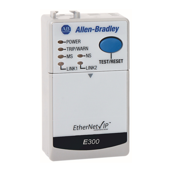
E300 Electronic Overload Relay Introduction This publication explains how to assemble the three module types of the E300™ Electronic Overload Relay, wire the relay, and set the relay IP or node address. Three modules comprise the E300 relay. All three modules are required to make a functional overload relay. You can customize each of the three with accessories to tailor the electronic motor overload for the exact needs of your application. -
Page 5: What You Need
• Standard industrial grade Ethernet or DeviceNet™ cable Assemble the E300 Relay Complete the following steps to assemble the E300 relay. When you have finished, you will be ready to wire and configure the device. IMPORTANT Take caution while assembling each module and add-on component. Small I/O pins can bend and/or break, which causes a module service error once the device is configured. - Page 6 E300 Electronic Overload Relay 2. Connect the E300 relay communication module to the E300 relay control module. Be sure to secure this connection by pushing in the tab shown on the left side of the control module. 3. Install the I/O connectors.
-
Page 7: Wire The E300 Relay
Wire the E300 Relay Complete the device wiring according to the appropriate wiring diagrams for your application. You can wire the E300 relay in multiple ways, depending on the accessories, add-on modules, application requirements, and so on. The wiring diagrams in this section are for illustrative purposes only. - Page 8 E300 Electronic Overload Relay For the E300 Electronic Overload Relay to function properly and protect your motor, it needs a control voltage (24V DC, 120V AC, 240V AC).Connect the control voltage to the device by attaching wires to the A1 (positive) and A2 (negative) terminals, which are located on the bottom of the control module of the E300 relay.
-
Page 9: Set The Ip Address
Set the IP Address You may use one of two methods to configure the IP address for the E300 relay: configuring via the rotary dial addressing, or by using the BOOTP/ DHCP utility. After the IP address is configured, download and install the Electronic Data Sheet (EDS) for RSLinx® Classic and RSLinx Enterprise connectivity software. -
Page 10: E300 Relay Configuration Via The Bootp/ Dhcp Utility
RSLinx™ Classic software. IMPORTANT Before starting the BOOTP/DHCP utility, verify the hardware MAC ID, which is printed on the front of the E300 Relay Communication Module. The MAC ID has a format similar to: 00-0b-db-14-55- 35. - Page 11 (Scanner). Leave node address 63 vacant for introduction of new slave devices. You can change the node address and data rate for E300 relays by using software or by setting the hardware switches that are on the front of each unit. While both methods yield the same result, it is a good practice to choose one method and use it consistently throughout the system.
- Page 12 Using RSNetWorx for DeviceNet Follow these additional steps for node address switch settings in the range of 64…76 and 78…98. To begin the configuration of an E300 relay using software, execute the RSNetWorx software and complete the following procedure. You must use RSNetWorx for DeviceNet Revision 27.00.00 or later.
-
Page 13: Downloading The Electronic Data Sheet (Eds) File
EDS file for the E300 relay using the following steps: 1. Open RSLinx Classic and browse the EtherNet/IP network that has the E300 relay. It is identified with a yellow question mark. Right click on the unrecognized device and select Upload EDS File from Device. - Page 14 12. On the input/output screen in the EDS Wizard, select the Polled checkbox, then enter a value of 8 for Input and 1 for Output. 13. Select Next. RSNetWorx uploads the EDS file from the E300 relay. 14. Select Next to display the icon options for the node.
- Page 15 E300 Electronic Overload Relay Notes: Rockwell Automation Publication 193-IN080A-EN-P - September 2018...
-
Page 16: Additional Resources
Rockwell Automation maintains current product environmental information on its website at http://www.rockwellautomation.com/rockwellautomation/about-us/sustainability-ethics/product-environmental-compliance.page. Allen-Bradley, E300, DeviceLogix, Rockwell Automation, Rockwell Software, RSLinx, and RSNetWorx are trademarks of Rockwell Automation, Inc. Trademarks not belonging to Rockwell Automation are property of their respective companies.
Need help?
Do you have a question about the E300 and is the answer not in the manual?
Questions and answers