Sign In
Upload
Download
Table of Contents
Contents
Add to my manuals
Delete from my manuals
Share
URL of this page:
HTML Link:
Bookmark this page
Add
Manual will be automatically added to "My Manuals"
Print this page
×
Bookmark added
×
Added to my manuals
Manuals
Brands
Martin Audio Manuals
Amplifier
VIA 5002
User manual
Martin Audio VIA 5002 User Manual
Hide thumbs
1
Table Of Contents
2
3
4
5
6
7
8
9
10
11
12
13
14
15
16
17
18
19
20
21
22
23
24
25
26
27
28
29
30
31
32
page
of
32
Go
/
32
Contents
Table of Contents
Bookmarks
Table of Contents
Table of Contents
Important Safety Instructions
Consignes de Sécurité Importantes
Avertissement de Securite
Compliance
For Customers in Europe
For Customers in the Usa
For Customers in Canada
Thanks and Unpacking
Unpacking the Martin Audio VIA Series Amplifier
Installation Instructions
Mechanical Installation
AC Power Connection
Powercon Wiring Instructions
The User Guide
Introduction and Key Features
Introduction
Key Features
Audio Connections
Input Connections
Using Unbalanced Connections
Amplifier Output Connections
Panel Layouts
Via2502
Via2004
Via5002
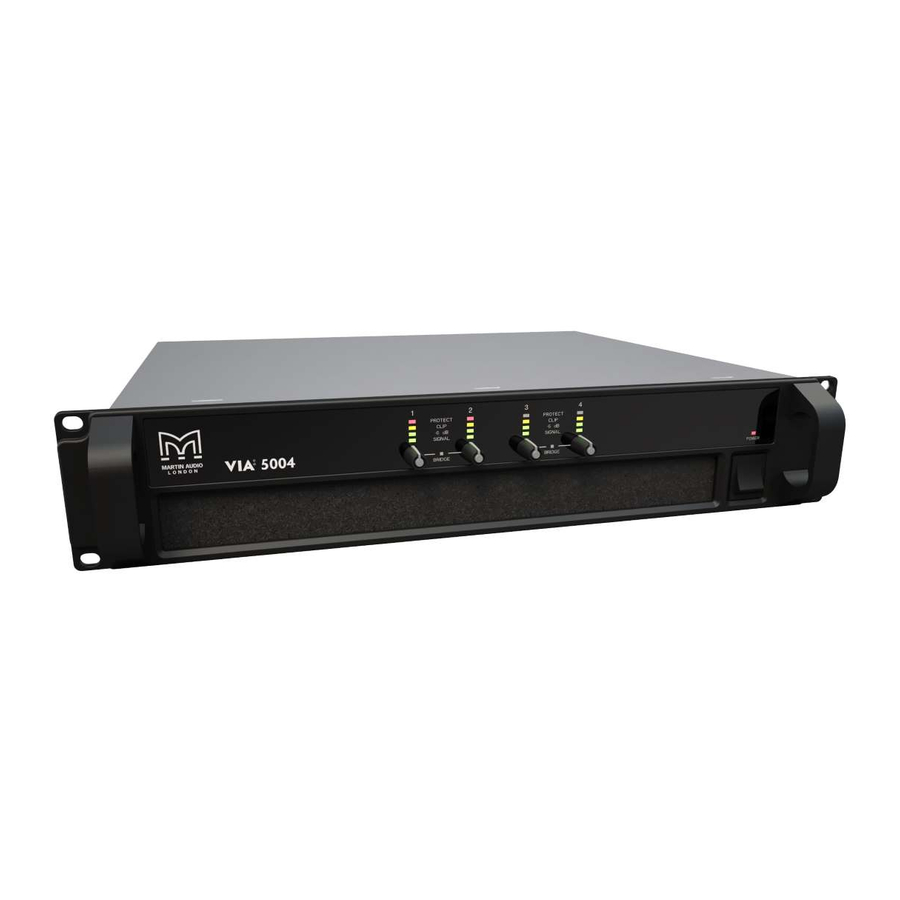
Via5004
Rear Panel
Via2502
Via2004
Via5002
Via5004
Protection
Turn-On-Turn-Off Muting
Short Circuit Protection
Thermal Protection
DC Fault Protection
Input / Output Protection
Operation
Connect Power to the Amplifier
Connect All Input and Output Cables
Gain Controls
Power the System
Bridge Mode
Protection Systems
Technical Specifications
General
Audio
Power Supply
Physical
Technical Drawing
Warranty
Advertisement
Quick Links
Download this manual
V1.0 Nov2018
VIA
Power Amplifiers
User Guide
Table of
Contents
Previous
Page
Next
Page
1
2
3
4
5
Advertisement
Table of Contents
Need help?
Do you have a question about the VIA 5002 and is the answer not in the manual?
Ask a question
Questions and answers
Related Manuals for Martin Audio VIA 5002
Amplifier Martin Audio VIA 2502 User Manual
(32 pages)
Amplifier Martin Audio VIA 5004 User Manual
(32 pages)
Amplifier Martin Audio MA1.3s User Manual
Martin audio power amplifier owner's manual (19 pages)
Amplifier MARTIN AUDIO MA3.0 - V1.1 User Manual
High performance amplifier (19 pages)
Amplifier Martin Audio MA12K Specifications
Lightweight, high power, high performance power amplifier (1 page)
Amplifier Martin Audio MA4.2s Technical Specifications
Light weight, high performance power amplifier (1 page)
Amplifier Martin Audio iK81 User Manual
(55 pages)
Amplifier MARTIN AUDIO ICT500 User Manual
System controller & compact loudspeaker (11 pages)
Amplifier MARTIN AUDIO MA12K - 2010 User Manual
(42 pages)
Amplifier Martin Audio E1300 Manual
(26 pages)
Amplifier MARTIN AUDIO MA4.2 User Manual
(28 pages)
Amplifier Martin Audio iK41 User Manual
(45 pages)
Amplifier Martin Audio E1300 Specification Sheet
Light weight, high performance power amplifier (1 page)
Amplifier Martin Audio MA4.2s User Manual
(22 pages)
Amplifier Martin Audio MA9.6K Specifications
Lightweight, high power, high performance power amplifier (1 page)
Amplifier Martin Audio MA2.8s Technical Specifications
Light weight, high performance power amplifier (1 page)
This manual is also suitable for:
Via 5004
Via 2502
Via 2504
Via
Table of Contents
Print
Rename the bookmark
Delete bookmark?
Delete from my manuals?
Login
Sign In
OR
Sign in with Facebook
Sign in with Google
Upload manual
Upload from disk
Upload from URL


Need help?
Do you have a question about the VIA 5002 and is the answer not in the manual?
Questions and answers