Advertisement
Quick Links
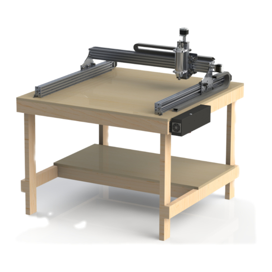
R7 Build Instructions
1. I
NTRODUCTION
The R7 is so named as this was the revision the SMW3D/ Hobby-Fab team released; this DIY CNC router
kit. The kit is fully open source. In addition, the kit was released in beta and all feedback taken to
improve build and functionality. Thank you for joining us on this journey. We truly hope this build will
help makers to achieve the satisfaction of creating a machine that will provide years of creativity with
their own two hands.
2. S
-
ET
UP
We would love for you to rip open this package like it's Christmas morning and you are eight years old
again. We must warn though, we have individually bagged the steps and they will match the below
inventory as well as the videos on YouTube on the SMW3D/Hobby-Fab page. The videos are labeled
R7v1, this means R7 video one, etc. Please DO NOT open every bag and dump the build on the table.
This will severely impact your build time and locating the proper parts for the steps. The build videos are
very outdated, they should only be used for reference.
We also advise finding a large, clean, flat surface to build your kit. The first few steps can certainly be
performed on a smaller surface however, as the build grows, you will need a four foot by four-foot area
flat surface. It is also advised that you lay out each step individually with all parts for the respective step.
Lastly, before starting the build, please note the BOM (Bill of Materials) is described below and two
columns are present after the item description. Please open each bag prior to build and count each item
and check it off the below list. If anything is missing, please contact us at contact@Hobby-Fab.com.
Performing this task now will prevent having to put off your build in the event we missed something.
Finally, please have fun and take your time. The build process will control all your cuts after, build it
once and build it right. The machine will provide years of great service.
Tools Required: (all should be locally available)
Metric allen wrench set
Soldering iron and solder
Metric tap set
8mm combination wrench
10mm combination wrench
Last updated: 08/13/20108
Additional Items Required
Bucket for water
Table
Computer
USB A to B cable
Square and level
Rev. 9
1
Advertisement

Summary of Contents for Hobby-Fab R7
- Page 1 YouTube on the SMW3D/Hobby-Fab page. The videos are labeled R7v1, this means R7 video one, etc. Please DO NOT open every bag and dump the build on the table. This will severely impact your build time and locating the proper parts for the steps. The build videos are very outdated, they should only be used for reference.
- Page 2 Step One: In the first step, you will be assembling the Y gantry plates. These plates will run on the side of the R7 as you are facing the machine. One notable change from the videos is the .2mm shims are no longer needed.
- Page 3 Last updated: 08/13/20108 Rev. 9 STEP 1 Qty. Smw3D Builder Y Gantry Plate LH Y Gantry Plate RH Large Xtreme Wheels Mini Delrin Wheels Adjustable Tension Anti-Backlash Nut 6mm Spacers 6mm Mini Eccentric Spacers 3mm Spacers M5x20 Bolt M5x25 Bolt...
- Page 4 Last updated: 08/13/20108 Rev. 9 Note, the large wheels get a shim from the wheel bag between the bearings but not between the eccentric spacer and bearing. The mini wheels get a shim from the wheel kit, between the bearings in the wheel and between the bearing and eccentric spacer.
- Page 5 Last updated: 08/13/20108 Rev. 9 The ACME block is installed by using two M5 x 20mm bolts, 3mm spacers, and two M5 nuts. Do not over-tighten these M5 x 20 bolts, it is possible to collapse the block. Simply snug up and use lock-tight. You can adjust the tension on the ACME block at this time if you so choose.
- Page 6 Last updated: 08/13/20108 Rev. 9 Limit switch and barrier block shown installed.
- Page 7 Last updated: 08/13/20108 Rev. 9 Step 2: Step two has us assembling the front X/Z gantry plate. While looking at the completed machine, this will be the front plate that holds the Z gantry and moves side to side in the X direction. Recall front to back is Y and up and down is Z.
- Page 8 Last updated: 08/13/20108 Rev. 9 Install the outer wheels and turn the eccentrics until the outer wheels touch the C-beam. The ACME block is installed in the same fashion as the first step.
- Page 9 Last updated: 08/13/20108 Rev. 9 Note limit switch on bottom of plate, these wires will remain loose till install.
- Page 10 Last updated: 08/13/20108 Rev. 9 Step 3: Step three will be the assembly of the rear X gantry plate. The same principles apply here. Use the reference wheels as a base and adjust the eccentrics to touch the inside of the sample beam (250mm length Z).
- Page 11 Last updated: 08/13/20108 Rev. 9 Notch in plate faces down. Limit switch on the left-hand side looking at the plate.
- Page 12 Last updated: 08/13/20108 Rev. 9 STEP 3 Qty. Smw3D Builder Rear XZ Gantry Plate Adjustable Tension Anti-Backlash Nut Mini Delrin Wheels 3mm spacers m5x20 m5x25 6mm Spacers 6mm mini eccentric spacers...
- Page 13 Last updated: 08/13/20108 Rev. 9 Step 4: Step four will be the joining of the front to the rear X gantry plates. When you have all the large wheels in place, apply a light amount of tension on the M5 nuts to hold everything together. Then, adjust the eccentrics so that the wheels are as far away from the center of the X axis as possible.
-
Page 14: Large Xtreme Wheels
Last updated: 08/13/20108 Rev. 9 STEP 4 Qty. Smw3d Builder Large Xtreme Wheels 9mm Spacers 6mm Mini Eccentric Spacers M5x60... - Page 15 Last updated: 08/13/20108 Rev. 9 Step 5: Step five we will mount the spindle to the Z gantry. The Z gantry will be the up and down axis of the machine. Note, the spindle clamp has been modified from the video. These spindle clamps are very fragile in the un-mounted state.
-
Page 16: Last Updated: 08/13/20108 Rev
Last updated: 08/13/20108 Rev. 9 Note, you can see both limit switches from the back view. The Z-limit wires can now be moved directly up (in relation to the picture) and through the notch in the rear plate and inserted into the Z-Axis screw terminals. - Page 17 Last updated: 08/13/20108 Rev. 9 Step 6: Step six we will build the X gantry. Note, on the X gantry there will be a piece of 1000mm length C-Beam and a 1000mm length 20x20 V-Slot. The V-slot will be the exact same length as one piece of C-Beam. The ends of the beam will be colored to indicate the matching C-Beam and 20x20 aluminum V-slot.
-
Page 18: Spacers
Last updated: 08/13/20108 Rev. 9 Qty. Smw3d Builder STEP 6 M5x15 M5x55 1.5in spacers 608ZZ Bearing 8mm lock collar 6.35x8 Coupler 1000mm Acme 1000mm 20x20 1000mm C Beam NEMA 23 2.8A Shim: 12.5x8x1.5... - Page 19 Last updated: 08/13/20108 Rev. 9...
- Page 20 Last updated: 08/13/20108 Rev. 9 Above, the motor installation is shown. Use the two longer bolts and spacers to attach the motor. Install the bearing, washer, and coupler as shown. Tighten all set screws on the coupler once the ACME is fully engaged.
- Page 21 Last updated: 08/13/20108 Rev. 9 The opposite side is constrained by the lock collar. In the step seven bag you will find an ACME nut plate. Use this to push the lock collar flush against the bearing and remove any slack from the drive. Excessive force is not needed.
-
Page 22: M5X20
Last updated: 08/13/20108 Rev. 9 Step 7: Step seven will be the build of the Y gantries. Your machine is really going to take shape after this step. This step is much of a repeat of the last, but we will be mounting end caps instead of Y gantry plates. Step 7 Smw3d Builder... - Page 23 Last updated: 08/13/20108 Rev. 9 Front machined end caps shown above. The L-shape should face the inside of the C of the beam. Rear machined plates have been modified, installation is the same but now has wiring blocks.
- Page 24 Last updated: 08/13/20108 Rev. 9 It is best to install the wood screws into the spoiler board near the last step when we can square the build. If you choose to install them now, thread the ACME in until the Y gantry plates are the same distance from the corner plates.
-
Page 25: M5X25
Last updated: 08/13/20108 Rev. 9 Step 8: We will assemble the full Z gantry in this step. Grab the Z gantry with the spindle and prepare to install this with the 250mm ACME. This axis is in compression versus the previous tension set-ups. Smw3d Builder Step 8... - Page 26 Last updated: 08/13/20108 Rev. 9 Thread the ACME through the anti-backlash nut, then slide the lock collar, bearing, and shim over the top. Attach one of the black plates on the top of the Z via the supplied M5 x 25mm bolts. Feed the Z gantry down through the wheels in the front of the X axis.
- Page 27 Last updated: 08/13/20108 Rev. 9...
- Page 28 Last updated: 08/13/20108 Rev. 9...
- Page 29 Run the cable chain down either the left or right side of the build. Mount one end to the y gantry plate. One plate will have a threaded hole in the middle of the hobby-fab logo, this is for the Y cable chain.
- Page 30 Last updated: 08/13/20108 Rev. 9...
- Page 31 Last updated: 08/13/20108 Rev. 9 Mount the X cable chain in the same method. Attach the upside-down end to the back of the Z gantry. There is a threaded hole in the upper corner of the rear plate. Use two 9mm spacers and the M5 x 25mm bolt, attach the other end to the top of the 20x20x1000mm v-slot with the drop-in tee-nut and M5x10mm bolt.
- Page 32 Last updated: 08/13/20108 Rev. 9...
- Page 33 Last updated: 08/13/20108 Rev. 9 Step 10: You have made it! The final step is the electronics of the kit. This video is rather short, so when you have questions hit the G+ group up and the team of builders will be happy to assist! The video is meant for builder that purchase the all in one control box.
- Page 34 Last updated: 08/13/20108 Rev. 9 Take time to familiarize yourself with this window. There are a lot of features here. If you want to jog the machine around go to the upper right-hand window, called Axes, click the down button and the box will expand.
- Page 35 Explore the machine, explore software, explore all that various things you can create. There is so much to learn and new opportunities around every corner when you can build the world around you. Join us and show off your build on the R7 Google Plus page. We look forward to the amazing things you will build!
- Page 36 It is suggested to keep fire suppression equipment close at hand and prepared for an emergency. SMW3D, Hobby-Fab, J-Tech and affiliated groups hold no liability to property, personal, or any other damage created from the use of this product. The purchase and use of this laser add on system is strictly the end user’s liability and responsibility to ensure safe use.
- Page 37 Last updated: 08/13/20108 Rev. 9 Shown above on the 400-watt spindle, 600w and 800w are identical. These holes should center the laser in the Y plane with the spindle center. Open the laser package and look for a small bracket that will fix a fan to the back of the diode laser.
- Page 38 Last updated: 08/13/20108 Rev. 9 Install the laser diode with this bracket. The laser should face downwards with the fan mounted on the bracket with the Sunon logo facing the diode. It is advised to install the laser M3 bolts with blue thread lock.
- Page 39 Last updated: 08/13/20108 Rev. 9 The laser diode will connect to the driver board on the H3 header and the fan will connect to the fan header.
- Page 40 Last updated: 08/13/20108 Rev. 9 1 Shown uninstalled for relation Next connection will be the PWM signal. Regardless of the GRBL controller sent we will utilize the PWM + and – signals to control the laser power.
- Page 41 Last updated: 08/13/20108 Rev. 9 Connect the bare ended wire with the molex connector on the opposite side next to the laser connector, connect the other end to the PWM positive and negative connections on the board. Polarity matters. On the all in one controller the accessory port, yellow is PWM +, blue is PWM -.
- Page 42 Last updated: 08/13/20108 Rev. 9 Use: When the laser driver board is powered for the first time, every use, the reset button must be pressed. Insert the safety key, turn on the power and press the rest button. The fans should both come on along with a green LED indicating the driver board is ready for use.
- Page 43 0 for maximum efficiency. The number one mistake we make here is forgetting to turn the machine back to router mode. After laser operations recall to set $32=0. Any questions please do not hesitate to contact us we will happy to assist. Contact@hobby-fab.com...
- Page 44 OUTLET. The box is internally grounded and fused for both AC and DC but your safety is top priority, a damaged box should not be used. SMW3D, Hobby-Fab and related affiliates hold no responsibility for damage to equipment or persons by using this product. Be safe, be smart, build! CARE: The control box is made of cold rolled steel and the early units have a black oxide coating.
- Page 45 Last updated: 08/13/20108 Rev. 9 Connections: Step 1: Connect all stepper motors to the X, Y, (if using a gantry style machine Y2) and Z. The 6 pin connectors are labelled below. Looking at the face of the box the connections are, from left to right: Accessories : Black/ White = Z probe Yellow/Blue = (+/-) PWM...
- Page 46 Last updated: 08/13/20108 Rev. 9 Step 2: Make sure the E-Stop is “out” this allows power to the control board. Step 3: Plug in a USB style Mouse and Keyboard to either USB port on the front. Step 4: Plug an HDMI monitor into the port on the face. Step 5: Plug the 110VAC cable into the fused connection on the far left.
- Page 47 Last updated: 08/13/20108 Rev. 9 USE: Every control box is tested prior to shipment. Based on your machine some changes may be required prior to use. E-stopping the box kills power to the motors, but does not remove power to the program. In the event of an issue, one should be able to retain the current program and restart after homing.
-
Page 48: Setting Value
Last updated: 08/13/20108 Rev. 9 Setting Value Mask Invert X Invert Y Invert Z 00000000 00000001 00000010 00000011 00000100 00000101 00000110 00000111 For instance, when you typed $$ and hit enter, and your current $3=1 and your Z was going the wrong direction, try $3=6 hit enter. - Page 49 Last updated: 08/13/20108 Rev. 9 Please email or call if there are any issues we are happy to assist. contact@hobby-fab.com or 346-333-6500.
Need help?
Do you have a question about the R7 and is the answer not in the manual?
Questions and answers