Table of Contents
Advertisement
Quick Links
Advertisement
Table of Contents

Related Manuals for Jet JDP-20EVS


Summary of Contents for Jet JDP-20EVS
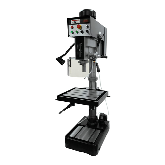
- Page 1 This .pdf document is bookmarked Operating Instructions and Parts Manual Variable Speed Drill Press Model JDP-20EVS 427 New Sanford Road LaVergne, Tennessee 37086 Part No. M-354210 Ph.: 800-274-6848 Revision K 01/2016 www.jettools.com Copyright © 2016 JET...
-
Page 2: Warranty And Service
JET sells through distributors only. The specifications listed in JET printed materials and on official JET website are given as general information and are not binding. JET reserves the right to effect at any time, without prior notice, those alterations to parts, fittings, and accessory equipment which they may deem necessary for any reason ®... -
Page 3: Table Of Contents
Table of Contents ..............................3 Introduction ................................5 Specifications ................................ 5 Unpacking and Clean-Up ............................6 Lifting the JDP-20EVS ............................6 Installation ................................6 Electrical Connections ............................7 Raising the Head ............................... 8 ... - Page 4 For your own safety, read the owner’s manual before operating the drill press. This drill press is designed and intended for use by properly trained and experienced personnel only. If you are not familiar with the proper and safe operation of a drill press, do not use until proper training and knowledge has been obtained.
-
Page 5: Introduction
If there are any questions or comments, please contact either your local supplier or JET. JET can also be reached at our web site: www.jettools.com. -
Page 6: Unpacking And Clean-Up
1. Make sure the two head locking bolts (refer to A, Fig. 4) are tight prior to lifting. 4. Position the JDP-20EVS next to the area that will be used for the machine. 5. The “Lifting Point” should be used to raise the drill press off of the shipping pallet. -
Page 7: Electrical Connections
Failure to comply may result in serious injury. The motor for the JDP-20EVS/230 is rated at 2HP, 3PH 230V only. The machine can also be run on 1-Phase power by hooking up the ground, L1 and L2 wires, as explained below. -
Page 8: Raising The Head
Raising the Head The drill press head is lowered on the column for crating and transportation. Before operating the drill press, the head will need to be raised to the operational level. To raise the head: 1. Loosen the two head locking bolts (A, Figure 4) by turning counterclockwise. -
Page 9: Adjustments
Adjustments Raising the Rack Some drilling operations will require the table to be moved closer to the spindle than the rack will allow as set by the factory. To raise the rack: 1. Tighten the table lock handle (A, Fig. 7). 2. - Page 10 NOTE: The Electronic Variable Speed unit is designed to shut down, to prevent harm to the system, in the event of overloading the spindle. Make sure the Speed Control Knob and the High- Low Handle are in the matching ranges for the work being done.
- Page 11 Installing Tools into the Spindle Bore 1. Disconnect the machine from the power source. 2. Make sure the spindle bore and the tool are clean and free of oil. 3. Place a protective piece of scrap wood on the table. 4.
-
Page 12: Drill Speed Chart
Drill Speed Chart There are many variables when determining what RPM to use. Use the following drill speed chart to choose the approximate drill speed for the size bit, and type of material to be drilled. The chart is a general reference for a 90°... -
Page 13: Top Head Assembly
Top Head Assembly... -
Page 14: Parts List: Top Head Assembly
Parts List: Top Head Assembly Index No. Part No. Description Size 1 ....20EVS-T01G ..... Head Body ..................... 1 2 ....20EVS-T02....Sight Glass ....................1 3 ....BB-6202Z ....Ball Bearing ............. 6202Z ......1 4 ....20EVS-T04....C-Clip ............... S31........ 1 5 .... - Page 15 Index No. Part No. Description Size 55 ....TS-1515031 ....Hex Socket Cap Screw ..........M8x25 ......4 94 ....20EVS-T94....Set Screw ..............1/4”x1/4” ......4 95 ....20EVS-T95....Cross Head Screw ........... M3x16 ......4 96 ....20EVS-T96....Micro Switch ....................2 97 ....
-
Page 16: Head Assembly
Head Assembly... -
Page 17: Parts List: Head Assembly
Parts List: Head Assembly Index No. Part No. Description Size 1 ....20EVS-T01G ..... Head Body ..................... 1 2 ....20EVS-H2 ....Hex Head Bolt............1/2”x4-1/2”..... 2 2-1 ..... 20EVS-H2-1 ....Spring ......................2 3 ....20EVS-H3 ....Left Lock Sleeve .................... 2 4 .... -
Page 18: Exploded View - Safety Shield Assembly (All Models)
Exploded View – Safety Shield Assembly (All Models) Parts List – Safety Shield Assembly (All Models) Index No. Part No. Description Size ....32106A ....Safety Shield Assembly (#1 thru 16) ............1 ....6293347....Spring Pin............3x16 ......1 2 ....32106A-2 ....Support Bracket Bar ................1 3 .... -
Page 19: Control Panel Assembly
Control Panel Assembly... -
Page 20: Parts List: Control Panel Assembly
Parts List: Control Panel Assembly Index No. Part No. Description Size 56 ....20EVS-T56....Speed Control Knob ..................1 57 ....20EVS-T57....Drill/Tap Switch ....................1 58 ....20EVS-T58....Pump Switch ....................1 59 ....20EVS-T59....Reverse Switch ....................1 60 .... -
Page 21: Electrical Cabinet Assembly
Electrical Cabinet Assembly... -
Page 22: Parts List: Electrical Cabinet Assembly
Parts List: Electrical Cabinet Assembly Index No. Part No. Description Size 70 ....20EVS-T70....Electric Control Box w/Door and Latch ............1 (serial no. 3040097 and higher on the 460V model) 70-1 ... 20EVS-T70-1 .... Brass Plate ....................1 70-2 ... -
Page 23: Column/Table/Base Assembly
Column/Table/Base Assembly... -
Page 24: Parts List: Column/Table/Base Assembly
Parts List: Column/Table/Base Assembly Index No. Part No. Description Size 1 ....20EVS-C1 ....Coolant Base ..........1 (previous to serial no. 7090372) ....20EVS-C1N....Coolant Base (serial no. 7090372 and higher) ..........1 1-1 ..... TS-0720111 ....Lock Washer ............1/2” ........ 6 1-2 ..... - Page 25 Index No. Part No. Description Size 58 ....20EVS-C58 ....Pan Head Screw .................... 1 59 ....20EVS-C59 ....Plug................3/8”PT ......1 60 ....TS-1522021 ....Socket Set Screw ............ M5x8 ......2 61 ....20EVS-TRM ....Table Raising Mechanism Assembly ............. 1 ....
-
Page 26: Coolant Pump Assembly
Coolant Pump Assembly Index No. Part No. Description Size 1 ....20EVS-C1 ....Coolant Base ....................1 2 ....20EVS-C2 ....Cover ......................1 3 ....20EVS-CP3PH ..Coolant Pump ............1/8 HP, 230V, 3 Ph ..1 .... -
Page 27: Electrical Cabinet
Electrical Cabinet Index No. Part No. Description Size Q ....20EVS-T91....Safety Switch Assembly .......... 500Vac,16A ....1 F1 ....20EVS-T80....Fuse ................. 0.5A....... 1 F2 ....20EVS-T80....Fuse ................. 0.5A....... 1 F3 ....20EVS-T80-1 .... Fuse ................. 2A........1 KM1 ... -
Page 28: Wiring Diagram - 460 Volt, 3 Phase
Wiring Diagram – 460 Volt, 3 Phase... -
Page 29: Wiring Diagram - 230 Volt, 1 & 3 Phase
Wiring Diagram – 230 Volt, 1 & 3 Phase... - Page 30 This page intentionally left blank.
- Page 31 This page intentionally left blank.
- Page 32 427 New Sanford Road LaVergne, Tennessee 37086 Phone: 800-274-6848 www.jettools.com...
Need help?
Do you have a question about the JDP-20EVS and is the answer not in the manual?
Questions and answers