
Related Manuals for Rain Bird IQ


Summary of Contents for Rain Bird IQ
- Page 1 Network Communication Cartridge (IQ-NCC) ™ Installation & User Guide for the IQ ™ Central Control System...
- Page 2 Symbol alerts the user to the presence of WARNING: electricity or electromagnetic energy which may constitute Or contact Rain Bird Global Support Plan: a risk of electric shock, radiation exposure or other hazard. U.S. and Canada Symbol alerts the user to important instructions...
-
Page 3: Table Of Contents
IQ Port Cable or Antenna ........... 4 LED Indicators ................26 Connection Module (CM) ........... 4 Table 1 - IQ Port LED Indicators .........27 Connection Module (CM) Port Cable......4 Table 2 - CM Port LED Indicators ......28 Radio Modem Cable ............. 4 Table 3 - Radio Port LED Indicators ......28... - Page 4 Connection Modules .......... 36 Connection Module Options ..........36 Base Module ...............36 Flow Smart Module ............36 IQ Connection Module ..........37 IQ Flow Smart Connection Module ......37 Connection Module Installation ........38 Connect IQ-CM Grounding Wire ......40 SIM Card Installation ......... 41 IQ Network Communication Cartridge...
-
Page 5: Introduction
IQ Central Control System. For more than seven decades, multiple ESP-LXME and ESP-LXD Satellite Controllers from a Rain Bird has led the irrigation industry in meeting all of your single personal computer. water management needs by providing the highest quality IQ™... -
Page 6: Types Of Iq ™ Satellite Controllers
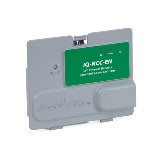
Phone Network Communication Cartridge (IQ-NCC-PH) Direct Satellites communicate with the IQ Central Computer Ethernet Network Communication Cartridge (IQ-NCC-EN) through a wired or wireless connection to an IQ-NCC. Direct Satellites do not communicate with other Satellites. GPRS/Cellular Network Communication Cartridge (IQ-NCC-GP) - Page 7 Figure 1 - IQ™ Network Communication Cartridge (IQ-NCC-GP shown) IQ Network Communication Cartridge...
-
Page 8: Installation
Network Communication ™ Radio Modem Cable Cartridge Components A radio modem can also be connected to the IQ-NCC to provide wireless radio communication between Server and Network Communication Cartridge Client Satellites on the IQNet. Five types of cartridges are available to communicate with... -
Page 9: Figure 2 - Installation Overview
ESP-LX Controller Front Panel IQ Port Cable (or Antenna) IQ Network Communication Ground Wire (to earth ground) Cartridge (IQ-NCC-EN shown) IQNet PE Communication Connection Module (CM) Cable Cable to other Satellites (CM Y-Cable shown) Connection Module a. To IQNet Radio Modem (FSCM-LXME shown) b. -
Page 10: Box Contents
Box Contents 3. IQ Computer Connection Cable or Antenna (ONE of the following): The following components are included with each IQ-NCC RS-232 External Modem Cable (IQ-NCC-RS) and are required for installation. RJ-11 Phone Cord (IQ-NCC-PH) NOTE: If anything is missing, please contact your distributor before proceeding. - Page 11 CM Y-Cable (black) RJ-11 Phone Cord (Silver) CM Straight Cable (black) RJ-45 Ethernet Cable (Green) GPRS/Cellular Internal IQ Network Antenna (Gold) Communication Cartridge (IQ-NCC) WiFi Internal Antenna (Gold) Installation & User Guide Figure 3 - Box Contents IQ Network Communication Cartridge...
-
Page 12: Cartridge Installation
Cartridge Installation Pull the handle towards you and swing it to the left. This section provides steps required to install an IQ-NCC and connect the required cables. The steps apply to all types of cartridges with any differences explained separately. -
Page 13: Remove The Communication Cable Knock-Out
Remove the Communication Cable Knock-out Locate the IQ Port communication cable knock-out on the bottom left of the controller case, next to the transformer junction box. If a CM connection module will be installed for IQNet communication, locate the rear knock-out for the IQNet communication cable. -
Page 14: Install An External Antenna For Lxmm
Using a power drill and 5/8” (16 mm) drill bit, drill a hole through the “dimple” on the top right of the LXMM metal case. CAUTION: always wear eye protection when using tools or power equipment. IQ Network Communication Cartridge... - Page 15 20 cm from all persons and must not be located or of the metal case and the controller. Set the antenna operating in conjunction with any other antenna or into the hole and secure from the inside as shown, transmitter. using the washers and nut provided. IQ Network Communication Cartridge...
-
Page 16: Install The Cartridge
If the satellite is a Server or Client that will use a radio Connect the IQ Port cable or antenna to the cartridge module for wireless communications AND a wired (see Fig. 4). This cable or antenna provides the connection (IQNet PE Communication Cable) communication to the IQ computer. - Page 17 RJ-11 Phone Cord (Silver) IQ Network Communication RJ-45 Ethernet Cable (Green) Cartridge (IQ-NCC) GPRS Cellular Internal Antenna (Gold) Align Arrows on Cable and WiFi Internal Antenna (Gold) Housing for Correct Fitting Figure 4 - Installation/ Cable Options IQ Network Communication Cartridge...
- Page 18 Route the small end of the into the hinge openings at the bottom of the cartridge cable through the bottom of the knockout first, then bay. Then gently swing the IQ-NCC up into place, connect to the CM Port. snapping the top latch.
-
Page 19: Complete Cable Connections
If installing the NCC-PH cartridge, connect the Green and yellow ground wire to the grounding post on the Route all cables from the cartridge through the channel left side of the controller backplane. in back of the front panel. IQ Network Communication Cartridge... - Page 20 IQ software package and sold separately to make the connection to the IQ computer or IQSSRADIO. To establish a wired connection with another satellite,...
- Page 21 CAUTION: Ensure that all installed cables inside the satellite do not contact the transformer directly, as heat from the transformer may cause damage to a cable. FSCM shown Secure all cables inside the controller and close the front panel. IQ Network Communication Cartridge...
-
Page 22: Internal Antenna Installation
CAUTION: Take special care the first time when placing the antenna. Once installed it cannot be easily removed again. GPRS Cellular Internal Antenna Installation NOTE: Internal antennas must be installed in a vertical position as shown to ensure maximum signal strength. IQ Network Communication Cartridge... - Page 23 WiFi Antenna Back-plane WiFi Internal Antenna Installation IQ Network Communication Cartridge...
-
Page 24: Iq-Ncc Configuration
Turn the controller dial to is displayed. Use + or - to select screen is displayed; press Next. ETM/IQ SETTINGS. Direct; press Next. For RS Only: use + or - to choose an IQ Port option, then press Next. IQ Network Communication Cartridge... - Page 25 Cartridge NOTE: has three options, External Modem, IQ Direct Connect, and IQSSRADIO. All other cartridges have only one option, either Phone, GPRS/Cellular, Ethernet, or WiFi modem depending on the cartridge that is installed. The following message will be displayed. Press Dismiss to exit screen.
-
Page 26: Server Satellite Setup Wizard
The Setup – Satellite IQ Port is displayed. Use + or - to select screen is displayed; press Next. Server; press Next. For RS Only: use + or - to choose an IQ Port option, then press Next. IQ Network Communication Cartridge... - Page 27 NOTE: If an IQ-FSCM-LXME NOTE: has three options, External for connection to a radio modem or an IQ-CM-LXD connection Modem, IQ Direct Connect, and for wireless communication with module is installed for wired IQSSRADIO. All other cartridges other satellites, choose Radio...
-
Page 28: Client Satellite Setup Wizard
Client Satellite Setup Wizard The IQ Settings main menu is The Setup – Satellite Address displayed. Use the UP or DOWN screen is displayed. Use + or - Follow these steps to configure a arrows to select Setup Wizard; to select a unique address from controller as a Client Satellite: press Next. -
Page 29: Ncc Configurator Software
Module after installation and configuration Installed. of the IQ-NCC cartridge is complete. The Setup – Satellite CM Port Software configuration is only required screen is displayed. Use + or - The Setup – CM Port Termination for Direct and Server Satellites. Consult to select a CM Port option (No screen is displayed. -
Page 30: Operation
Reset button restarts internal programming and re-enables communications with the IQ Central Computer without affecting configuration settings. LED Indicators The three LED lights on the front of each cartridge indicate the status of each communication port on any satellite controller. - Page 31 Blinking Red/Yellow Reflash or Reset Reflash or Reset Reflash or Reset Reflash or Reset Reflash or Reset (sync all 3 LED’s) Table 1 - IQ Port LED Indicators IQ Network Communication Cartridge...
- Page 32 Client Satellites with both an IQNET Radio and CM Connection Module installed will continue to flash Connection Module installed will continue to flash green as it searches for Client Satellites. green as it searches for Client Satellites. IQ Network Communication Cartridge...
-
Page 33: Status Menu
Status Menu Direct Satellite Controllers The IQ Settings main menu is displayed. Use the UP or DOWN RS-232, Phone or Ethernet The Status Menu is used to display the arrows to select Status; press To display the status of Direct status of each communication port on Next. -
Page 34: Gprs Or Wifi
Direct Satellite Controllers The IQ Settings main menu is The Signal Strength screen is displayed. Use the UP or DOWN displayed. The signal strength GPRS or WiFi arrows to select Status; press between the satellite and the To display the status of Direct Next. -
Page 35: Server Satellite Controllers
Server Satellite Controllers The IQ Settings main menu is IQNet Ping screen displayed. Use the UP or DOWN displayed. Use the + and - RS-232, Phone or Ethernet arrows to select Status; press buttons to select any Client To display the status of Server Next address. -
Page 36: Gprs Or Wifi
Server Satellite Controllers The IQ Settings main menu is The Signal Strength screen is displayed. Use the UP or DOWN displayed. The signal strength GPRS or WiFi arrows to select Status; press between the satellite and the To display the status of Server Next. -
Page 37: Client Satellite Controllers
IQNet Ping screen Client Satellite Controllers The IQ Settings main menu is displayed. Use the + and - displayed. Use the UP or DOWN To display the status of Client buttons to select any Client arrows to select Status; press... -
Page 38: Iqnet Alarms Menu
IQNet Alarms Menu The IQ Settings main menu is If there is a communication displayed. Use the UP or DOWN failure between Server The IQNet Alarms Menu is used to arrows to select IQNet Alarms; Satellite and Client Satellites, display... - Page 39 IQNet Alarm screen will be displayed on the Client Satellite. Use the UP or DOWN arrows to view other alarms. 03:45AM 05 JAN 2010 On either IQNet Alarm screen, press Clear to clear all alarms. Press Yes to confirm. IQ Network Communication Cartridge...
-
Page 40: Appendix
Module used in an ESP-LXME controller There are four different types of ESP-LXME controller. This module can can be used with an IQ-NCC when connection modules that may be be used with an IQ-NCC when wired wired communications with other... -
Page 41: Iq Connection Module
IQ Connection Module IQ Flow Smart Connection Module NOTE: See the ESP-LXME Con- troller manual for instructions If wired communications (IQNet PE If wired communications (IQNet PE on configuring the Flow Smart Communication Cable) is required Communication Cable) is required Module. -
Page 42: Connection Module Installation
Connection Module Installation Orient the connector on the bottom of the IQ-FSCM- LXME or IQ-CM-LXD module with the connection Follow these steps if a connection module is required for socket on the satellite backplane. IQNet wired communications: Carefully fasten the module onto the satellite To remove an existing base module, press in on the backplane, pressing firmly until it snaps into place. - Page 43 Connect the Green and yellow ground wire to the grounding post on the left side of the satellite backplane. NOTE: If the ground wire from an IQ-NCC-PH cartridge has been previously installed on the grounding post, disconnect the wire. Connect the connection module...
-
Page 44: Connect Iq-Cm Grounding Wire
Connect IQ-CM Grounding Wire An additional ground wire is required if you’re installing either an IQ-CM-LXD or IQ-CM-LXME connection module. Attach one end of the grounding wire to Earth ground (electrical ground, ground rod or ground plate). Route the grounding wire through the knock-out on the bottom of the controller. -
Page 45: Sim Card Installation
Orient the SIM card to match the image of the SIM card as displayed molded on the cartridge (with the “cut- The GPRS/Cellular Network Communication Cartridge (IQ- corner” on top and to left as shown). NCC-GP) requires a SIM card to establish a connection with Install the SIM card in the slot. - Page 46 FCC regulations, the user must use shielded cables and connectors and install them per instructions. network interface when servicing. WARNING: Changes or modifications not expressly approved by Rain Bird Corporation could void the user’s authority to operate the equipment.
- Page 47 The wireless carrier will require the device’s IMEI (International Mobile Equipment Identity) number. This IMEI number is printed on the label on the backside of the modem cartridge. Complies with 47 CFR Part 68. Reg. No: US:AU7MM01BMT5692SMI REN: 0.1B...
- Page 48 RAIN BIRD CORPORATION 6991 E. Southpoint Road Tucson, AZ 85756 Copyright © 2010 by Rain Bird Corporation. All rights reserved. This material may not be published or reproduced without permission. “Rain Bird” and “IQ Central Control System” are registered trademarks of Rain Bird Corporation.
Need help?
Do you have a question about the IQ and is the answer not in the manual?
Questions and answers