
Related Manuals for Leadshine Technology Co. 3DM580


Summary of Contents for Leadshine Technology Co. 3DM580
- Page 1 User’s Manual 3DM580 Fully Digital Three Phase Stepping Driver Revision 1.0 ©2016 All Rights Reserved ...
- Page 2 The content in this manual has been carefully prepared and is believed to be accurate, but no responsibility is assumed for inaccuracies. Leadshine reserves the right to make changes without further notice to any products herein to improve reliability, function or design. Leadshine does not assume any liability arising out of the application or use of any product or circuit described herein;...
-
Page 3: Table Of Contents
Contents Table of Contents 1. Introduction, Features and Applications..............1 Introduction......................1 Features........................1 Applications......................1 2. Specifications.......................2 Electrical Specifications..................2 Mechanical Specifications..................2 Elimination of Heat....................2 Operating Environment and other Specifications........... 3 3. Pin Assignment and Description................. 3 Connector P1 Configurations.................. 3 Selecting Active Pulse Edge and Control Signal Mode..........4 Connector P2 Configurations.................. - Page 4 Contents Over-voltage Protection.................11 Phase Error Protection...................11 Protection Indications..................11 12. Frequently Asked Questions..................11 Problem Symptoms and Possible Causes..............12 APPENDIX........................13 Twelve Month Limited Warranty................13 Exclusions......................13 Obtaining Warranty Service.................. 13 Warranty Limitations.....................13 Contact Us........................14...
-
Page 5: Introduction, Features And Applications
1. Introduction, Features and Applications Introduction The 3DM580 is a versatility fully digital stepping driver based on a DSP with advanced control algorithm. The 3DM580 is the next generation of digital stepping motor controls. It brings a unique level of system smoothness, providing optimum torque and nulls mid-range instability. -
Page 6: Specifications
3DM580 Digital Stepping Driver Manual V1.1 2. Specifications Electrical Specifications (T = 25℃/77℉) 3DM580 Parameters Typical Unit Output current 8.0 (5.7 RMS) Supply voltage Logic signal current Pulse input frequency Isolation resistance MΩ Mechanical Specifications (unit: mm [inch], 1 inch = 25.4... -
Page 7: Operating Environment And Other Specifications
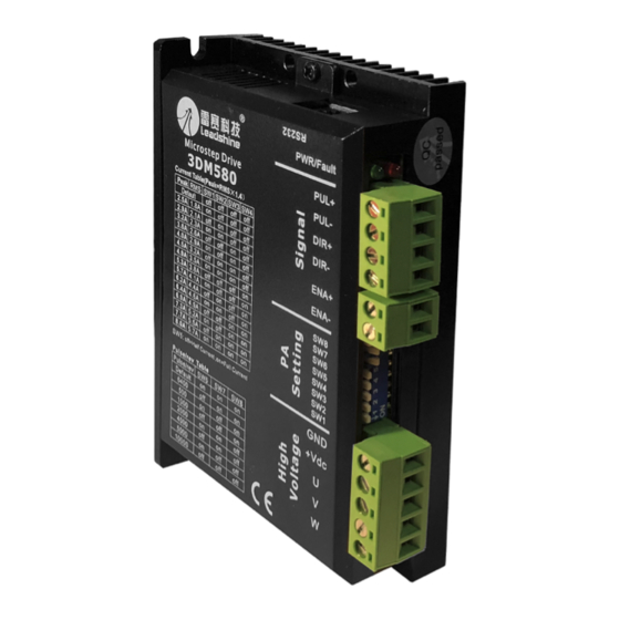
Approx. 270g (9.5oz) 3. Pin Assignment and Description The 3DM580 has two connectors, connector P1 for control signals connections, and connector P2 for power and motor connections. The following tables are brief descriptions of the two connectors. More detailed descriptions of the pins and related issues are presented in section 4, 5, 9. -
Page 8: Selecting Active Pulse Edge And Control Signal Mode
The 3DM580 can accept differential and single-ended inputs (including open-collector and PNP output). The 3DM580 has 3 optically isolated logic inputs which are located on connector P1 to accept line driver control signals. These inputs are isolated to minimize or eliminate electrical noises coupled onto the drive control signals. -
Page 9: Connecting The Motor
Figure 3: Connection to PNP signal (common-cathode) 5. Connecting the Motor The 3DM580 can drive any 3 lead or 6 lead three phase hybrid stepping motors. The connection between the driver and 3-phase stepping motors includes two different kinds of connections, namely delta-connection and star-connection. -
Page 10: Regulated Or Unregulated Power Supply
Instead, please connect them to power supply separately. Selecting Supply Voltage The power MOSFETS inside the 3DM580 can actually operate within +20 ~ +50VDC, including power input fluctuation and back EMF voltage generated by motor coils during motor shaft deceleration. -
Page 11: Microstep Resolution Selection
3DM580 Digital Stepping Driver Manual V1.1 51,200 steps/rev and the latter can be set from 1.0A to 8.0A. See more information about Microstep Resolution and Output Current Setting in Section table. However, when it’s not in configured mode, this driver uses an 8-bit DIP switch to set microstep... -
Page 12: Dynamic Current Setting
3DM580 Digital Stepping Driver Manual V1.1 7.7A 5.5A 8.0A 5.7A For a given motor, higher driver current will make the motor to output more torque, but at the same time causes more heating in the motor and driver. Therefore, output current is generally set to be such that the motor will not overheat for long time operation. -
Page 13: Wiring Notes
3DM580 Digital Stepping Driver Manual V1.1 The current automatically reduced to 50% of the selected dynamic current one second after the last pulse. Theoretically, this will reduce motor heating to 25% (due to P=I *R) of the original value. If the application needs a different standstill current, please contact Leadshine. -
Page 14: Sequence Chart Of Control Signals
Low level width not less than 2.5s. 11. Protection Functions To improve reliability, the driver incorporates some built-in protection functions. The 3DM580 uses one RED LED to indicate what protection has been activated. The periodic time of RED is 3 s (seconds), and how many times the RED turns on indicates what protection has been activated. -
Page 15: Over-Voltage Protection
3DM580 Digital Stepping Driver Manual V1.1 Over-voltage Protection When power supply voltage exceeds 62±1 VDC, protection will be activated and RED LED will turn on twice within each periodic time (3 s). Short-Circuit Protection Motor power lines wrong & not connected will activate this protection. RED LED will turn on four times within each periodic time (3 s). -
Page 16: Problem Symptoms And Possible Causes
3DM580 Digital Stepping Driver Manual V1.1 Problem Symptoms and Possible Causes Symptoms Possible Problems No power Microstep resolution setting is wrong Motor is not rotating DIP switch current setting is wrong Fault condition exists The driver is disabled Motor rotates in the wrong direction... -
Page 17: Appendix
3DM580 Digital Stepping Driver Manual V1.1 APPENDIX Twelve Month Limited Warranty Leadshine Technology Co., Ltd. warrants its products against defects in materials and workmanship for a period of 12 months from shipment out of factory. During the warranty period, Leadshine will either, at its option, repair or replace products which proved to be defective. -
Page 18: Contact Us
3DM580 Digital Stepping Driver Manual V1.1 Contact Us (headquarters) Leadshine America Inc. Leadshine Technology Co., Ltd Address: 26050 Towne Centre Dr. Address: Floor 11, Block A3, Nanshan iPark Foothill Ranch, CA 92610 1001 Xueyuan Avenue Nanshan District Shenzhen, Guangdong, 518055...
Need help?
Do you have a question about the 3DM580 and is the answer not in the manual?
Questions and answers