Table of Contents
Advertisement
Quick Links
Leadshine Technology Co., Ltd
Address: Floor 11, Block A3, iPark
1001 Xueyuan Avenue
Shenzhen, Guangdong 518055
China
Tel:
86-400-885-5521
Fax:
86-755-2640-2718
Web:
www.leadshine.com
Sales:
sales@leadshine.com
Support:
tech@leadshine.com
User Manual
CS-D508
Closed Loop Stepper Drive
Revision 3.1
©2018 Leadshine Technology Co., Ltd.
(Headquarters)
CS-D508 Closed Loop Stepper Drive User Manual Version 3.1
Leadshine America, Inc.
Address: 26050 Towne Centre Dr.
Foothill Ranch, CA 926
USA
Tel:
1-949-608-7270
Fax:
1-949-608-7298
Web:
www.leadshineusa.com
Sales:
sales@leadshineusa.com
Support:
support@leadshineusa.com
Advertisement
Table of Contents

Related Manuals for Leadshine Technology Co. CS-D508


Summary of Contents for Leadshine Technology Co. CS-D508
- Page 1 CS-D508 Closed Loop Stepper Drive User Manual Version 3.1 User Manual CS-D508 Closed Loop Stepper Drive Revision 3.1 ©2018 Leadshine Technology Co., Ltd. Leadshine Technology Co., Ltd (Headquarters) Leadshine America, Inc. Address: Floor 11, Block A3, iPark Address: 26050 Towne Centre Dr.
- Page 2 CS-D508 Closed Loop Stepper Drive User Manual Version 3.1 Notice Read this manual carefully before any assembling and using. Incorrect handling of products in this manual can result in injury and damage to persons and machinery. Strictly adhere to the technical information regarding installation requirements.
-
Page 3: Table Of Contents
CS-D508 Closed Loop Stepper Drive User Manual Version 3.1 Table of Content 1. Introduction.................................. 1 1.1 Features ................................1 1.2 Applications ................................. 1 2. Specifications ................................2 2.1 Electrical Specifications ............................2 2.2 Environment ................................ 2 2.3 Mechanical Specifications ........................... 3 2.4 Heat Dissipation.............................. - Page 4 11. Accessories ................................13 12. Troubleshooting ............................... 14 13. Warranty .................................. 16 Appendix A. Leadshine CS-D508 Compatible Stepper Motors ................17 Appendix B. Leadshine CS-D508 Compatible Power Supplies ................18 Appendix C. Powering a Third Party Motor with CS-D508 ................... 19...
-
Page 5: Introduction
CS-D508 Closed Loop Stepper Drive User Manual Version 3.1 1. Introduction Leadshine CS-D508 is a closed loop stepper drive designed to solve the loss of step problem in open loop stepper control systems, thus increase system reliability at minimal cost increase. It implements advanced control algorithm of Leadshine based on its tens of years’... -
Page 6: Specifications
CS-D508 Closed Loop Stepper Drive User Manual Version 3.1 2. Specifications 2.1 Electrical Specifications Parameters Typical Unit Output Current 8.0(Peak) Operating Voltage 24, 36, 48 Logic signal current Pulse input frequency μS Minimal pulse width μS Minimal direction setup MΩ... -
Page 7: Mechanical Specifications
It is recommended to mount the drive vertically to maximize heat dissipation. Mount a cooling fan nearby if necessary. If multiple CS-D508 drives are installed, it is suggested to keep a minimal 30mm (12 inches) between two of them. Page | 3... -
Page 8: Connector P1 - Control And Digital Output Connections
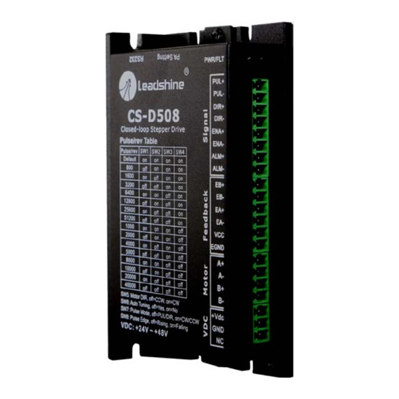
CS-D508 Closed Loop Stepper Drive User Manual Version 3.1 3. Connections and LED Indication A CS-D508 closed loop stepper drive has 5 connection blocks from P1 to P5 (see figure 2). Figure 2: CS-D508 connectors 3.1 Connector P1 – Control and Digital Output Connections 3.1.1 Pin Assignments of P1... - Page 9 Fault Output The FAULT output is the default configuration. It signals a fault condition of CS-D508, including over-voltage, over-current, or position following error. This output can be used to drive devices such as a relay, a LED, etc.; or as an input signal for a PLC or I/O devices.
-
Page 10: Typical Control And Fault Output Connections
3.1.2 Typical Control and Fault Output Connections The CS-D508 can accept differential and single-ended control signal inputs (open-collector and PNP output). A CS- D508 has 3 optically isolated control inputs, PUL, DIR, and ENA. Refer to the following two figures for connections of open-collector and PNP signals. -
Page 11: Connector P2 - Encoder Connection
CS-D508 Closed Loop Stepper Drive User Manual Version 3.1 (Common-cathode) (Common-anode) 3.2 Connector P2 - Encoder Connection The P2 connector in Figure 2 is for encoder signal connection. Refer to the following table for details. Drive Pin Name Description Encoder B+ input connection... -
Page 12: Connector P5 - Rs232 Connection
3.6 LED Light Indication There are two LED lights for CS-D508, one red and one green. The GREEN one is the power indicator which will be always on generally. The RED one is a protection indicator. It is off always when a CS-D508 operates normally, but will flash 1, 2 or 7 times in a 5-second period when error protection is enabled. -
Page 13: Regulated Or Unregulated Power Supply
5.2 Power Supply Sharing Multiple CS-D508 drives can share one power supply to save space and reduce cost, if that power supply has enough power capacity. To avoid cross interference, connect each stepper drive directly to the shared power supply separately. -
Page 14: Microstep Resolution (Sw1-Sw4)
CS-D508 Closed Loop Stepper Drive User Manual Version 3.1 Figure 5 DIP switch Setting 6.1 Microstep Resolution (SW1-SW4) Microstep resolution is set by SW1, 2, 3, 4 of the DIP switches as shown in the following table: Steps/Revolution Software Configured (Defaulted to 1600) -
Page 15: Other Dip Switch Settings (Sw5-Sw8)
Pulse Edge Falling Rising 7. Typical Connection A complete closed loop stepper system should include a stepper motor with encoder, CS-D508 drive, power supply and controller (pulse generator). A typical connection is illustrated in figure 6. Encoder Signal Controller CS-D508... -
Page 16: Fault Protections
CS-D508 Closed Loop Stepper Drive User Manual Version 3.1 Figure 7: Sequence chart of control signals Remark: t1: ENA must be ahead of DIR by at least 500ms. Usually, ENA+ and ENA- are NC (not connected). See “Connector P1 Configurations” for more information. -
Page 17: Software Configuration
10. Software Configuration The CS-D508 is designed for simple setup and implementation. For most applications no software configuration or tuning is needed especially when driving Leadshine stepper motors with encoders (see Appendix A). If you want to do fine tuning or custom configurations such as micro-step, current percentage change…, you can use Leadshine’s free... -
Page 18: Troubleshooting
CS-D508 Closed Loop Stepper Drive User Manual Version 3.1 12. Troubleshooting In the event that your drive doesn’t operate properly, the first step is to identify whether the problem is electrical or mechanical in nature. The next step is to isolate the system component that is causing the problem. As part of this process you may have to disconnect the individual components that make up your system and verify that they operate independently. - Page 19 CS-D508 Closed Loop Stepper Drive User Manual Version 3.1 datasheet Something wrong with motor coil Check the motor is normal Choose another power supply with lager Current setting is too small power or increase the output current of drive Motor is undersized for the application...
-
Page 20: Warranty
CS-D508 Closed Loop Stepper Drive User Manual Version 3.1 13. Warranty Twelve Month Warranty Leadshine Technology Co., Ltd. warrants its products against defects in materials and workmanship for a period of 12 months from shipment out of factory. During the warranty period, Leadshine will either, at its option, repair or replace products which proved to be defective. -
Page 21: Appendix A. Leadshine Cs-D508 Compatible Stepper Motors
CS-D508 Closed Loop Stepper Drive User Manual Version 3.1 Appendix A. Leadshine CS-D508 Compatible Stepper Motors The following Leadshine stepper motors with 1000-line encoders have been confirmed working with the CS-D508 closed loop stepper drive. Frame Size Torque Length Model... -
Page 22: Appendix B. Leadshine Cs-D508 Compatible Power Supplies
CS-D508 Closed Loop Stepper Drive User Manual Version 3.1 Appendix B. Leadshine CS-D508 Compatible Power Supplies It is highly suggested to use the following Leadshine power supplies to power CS-D508 to get optimized performance. Those power supply are specially designed for stepper and servo controls. -
Page 23: Appendix C. Powering A Third Party Motor With Cs-D508
Confirm both encoder and power cables are connected properly and tightly secured. Power off the drive then swap the A+ and A- motor connections to the CS-D508 drive. The reason is the definitions of your Motor A+ and A- are different from those marked on CS-D508 motor connection pins (P3 of Figure 2).
Need help?
Do you have a question about the CS-D508 and is the answer not in the manual?
Questions and answers