Table of Contents
Advertisement
Quick Links
The content in this manual has been carefully prepared and is believed to be accurate, but no
responsibility is assumed for inaccuracies.
User's Manual
Leadshine reserves the right to make changes without further notice to any products herein to
improve reliability, function or design. Leadshine does not assume any liability arising out of the
For
application or use of any product or circuit described herein; neither does it convey any license
DM442
under its patent rights of others.
Leadshine's general policy does not recommend the use of its products in life support or aircraft
applications wherein a failure or malfunction of the product may directly threaten life or injury.
Fully Digital Stepping Drive
According to Leadshine's terms and conditions of sales, the user of Leadshine's products in life
Version 1.0
support or aircraft applications assumes all risks of such use and indemnifies Leadshine against all
©2010 All Rights Reserved
damages.
Attention: Please read this manual carefully before using the drive!
©2010 by Leadshine Technology Company Limited.
All Rights Reserved
DOLD Mechatronik
info@dold-mechatronik.de
Sarach 10 – D-77790 Steinach
www.dold-mechatronik.de
Telefon: +49 7832 / 9744670
Advertisement
Table of Contents

Related Manuals for Leadshine Technology Co. DM442


Summary of Contents for Leadshine Technology Co. DM442
- Page 1 Leadshine does not assume any liability arising out of the application or use of any product or circuit described herein; neither does it convey any license DM442 under its patent rights of others. Leadshine’s general policy does not recommend the use of its products in life support or aircraft applications wherein a failure or malfunction of the product may directly threaten life or injury.
-
Page 2: Table Of Contents
Contents Contents Dynamic current setting ................10 Table of Contents Standstill current setting................10 1. Introduction, Features and Applications..............1 8. Wiring Notes ......................10 Introduction ......................1 9. Typical Connection....................11 Features ......................... 1 10. Sequence Chart of Control Signals ............... 11 Applications ...................... -
Page 3: Introduction, Features And Applications
The driven motors can run with much smaller noise, lower heating, smoother movement than most of the drives in the markets. Its unique features make the DM442 an ideal solution for applications that require low-speed smoothness. -
Page 4: Specifications
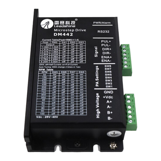
(unit: mm [inch]) The DM442 has two connectors, connector P1 for control signals connections, and connector P2 for power and motor connections. The following tables are brief descriptions of the two connectors. More detailed descriptions of the pins and related issues are presented in section 4, 5, 9. -
Page 5: Selecting Active Pulse Edge And Control Signal Mode
4 lead motors are the least flexible but easiest to wire. Speed and torque will depend on winding output). The DM442 has 3 optically isolated logic inputs which are located on connector P1 to accept inductance. In setting the drive output current, multiply the specified phase current by 1.4 to determine the peak output current. -
Page 6: Full Coil Configurations
6. Power Supply Selection The DM442 can match medium and small size stepping motors (from NEMA frame size 14 to 34) made by Leadshine or other motor manufactures around the world. To achieve good driving Figure 6: 6-lead motor full coil (higher torque) connections performances, it is important to select supply voltage and output current properly. -
Page 7: Multiple Drives
Instead, please connect them to power supply separately. 1600 Selecting Supply Voltage 3200 The power MOSFETS inside the DM442 can actually operate within +20 ~ +40VDC, including 6400 power input fluctuation and back EMF voltage generated by motor coils during motor shaft 12800 deceleration. -
Page 8: Dynamic Current Setting
DM442 Digital Stepping Drive Manual V1.0 DM442 Digital Stepping Drive Manual V1.0 high current flowing through motor coils (even when motor is at standstill). Pulling or plugging Dynamic current setting connector P2 with power on will cause extremely high back-EMF voltage surge, which may damage the drive. -
Page 9: Protection Functions
11. Protection Functions Phase error protection To improve reliability, the drive incorporates some built-in protection functions. The DM442 uses 12. Frequently Asked Questions one RED LED to indicate what protection has been activated. The periodic time of RED is 5 s (seconds), and how many times the RED turns on indicates what protection has been activated. -
Page 10: Problem Symptoms And Possible Causes
This section will provide an overview of connection and basic setup instructions for Leadshine’s Microstep resolution setting is wrong digital stepping drive DM442 using the ProTuner software. These instructions will walk you through Motor is not rotating DIP switch current setting is wrong the following steps necessary to start up your drive and motor. - Page 11 DM442 Digital Stepping Drive Manual V1.0 DM442 Digital Stepping Drive Manual V1.0 Figure 14: Installation folder settings Figure 12: License agreement Choose “I agree to the terms of this license agreement” and click Next to continue installation. The user can enter user’s information in the following window. See Figure 13. After entering the user’s information, click Next to select installation folder, where you would like to install the ProTuner.
-
Page 12: Connections And Testing
Figure 19: RS232 interface connection Testing the Stepping System Turn on the power supply, the green (Power) LED will light. The DM442 has default parameters stored in the drive. If the system has no hardware and wirings problem, the motor should be locked and the drive should be ready. -
Page 13: Software Introduction
DM442 Digital Stepping Drive Manual V1.0 DM442 Digital Stepping Drive Manual V1.0 and try again. Open the tuning software ProTuner and check drive status by clicking Err_check. If Option it’s Phase Error, check the motor, motor wirings and try again. -
Page 14: Tuning
DM442 Digital Stepping Drive Manual V1.0 DM442 Digital Stepping Drive Manual V1.0 configuration from a stored file. See figure 22. large current error, causing poor performances in tracking current setting command in each step like Figure 23. Too large Proportional Gain values will cause oscillations and unstable systems. - Page 15 However, if the user does not want to tune the current loop after changing a different stepping motor, then Motor self-test and parameter auto-setup technology of the DM442 can replace manual tuning the drive with ProTuner. Just changes SW4 two times in 1 second (without ProTuner), or click Auto...
-
Page 16: Anti-Resonance Introduction
The user can enter a value directly in the text box or move the slider bar back and forth to get an optimum value. Pulse Filter Enable: Click the check box will turn on the internal pulse smoother or filter of DM442. ResonanceArea: Parameters for 2 resonance area. -
Page 17: Procedure For Achieving Optimum Performance
DM442 Digital Stepping Drive Manual V1.0 DM442 Digital Stepping Drive Manual V1.0 installed on a machine. It is recommended that set low speed and small distance if you are not sure whether the direction and distance is correct or not. -
Page 18: About
DM442 Digital Stepping Drive Manual V1.0 OverCurrent: Over-current Protection. Protection will be activated when continuous current exceeds 16A. OverVoltage: Over-voltage Protection. When power supply voltage exceeds 42±1 VDC, protection will be activated. PhaseErr: Phase Error Protection. Motor power lines wrong & not connected will activate this protection.
Need help?
Do you have a question about the DM442 and is the answer not in the manual?
Questions and answers