
Summary of Contents for Techfluid SC250H
- Page 1 Instructions manual Series SC250 Variable area flowmeter The art of measuring R-MI-SC250 Rev.: 8 English version...
- Page 2 PREFACE Thank you for choosing a product from Tecfluid S.A. This instruction manual allows installation, configuration, programming and maintenance. It is recommended to read it before using the equipment. WARNINGS This document shall not be copied or disclosed in whole or in any part by any means, without the written permission of Tecfluid S.A.
-
Page 3: Table Of Contents
TABLE OF CONTENTS SERIES SC250 INTRODUCTION ................WORKING PRINCIPLE ..............RECEPTION .................. INSTALLATION ................Valves ................Filters ................. Straight pipe sections ............OPERATION ................. Gas flow measurement ............Gas damping mechanism ............ Liquid flow measurement ............ LIMIT SWITCH AMD INTRODUCTION ................OPERATION ................. - Page 4 TH7 TRANSMITTERS INTRODUCTION ................MODELS ..................14.1 TH7 ................... 14.2 TH7H ................. 14.3 TH7T and TH7TH ............... MOUNTING THE TRANSMITTER IN AN EXISTING EQUIPMENT ..15.1 Kit contents ................ 15.2 Preparing the kit ..............15.3 Assembling the TH7 or TH7H kit .......... 15.4 Assembling the TH7T or TH7TH kit ........
- Page 5 24.5 TH7 transmitters ..............24.7 Maintenance ..............24.6 Marking ................FLOW RANGES ................ 25.1 SC250 ................25.2 SC250H, SC250V .............. 25.3 SM250/INOX (EN 1.4404 – AISI 316L) ........51 DIMENSIONS ................DECLARATIONS OF CONFORMITY ACCORDING TO ATEX .....
-
Page 6: Series Sc250
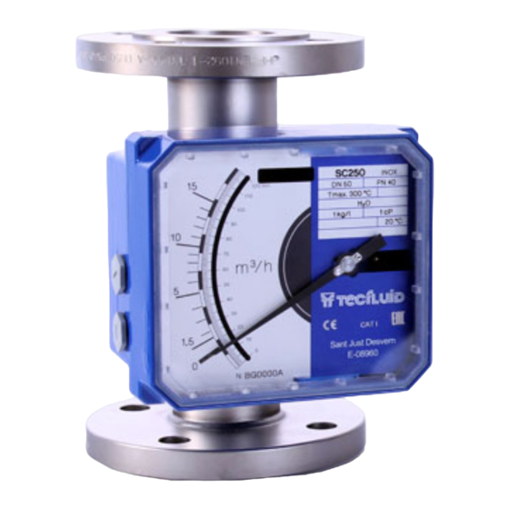
SERIES SC250 INTRODUCTION The series SC250 are flowmeters for liquids, gases and steam. They are very robust instruments prepared to work in extreme conditions. They have local flow rate indication by means of magnetic coupling, with scales calibrated in l/h, m /h, kg/h, t/h, %, etc. - Page 7 The equilibrium point is determined by considering the fluid force and the float weight. For flowmeters SC250H and SC250V, the force of the fluid moves the float and compresses a spring. This allows that the float can return to its initial position regardless of its position inside the tube when there is no flow.
-
Page 8: Reception
flow direction upwards. The flowmeter SC250V must be installed vertically (flow direction upwards or downwards). The flowmeter SC250H must be installed in horizontal position (flow direction from left to right or from right to left). The instrument must be installed so that the flow direction indicated on the dataplate of the instrument matches the flow direction of the fluid. -
Page 9: Valves
It is important that the position is completely horizontal or vertical (depending on the model of the instrument), given that deviations of about 5º can produce errors of about 8-10% of the readings. Valves If the fluid to be measured is a liquid, it is recommended to install a regulating valve before the flowmeter (see point 5.3). -
Page 10: Operation
OPERATION Once the meter is installed, the regulating valve should be opened slowly. The fluid flow will move the float which, by means of magnetic coupling, moves the indicating needle. Any variations of working conditions with respect to those when calibrated can induce reading errors. -
Page 11: Gas Damping Mechanism
If the regulation is done using the shut off valve, in open circuits or at low gas flow in the meter, the gas will expand which will sharply diminish its density, providing very serious reading errors. If the flow is regulated by the shut off valve, the float usually experiences an oscillating movement which produces a shut off action until sufficient pressure is gained to overcome its weight. -
Page 12: Liquid Flow Measurement
When measuring low pressure gas flow with AISI 316L floats, oscillation of the float often occurs, which makes it very difficult to read the flow rates. In these cases it is recommended to install a damper in the instrument. The damper consists of a piston mounted inside a cylinder, closed at its lower end. The compression forces of the gas absorb the floats oscillations, maintaining it stable in the reading point. -
Page 13: Limit Switch Amd
LIMIT SWITCH AMD INTRODUCTION The AMD limit switch can be used to generate an alarm or an operation when the flow rate that the instrument is measuring reaches a preset value on the scale plate. The AMD limit switch consists of a NAMUR slot type inductive sensor, that is actuated by a vane. -
Page 14: Mounting The Limit Switch In An Existing Equipment
MOUNTING THE LIMIT SWITCH IN AN EXISTING EQUIPMENT When the AMD limit switch is to be fitted to an existing device, please follow these steps. Kit contents The kit contains the following elements: AMD kit Quantity Material Position AMD limit switch circuit Self tapping screw DIN7982 B-2,2 x 9,5 Nº2 A2 Screw DIN7985 M3 x 6 A2 External tooth lock M3 A4... -
Page 15: Assembling The Amd Kit
Assembling the AMD kit Slide the circuit into the slot until it stops, and then screw it as shown in the figure. Slot Screw (2) Screw (2) Screw the earth cable terminal with the screw (3) and tooth lock (4). Screw (3) + tooth lock (4) Switching point adjustment... -
Page 16: Electrical Connection
To move the limit switch needle, the circular fixing nuts have to be slightly loosen by turning them to the left, without removing the scale plate (see the figure on the next page). After that, place the switching point indicator in the required scale value, and fix it again with the screw. -
Page 17: Limit Switch Amm
The numbering of the terminals is given on the printed circuit board. LIMIT SWITCH AMM INTRODUCTION The AMM limit switch can be used to generate an alarm or an operation when the flow rate or the instrument is measuring reaches a preset value on the scale plate. It consists of a micro-switch driven by a cam mounted on the indicating needle. -
Page 18: Assembling The Amm Kit
Slide the scale plate in the direction indicated in the figure, until it is released from the slot. Ensure that the O-rings (5) are placed in the thread of the gland (6). If not, they should be placed. Remove the plugs from the indicator box with a flat screwdriver and replace them by the two cable glands. -
Page 19: Switching Point Adjustment
The shaft should be held directly. For the models SC250, SC250V/BD, SC250H/DES and SM250, if the cam is turned in the “A” direction, the acting point will move away from the zero point of the scale. If the cam is turned in the “B”... -
Page 20: Mounting
11.6 Mounting Slide the scale plate into the slot until it stops as shown in the figure. Mount the cover with the four screws "Allen" M5 and the plastic washers. ELECTRICAL CONNECTION In order to make the electrical connection of the instrument, the limit switch has a screw terminal strip. -
Page 21: Th7 Transmitters
TH7 TRANSMITTERS INTRODUCTION TH7 transmitters are microprocessed electronic position transducers. The instrument uses the Hall effect to capture the field of a magnet. The resulting signal, after the micro-controller processing, is converted into a current signal of 4-20 mA in a 2-wire loop. This signal is proportional to the flow rate. -
Page 22: Preparing The Kit
In the kits, the O-rings (3) and the blanking plugs (5) are not provided as loose parts. They are incorporated in the cable glands (4). 15.2 Preparing the kit Remove the cover, unscrewing the four screws "Allen" M5 and plastic washers, in the back side of the indicator housing, using a 4 mm Allen key. -
Page 23: Assembling The Th7T Or Th7Th Kit
15.4 Assembling the TH7T or TH7TH kit Slide the circuit through the slot until it stops, and then screw it as shown in the figure. Totalizer (1) Slot Screw (2) Screw (2) The flat ribbon connecting the transmitter to the totalizer should be connected as in the figure below. -
Page 24: Mounting
15.6 Mounting Slide the scale plate into the slot until it stops as shown in the figure. Mount the cover with the four screws "Allen" M5 and the plastic washers. ELECTRICAL CONNECTION For the electrical connection, the transmitter has a screw terminal strip. For the electrical installation it is recommended to use multiple conductor cables with individual cable sections in the order of 0.25 to 0.5 mm in order to make it easier to... -
Page 25: Power Supply And Analog Output
Before connecting the power supply, you must be sure that the supply voltage is the correct one for the installation. The power supply voltage is indicated on the label of the transmitter. 16.1 Power supply and analog output The connection is made in the terminal block. The positive terminal of the power supply is connected to the position + and the positive terminal of the load in the position -. -
Page 26: Reset Input
Example of the connection of the pulse output to a PLC 16.3 Reset input The terminals marked as RESET are a reset input for the totalizer. It can be connected to a normally open potential free contact. It is important that the contact works well with low level voltages, to avoid noise effects. -
Page 27: Hart Transmitters
HART TRANSMITTERS The TH7H and TH7TH transmitters have a modem for HART communication. TH7H transmitters are fully compatible with the HART Server software from HART Communication Foundation. Tecfluid S.A. do not guarantee that the TH7H transmitter is compatible with the different servers on the market. -
Page 28: Additional Functions With Hart Communication
18.1 Additional functions with HART communication By means of the implemented commands, the user can obtain the following information: Flow rate value in the scale units Totalizer value (even if the equipment does not have a display). Reset or writing of a totalizer value. -
Page 29: 19 "Write Protect
“WRITE PROTECT” The instrument has a jumper that can be used to avoid changes in the configuration. When the jumper is connected the instrument can be configured via HART. When the jumper is removed, “Write Protect” is activated for HART, thus avoiding any changes in the configuration. -
Page 30: Port Connection
Connect the USB cable at one end to the transmitter and at the other to the computer where the software is installed. Power on the electronic converter. Execute the program WinsmeterTH7 following the sequence Start – Programs – Tecfluid S.A. - WinsmeterTH7. -
Page 31: Access To Calibration And Programming
Once the port is open, the button "Open" in the "Calibration" and “Programming” sections activates. 20.3 Access to Calibration and Programming In order to change data in the tab "Calibration", you must enter a password. The default password is calib, and it can be changed using the boxes on the right of the "Calibration"... - Page 32 Once the password is written, press "Enter" or "Open", and the Calibration or Programming tab will open. At the bottom of each section the text "Calibration tab open" or "Programming tab open" will be displayed To enter the Installation window, just click the corresponding tab. In the calibration window a complete re-calibration of the transmitter according to the scale plate can be done.
- Page 33 Likewise, to enter into the programming window, just click the corresponding tab. Changing the parameters of this screen, (see previous page) you can program the different functions of the equipment. In the box Totalizer units power can be selected. The power allows to multiply or divide by a factor multiple of 10 the totalizer speed as well as the pulse output.
-
Page 34: Visualization
To program this data to the transmitter, press the “Send” button. The programming data will be stored in the memory of the transmitter. Regardless of the programming process, in the box Totalizer value the value of the totalizer can be changed. 20.4 Visualization When the communication with the computer port is established (see section 20.2), the tab... - Page 35 To update the equipment, go to menu “Firmware” - “Update”, and a screen with the button “File” will appear. Pressing this button system can be accessed. The downloaded file has to be searched there. Once the file is selected, press the “Program” button. A message “Programming device” will appear.
-
Page 36: Maintenance
MAINTENANCE 21.1 Series SC250 To perform the maintenance of the meter, it is necessary to remove some parts of the flowmeter. Check below drawings for reference. In flowmeters up to DN80 remove the circlip (6) which locks the top float stop (7). Then remove the float stop (7). -
Page 37: Float For Sc250 With Hygienic Design
21.2 Float for SC250 with hygienic design Two special tools are necessary to disassemble the float (2) from the flowmeter. They can be supplied on demand by Tecfluid S.A. These tools fit into the side guides of the float (2) and of the float end (8). Once the tools have been fitted into their respective guides, turn the float end (8) as if it was a nut. -
Page 38: Potential Problems With The Metering Tube
21.3 Potential problems with the metering tube 21.3.1 Jammed float In flowmeters up to DN80 a possible cause is that the float upper guide (4) or the lower one (1) are bent due to a water hammer. To solve this, remove the circlip (6) which locks the top float stop (7). -
Page 39: Potential Problems With The Indicator Housing
21.4 Potential problems with the indicator housing 21.4.1 The indicator pointer rubs on the reading scale To remove the cover, remove the four screws "Allen" M5 and plastic washers, in the back side of the indicator housing, using a 4 mm Allen key. Rubbing normally happens if the meter has been hit or dropped. -
Page 40: Amd Limit Switch Maintenance
21.5 AMD limit switch maintenance 21.5.1 Electrical verification Check that the voltage at the terminals + and - is over 7.5 V when the vane is in the slot. Connect a multimeter with the scale in DC mA, in series with the terminal +. Verify that the current is less than 1 mA when the vane is in the slot, and more than 3 mA when the vane is out of the slot. -
Page 41: Technical Characteristics
TECHNICAL CHARACTERISTICS 22.1 Series SC250 Accuracy SC250, SC250H, SC250V According to VDI/VDE 3513 sheet 2 (qG=50%): 2.5% / 1.6% on request SM250 According to VDI/VDE 3513 sheet 2 (qG=50%): 1.6% Scales Direct in engineering units or in % Mounting length 250 mm, except DN150/6"... -
Page 42: Amd Limit Switch
22.2 AMD limit switch Nominal voltage Working voltage 5 ... 25 V Power supply internal resistance 1 kΩ Current with the vane into the slot < 1 mA Current with the vane out of the slot ≥ 3 mA Standard: DIN EN 60947-5-6 (NAMUR) Ambient temperature -25ºC ... -
Page 43: Th7 Transmitter
22.4 TH7 transmitter 22.4.1 Power supply 2 wire Minimum voltage (TH7 and TH7T): 0.02 Z + 12 (Volt) (Z is the load in the current loop in Ohm) The minimum value is 12 VDC for Z=0 Ohm Minimum voltage (TH7H and TH7TH): 0.02 (Z+Rext) + 14 (Volt) (Z is the load in the current loop in Ohm) The minimum value is 18 VDC for Z=0 Ohm and... -
Page 44: Safety Instructions
SAFETY INSTRUCTIONS The series SC250 flowmeters are in conformity with all essential requirements of all EC directives applicable to them: 2014/68/EU Pressure equipment directive (PED) Limit switches and transmitters: 2014/30/EU Electromagnetic compatibility directive (EMC) 2012/19/EU Waste electric and electronic equipment (WEEE). Limit switch AMM: 2014/35/EU Low voltage directive (LV) -
Page 45: Certificate Of Conformity Tr Cu (Eac Marking)
23.3 Certificate of conformity TR CU (EAC marking) Tecfluid S.A. have subjected the series SC250 of flowmeters to a certification procedure according to the technical regulations of the Customs Union of the Eurasian Economic Union (EEU). This Certificate is an official document confirming the quality of production with the standards on the territory of the Customs Union, particularly regarding safety requirements and electromagnetic compatibility. -
Page 46: Connecting Conductive Parts To Earth
24.3 Connecting conductive parts to earth When the instrument is not grounded securely through the connection process, it should be grounded through the housing screw, as shown in the figure. Earth 24.4 AMD limit switch When the equipment includes an AMD limit switch, it is certified as intrinsic safety with the following parameters: Marking Ex ia IIC T4... -
Page 47: Maintenance
The technical characteristics that differ from TH7 transmitters are the following: Maximum voltage: 30 VDC Maximum load in the 4-20 loop: 900 Ω (at 30 VDC supply voltage) Pulse output: Not available in this version. The rest of characteristics are the same as TH7 transmitter (see section 22.4). The specific intrinsic safety parameters are the following: Marking Ex ia IIC T4... -
Page 48: Flow Ranges
FLOW RANGES 25.1 SC250 Flow scales Size EN 1.4404 (AISI 316L) float (7.95 g/cm³) Float N. /h air (NPS) l/h water ΔP (mbar) 1.013 bar abs 20ºC 15025 2.5-25 0.06-0.7 15040 4-40 0.11-1.2 15060 6-60 0.2-1.8 (½”) 15100 10-100 0.3-3 15160 16-160 0.5-5... - Page 49 Flow scales Size PVC float Float N. ΔP Nm³/h air ΔP (NPS) l/h water mbar 1.013 bar abs 20ºC mbar 15025 2.5-25 0.1-1 15040 6-60 0.2-2 15060 10-100 0.4-4 (½”) 15100 16-160 0.6-6 15160 25-250 1-10 15250 40-400 1.6-16 15400 60-600 2-20 (¾”)
-
Page 50: Sc250H, Sc250V
25.2 SC250H, SC250V Flow scales Size Δp l/h water mbar (NPS) Spring N.1 Spring N.2 Spring N.3 10-100 16-160 25-250 25-250 40-400 60-600 200 / 350 100-1000 (¾”) 150-1500 250-2500 350 / 600 60-600 100-1000 160-1600 250-2500 400-4000 (1”) 600-6000... -
Page 51: Sm250/Inox (En 1.4404 - Aisi 316L)
25.3 SM250/INOX (EN 1.4404 – AISI 316L) Flow scales Δp Size Flotador EN 1.4404 (7,95 g/cm³) mbar l/h water (NPS) Type T Type V Type T Type V 6-60 12-120 (½”) 16-160 25-250 30-300 25-250 30-300 40-400 50-500 (¾”) 60-630 80-800 80-800 100-1000... -
Page 52: Dimensions
DIMENSIONS EN 1092-1 flanges C max Ø D Ø k Ø g Ø l x n SC250 SM250 SC250 SM250 14 x 4 14 x 4 18 x 4 18 x 4 18 x 8 18 x 8 18 x 8 18 x 8 22 x 8 (dimensions in mm) - Page 53 ASME B16.5 flanges C max Class Ø D Ø k Ø g Ø l x n SC250 SM250 SC250 SM250 ½" 88.9 60.3 34.9 15.90 x 4 11.1 ¾" 98.4 69.8 42.9 15.90 x 4 12.7 1" 107.9 79.4 50.8 15.90 x 4 14.3 1 ¼"...
- Page 54 Sanitary conection DIN 11851 (EN 1.4404) NW - DN Rd 34 Rd 52 Rd 65 Rd 78 Rd 95 Rd 110 Rd 130 Ø C x 1/8" x 1/6" x 1/6" x 1/6" x 1/6" x 1/4" x 1/4" Ø C 24.8 35.6 45.8...
- Page 55 Sanitary connection SMS 1145 (EN 1.4404) NW - DN Ø C Ø C 22.5 35.5 48.5 60.5 Ø d 63.5 DIN EQ. (dimensions in mm)
- Page 56 Sanitary connecton CLAMP ISO 2852 (EN 1.4404) Ø C 50.5 50.5 77.5 Ø C 24.8 35.6 45.8 58.3 82.8 Ø d 21.3 63.5 88.9 DIN EQ. 15(PC)* (dimensions in mm)
- Page 57 Threaded connection BSP / NPT (EN 1.4404) ½” ¾” 1” 1 ½” 2” 2 ½” 3” 4” DIN EQ. 15(PC)* (dimensions in mm)
-
Page 58: Declarations Of Conformity According To Atex
DECLARATIONS OF CONFORMITY ACCORDING TO ATEX... - Page 61 WARRANTY Tecfluid S.A. guarantee all the products for a period of 24 months from their sale, against all faulty materials, manufacturing or performance. This warranty does not cover failures which might be imputed to misuse, use in an application different to that specified in the order, the result of service or modification carried out by personnel not authorized by Tecfluid S.A., wrong handling or accident.
Need help?
Do you have a question about the SC250H and is the answer not in the manual?
Questions and answers